HACH SC4500, SC4200c Manual
- Basic user manual (564 pages) ,
- User instructions (292 pages) ,
- User manual (64 pages)
Advertisement
Specifications
Specifications are subject to change without notice.
| Specification | Details |
| Current | 23 mA maximum |
| Loop resistance | 12–18 VDC power supply: 0–250 Ω; 18–24 VDC power supply: 250–500 Ω |
| Wiring | Wire gauge: 0.08 to 1.5 mm2 (28 to 16 AWG) with an insulation rating of 300 VAC or higher1 |
| Operating temperature | –20 to 60°C (–4 to 140°F); 95% relative humidity, non-condensing |
| Storage temperature | –20 to 70°C (–4 to 158°F); 95% relative humidity, non-condensing |
| Certification | Listed for use with the SC4200c/SC4500 controller in Class 1, Division 2, Group A, B, C and D, Zone 2, Group IIC hazardous locations to FM and CSA safety standards by ETL |
General information
In no event will the manufacturer be liable for damages resulting from any improper use of product or failure to comply with the instructions in the manual. The manufacturer reserves the right to make changes in this manual and the products it describes at any time, without notice or obligation. Revised editions are found on the manufacturer's website.
Safety information
The manufacturer is not responsible for any damages due to misapplication or misuse of this product including, without limitation, direct, incidental and consequential damages, and disclaims such damages to the full extent permitted under applicable law. The user is solely responsible to identify critical application risks and install appropriate mechanisms to protect processes during a possible equipment malfunction.
Please read this entire manual before unpacking, setting up or operating this equipment. Pay attention to all danger and caution statements. Failure to do so could result in serious injury to the operator or damage to the equipment.
If the equipment is used in a manner that is not specified by the manufacturer, the protection provided by the equipment may be impaired. Do not use or install this equipment in any manner other than that specified in this manual.
Use of hazard information

Indicates a potentially or imminently hazardous situation which, if not avoided, will result in death or serious injury.

Indicates a potentially or imminently hazardous situation which, if not avoided, could result in death or serious injury.

Indicates a potentially hazardous situation that may result in minor or moderate injury.
1 Do not use wire gauge other than 0.08 to 1.5 mm2 (28 to 16 AWG), unless wires can be isolated from mains power and relay circuits.
Precautionary labels
NOTICE
Indicates a situation which, if not avoided, may cause damage to the instrument. Information that requires special emphasis
Read all labels and tags attached to the instrument. Personal injury or damage to the instrument could occur if not observed. A symbol on the instrument is referenced in the manual with a precautionary statement.
 | This symbol, if noted on the instrument, references the instruction manual for operation and/or safety information. |
 | This symbol indicates that a risk of electrical shock and/or electrocution exists. |
 | This symbol indicates the presence of devices sensitive to Electro-static Discharge (ESD) and indicates that care must be taken to prevent damage with the equipment. |
Class 1 Division 2 label
 | This label indicates that the module is approved for use in a Class I Div 2 A-D, T4/ Class I Zone 2 IIC, T4 environment when used with a Class I Div 2 approved SC4200c and SC4500 controllers and sensors: LDO and TSS-Ex 1. |
Precautions for hazardous location installation
Explosion hazard. Only qualified personnel should conduct the installation tasks described in this section of the manual. This equipment is suitable for use in Class 1, Division 2, Groups A, B, C & D Hazardous Locations with specified sensors and options appropriately certified and rated for Class I, Division 2, Group A, B, C & D, Zone 2, Group IIC Hazardous Locations

Explosion hazard. Do not remove or replace modules while power is supplied to the controller unless there are no ignitable gases in the area.
Explosion hazard. Do not connect or disconnect electrical components or circuits to the equipment unless power has been removed or the area is known to be non-hazardous
Explosion hazard. Connect only peripheral components that are clearly marked as certified for Class 1, Division 2 Hazardous Locations
Explosion hazard. Connect only peripheral components that are clearly marked as certified for Class 1, Division 2 Hazardous Locations.
Never connect any sensor or digital or analog module to an SC Controller that is not clearly marked as certified for Class 1, Division 2 Hazardous Locations.
Icons used in illustrations
 |  |  |  |  |
| Manufacturer supplied parts | User supplied parts | Look | Listen | Do one of these options |
Product overview
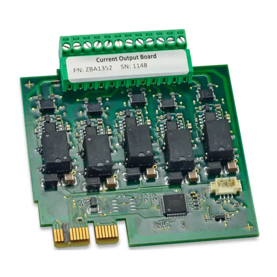
The 4–20 mA output module is an expansion card that supplies five 4–20 mA analog output connections to the SC4200c and SC4500 controllers. The module connects to the expansion modules slots inside the controller. The analog outputs are commonly used for analog signaling or to control other external devices.
Product components

Make sure that all components have been received. Refer to Figure 1. If any items are missing or damaged, contact the manufacturer or a sales representative immediately.
|
|
|
|
Installation
Multiple hazards. Only qualified personnel must conduct the tasks described in this section of the document.

Electrocution hazard. Remove power from the instrument before this procedure is started.
Electrocution hazard. High voltage wiring for the controller is conducted behind the high voltage barrier in the controller enclosure. The barrier must remain in place unless a qualified installation technician is installing wiring for power, alarms, or relays.

Electrical shock hazard. Externally connected equipment must have an applicable country safety standard assessment.
NOTICE
Make sure that the equipment is connected to the instrument in accordance with local, regional and national requirements.
Electrostatic discharge considerations
NOTICE
Potential Instrument Damage. Delicate internal electronic components can be damaged by static electricity, resulting in degraded performance or eventual failure

Refer to the steps in this procedure to prevent ESD damage to the instrument:
- Touch an earth-grounded metal surface such as the chassis of an instrument, a metal conduit orpipe to discharge static electricity from the body.
- Avoid excessive movement. Transport static-sensitive components in anti-static containers orpackages.
- Wear a wrist strap connected by a wire to earth ground.
- Work in a static-safe area with anti-static floor pads and work bench pads.
Install the unit
Install the module in the controller. Refer to the illustrated steps that follow.
Notes:
- To keep the enclosure rating, make sure that all unused electrical access holes are sealed with anaccess hole cover.
- To maintain the enclosure rating of the instrument, unused cable glands must be plugged.
- Maximum loop resistance is 500 Ω.
- The analog outputs are isolated from the other electronics, but are not isolated from each other.
- The analog outputs are self-powered. Do not connect to a load with voltage that is independentlyapplied.
- The analog outputs cannot be used to supply power to a 2-wire (loop-powered) transmitter.


NOTICE
Use cabling with a wire gauge of 0.08 to 1.5 mm2 (28 to 16 AWG)2 and an insulation rating of 300 VAC or higher. Use twisted-pair shielded wire3.
2 Do not use wire gauge other than 0.08 to 1.5 mm 2 (28 to 16 AWG), unless wires can be isolated from mains power and relay circuits.
3 Use of non-shielded cable may result in radio frequency emission or susceptibility levels higher than allowed.

Table 1 Wiring information
| Terminal | Signal | Terminal | Signal |
| 1 | Output 1+ | 7 | Output 4+ |
| 2 | Output 1– | 8 | Output 4– |
| 3 | Output 2+ | 9 | Output 5+ |
| 4 | Output 2– | 10 | Output 5– |
| 5 | Output 3+ | 11 | Shield |
| 6 | Output 3– | 12 | Shield |

Configuration
Refer to the controller documentation for instructions. Refer to the expanded user manual on the manufacturer's website for more information.
Documents / ResourcesDownload manual
Here you can download full pdf version of manual, it may contain additional safety instructions, warranty information, FCC rules, etc.
Advertisement


Need help?
Do you have a question about the SC4500 and is the answer not in the manual?
Questions and answers