Hach SC4500 User Manual
Hide thumbs
Also See for SC4500:
- User manual ,
- Basic user manual (564 pages) ,
- User instructions (292 pages)
Table of Contents
Advertisement
Advertisement
Table of Contents

Related Manuals for Hach SC4500


Summary of Contents for Hach SC4500
- Page 1 DOC343.52.90690 SC4500 08/2022, Edition 3 User Manual...
-
Page 3: Table Of Contents
6.2.1 LAN connection ..................25 6.2.2 WiFi network connection ................26 6.2.3 Cellular network connection ..............27 6.2.3.1 Configuration with Hach Cellular (Telenor) SIM ......27 6.2.3.2 Configuration with customer supplied SIM ........27 6.3 Configure the sensors or analog inputs .............. 27 6.4 Connect a USB flash drive (optional) .............. - Page 4 6.5.5 Configure the Profibus DP ................ 40 6.5.6 Configure the EtherNet/IP ............... 41 6.5.7 Configure the PROFINET ................ 41 6.6 Hach Controller Network Bus configuration ............42 6.7 Prognosys diagnostic system ................42 6.8 Claros ........................ 42 6.9 Enter license key ....................43 6.10 Show the instrument information ..............
-
Page 5: Section 1 Specifications
Section 1 Specifications Specifications are subject to change without notice. Specification Details Dimensions (W x H x D) ½ DIN-144 x 144 x 192 mm (5.7 x 5.7 x 7.6 in.) Enclosure UL50E type 4X, IEC/EN 60529–IP 66, NEMA 250 type 4X Metal enclosure with a corrosion-resistant finish Weight 1.7 kg (3.7 lb) (Controller weight without optional expansion modules) -
Page 6: Section 2 General Information
Specification Details Network connection LAN version (optional): Two Ethernet connectors (10/100 Mbps), M12 female D- coding connector; Cellular version and WiFi version (optional) USB port Used for data download and software upload. The controller records approximately 20,000 data points for each connected sensor. Compliance information CE. -
Page 7: Compliance And Certification
This is the safety alert symbol. Obey all safety messages that follow this symbol to avoid potential injury. If on the instrument, refer to the instruction manual for operation or safety information. This symbol indicates that a risk of electrical shock and/or electrocution exists. This symbol indicates the presence of devices sensitive to Electro-static Discharge (ESD) and indicates that care must be taken to prevent damage with the equipment. -
Page 8: Product Overview
The controller is supplied with a protection foil installed on the display. Make sure to remove the protection foil before the controller is used. The SC4500 is a 2-channel controller for digital analytical devices (e.g., sensors and analyzers). Refer to... -
Page 9: Optional Expansion Modules
Figure 1 Product overview 1 Label for module installation 7 USB cover 2 USB connection for external USB box (WiFi or 8 Electrical connections and fittings cellular connection) 3 Expansion module (Slot 0) 9 Protective vent 4 Additional expansion module slots 10 Cover for module installation (Slots 1, 2, 3 and 4) 5 Touchpad display... -
Page 10: Product Components
Figure 2. If any items are missing or damaged, contact the manufacturer or a sales representative immediately. Figure 2 Product components 1 SC4500 controller 7 Mounting foot (mounting bracket inserts) (2x) 2 Mounting hardware 8 Flat washer, ¼-inch ID (4x) 3 Sealing gasket for panel mount, Neoprene 9 Lock washer, ¼-inch ID (4x) -
Page 11: Installation Guidelines
Administrator rights are not necessary. The email address "No-reply@hach.com" sends the setup email and "donotreply@hach.com" sends the system notifications that are necessary for the installation. Add the two email addresses to the safe senders list to make sure to receive mails from these senders. -
Page 12: Attach The Instrument To A Pole
Figure 3 Wall mounting 3.2.2 Attach the instrument to a pole Attach the controller upright to a pole or pipe (horizontal or vertical). Make sure that the pipe diameter is 19 to 65 mm (0.75 to 2.5 in.) Refer to the illustrated steps in Figure 4 Product components on page 8 for the necessary mounting hardware. -
Page 13: Install The Instrument In A Panel
Figure 4 Pole mounting 3.2.3 Install the instrument in a panel A rectangular hole is necessary for panel installation. Use the supplied sealing gasket for panel mount as a template to cut the hole in the panel. Make sure to use the template in the up position to install the controller vertical. -
Page 14: Electrical Installation
Figure 5 Panel mounting dimensions 3.3 Electrical installation 3.3.1 Electrical connectors and fittings Figure 6 shows the electrical connectors and fittings on the instrument. To keep the environmental rating of the enclosure, make sure that there is a plug in the strain relief fittings that are not used and a connector cap on the unused connectors. - Page 15 Figure 6 Electrical connectors and fittings 1 Ethernet connector (optional) for LAN port 1 or 5 Strain relief fitting for USB box and expansion EtherNet/IP or PROFINET connector modules: Analog inputs/outputs, Profibus DP 2 Ethernet connector (optional) for LAN port 2 or 6 Power cord (or conduit hub) EtherNet/IP or PROFINET connector 3 Digital SC connector: Channel 1.
-
Page 16: Electrostatic Discharge (Esd) Considerations
Table 1 Options for each connector and fitting (continued) Device Option High voltage relay Power supply 3.3.2 Electrostatic discharge (ESD) considerations N O T I C E Potential Instrument Damage. Delicate internal electronic components can be damaged by static electricity, resulting in degraded performance or eventual failure. Refer to the steps in this procedure to prevent ESD damage to the instrument: •... -
Page 17: Remove The High-Voltage Barrier
Figure 7 Open the controller 3.3.3.2 Remove the high-voltage barrier High-voltage wiring for the controller is located behind a high-voltage barrier in the controller enclosure. Do not remove the barrier while power is supplied to the controller. Make sure that the barrier is installed before power is supplied to the controller. - Page 18 D A N G E R Electrical shock and fire hazards. Make sure to identify the local disconnect clearly for the conduit installation. W A R N I N G Potential Electrocution Hazard. If this equipment is used outdoors or in potentially wet locations, a Ground Fault Interrupt device must be used for connecting the equipment to its mains power source.
-
Page 19: Connect Conduit Or A Power Cord
• Not less than 0.75 mm (18 AWG) with applicable insulation colors for local code requirements. Flexible wires must have a crimped ferrule or pin type terminal on the end. • A power cable with a three-prong plug (with ground connection) that is applicable to the supply connection •... -
Page 20: Connect The High-Voltage Relays
Table 2 Wiring information—AC power Terminal Description Color—North America Color—EU Hot (Line 1) Black Brown Neutral (N) White Blue Protective earth ground Green Green with yellow stripe Table 3 Wiring information—DC power Terminal Description Color—North America Color—EU +24 VDC 24 VDC return Black Black Protective earth ground... - Page 21 Connect each relay to a control device or an alarm device as necessary. Refer to Figure 10 Table 4 to connect the relays. Refer to Configure the high voltage relays on page 31 to configure the trigger condition for each relay. Refer to Specifications on page 3 for the relay specifications.
-
Page 22: Install An Expansion Module
Table 4 Wiring information—relays (continued) Terminal Description Terminal Description Relay 2, NO Relay 1, NO NC = normally closed; NO = normally open 3.3.5 Install an expansion module W A R N I N G Explosion hazard. This manual is only for installation of the unit in a non-hazardous location. For installation of the unit in hazardous locations, use only the instructions and approved control drawing provided in the hazardous location installation manual. -
Page 23: Connect Measurement Devices
Figure 11 Install the high voltage barrier 3.5 Connect measurement devices Connect digital devices (e.g., sensors and analyzers) to the device connectors on the instrument. Refer to Figure 12. Keep the device connector caps for future use. Make sure that the device cables do not cause a trip hazard and do not have sharp bends. Figure 12 Connect a device English 21... -
Page 24: Section 4 User Interface And Navigation
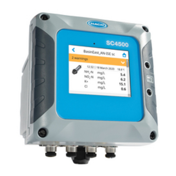
Section 4 User interface and navigation N O T I C E Do not use writing tips of pens or pencils or other sharp objects to make selections on the screen or damage to the screen will occur. Figure 13 shows an overview of the home screen. -
Page 25: Measurement Window
4.1 Measurement window The main screen shows the measurement window. The carousel icon shows at the bottom of the main screen when there are other screen views available. Each screen view has one, two or four measurement windows, based on the connected sensors and the parameters of each sensor. The controller automatically fills the measurement windows to show all of the information for the connected devices. -
Page 26: Menu Structure
5.1 Menu structure 24 English... -
Page 27: Enter Initial Settings
5.2 Enter initial settings At initial startup, follow the prompts on the display to set up the language, the date, the time and network information. Refer to Configure the controller settings on page 25 to change the settings. Section 6 Operation 6.1 Configure the controller settings Set the controller language, time, date, facility, location and display options. -
Page 28: Wifi Network Connection
3. Enter the settings. Option Description None The controller does not have Ethernet ports or the Ethernet ports are not configured. The controller is supplied with the option None by default. Note: When the controller configuration is set back to the factory settings, all of the LAN connection settings are lost and the Ethernet ports are set back to None. -
Page 29: Cellular Network Connection
USB box cellular for installation instructions. 6.2.3.1 Configuration with Hach Cellular (Telenor) SIM If the controller connects to the internet with the factory installed SIM card and the default Hach data plan (Telenor), do the steps that follow: 1. -
Page 30: Connect A Usb Flash Drive (Optional)
Note: To upgrade a one-channel controller to a two-channel controller, install a new digital SC connector. Refer to the documentation supplied with the connector upgrade kit. The connected devices show on the main screen and in the Devices menu. When the controller connects to a network or Claros, the devices of the network also show. -
Page 31: Data Download
Figure 15 USB flash drive connection 6.4.1 Data download The controller records in an internal memory the data that follows: • Approximately 20,000 data points, diagnostics data and an event log of all of the connected sensors and expansion modules •... -
Page 32: Install Sensor Firmware Updates
2. Copy the file to the root folder of the USB flash drive. Make sure that the files are in the correct folder. Installation files must be in: D [USB drive unit]:\HACH\Firmware\[sensor name with MID and IID]\installation file name with code [MID/IID], package number [P] identification file [AC/BC/DD] and version number. -
Page 33: Restore The Firmware
6. Follow the instructions on the screen to install the firmware update. 7. When the update is complete, a message shows on the display. Remove the USB flash drive. Note: If there is an error during the firmware update, a message shows on the display. Refer to Troubleshooting on page 45. - Page 34 Option Description Function Sets the function value. Setup options change based on the selected function. • Alarm—Operates the relays in response to the measured parameter. • Feeder control—Operates the relays in response to the measured parameter. • 2 point control—Operates the relays in response to the measured parameter with two setpoints.
- Page 35 Option Description Maximum timer Indicates a period of time (in seconds) for the expiration of the OnMax TIMER and the expiration OffMax TIMER. Relay set to ON, OnMax TIMER set to ON: The time left is displayed before the relay is set to OFF automatically.
- Page 36 Option Description Error list Sets the monitoring of the internal error bits of the selected source. Enabled: Monitoring is active. Disabled (default): Monitoring is not active. Process event Sets the monitoring of the internal process event bits of the selected source. Enabled: Monitoring is active.
- Page 37 Option Description Integral Sets the integration part of the PID controller. The integration part of the controller generates an output signal. The output signal increases linearly if the control deviation is constant. The integration part responds slower than the proportional part and can completely compensate disturbances. The higher the integration part, the slower it responds.
- Page 38 Timer function Option Description Outputs on hold Lets the relay put a mark on the sensor configured in the menu SENSOR at the DURATION time. Other expansion modules such as other relay cards or current output cards which access data of this sensor read this 'mark' and go into hold. To go into hold means the accessing module does not read the latest measurement from the marked sensor but works with the last measurement read before the sensor was marked.
-
Page 39: Configure The Analog Outputs
6.5.2 Configure the analog outputs Make sure that a 4-20 mA output module is installed in the controller. Refer to the documentation supplied with the module. Make sure that all of the necessary electrical connections are complete before the 4-20 mA output is configured. 1. -
Page 40: Configure The Telegram
PID control function Option Description Error mode Sets the controller to not change the analog output value (Hold) or show the transfer value on the analog output when an internal error occurs. Options: Hold or Transfer Mode Sets the output condition when the process value is out of the controlled band. Options: Direct control or Reverse Mode Automatic—The output works as a PID controller. -
Page 41: Configure The Modbus Tcp
c. Select the devices to remove and push OK. Confirm to remove the selected devices from the telegram list. Note: Use the drag and drop function to change the elements on the Telegram list. Push and hold on the element and move the device or tag to the new position. -
Page 42: Configure The Profibus Dp
Option Description Status Shows information about the data transfer. External Shows when the controller is added to the Telegram menu. For each measurement tag measurements (1 to 16) added in the Telegram menu, select a Parameter and Unit that will show on the tag for external measurements as follows: 1. -
Page 43: Configure The Ethernet/Ip
Option Description Location Sets the location name to identify the Profibus network module. Default: network module serial number Status Shows the condition of the Profibus network module. • Status—Options: Please wait—Shows until the network module finds all of the configured secondary devices or shows when the module configuration is new and looks for devices connections. -
Page 44: Hach Controller Network Bus Configuration
6.6 Hach Controller Network Bus configuration The Hach Controller Network Bus (HCNB) is a network used to share the connection to the PLC embedded by one controller and configure the system with remote sensors connected to other controllers (SC4500, SC4200c, SC1500 or RTC). The HCNB is applicable to Claros and non-Claros controllers, but all of the controllers must be connected to the HCNB. -
Page 45: Enter License Key
4. Connect to your Claros account and provision the controller. Follow the steps in the Claros interface. Note: Contact Hach to learn more about Claros or to get a Claros account. Note: Sensor measurements may go out of view until the controller is successfully provisioned to Claros. If the controller is disconnected from Claros, make sure to set the Claros button to off to show sensor measurements on the display. -
Page 46: Clean The Instrument
7.1 Clean the instrument Clean the exterior of the instrument with a moist cloth and a mild soap solution and then wipe the instrument dry as necessary. Note: The manufacturer recommends that the screen is locked during cleaning, or when a waterjet is used near the controller. -
Page 47: Section 8 Troubleshooting
Section 8 Troubleshooting Problem Possible cause Solution Controller will not Power is not supplied to Make sure that the power cable is connected to the power up, or powers up the controller. controller. intermittently. Make sure that the power connections are properly terminated in the controller. - Page 48 Problem Possible cause Solution No relay activation Incorrect relay connection Make sure that the relay connections are secure. or configuration Make sure that the relay wiring is correct. Make sure that the relay configuration is correct. The relay should energize and de-energize as selected. The controller does not Non-compatible USB Make sure that the USB flash drive is formatted with...
-
Page 49: Section 9 Replacement Parts And Accessories
Problem Possible cause Solution Time synchronization The controller cannot Make sure that there are no restrictions to external access access the NPT internet in the controller network. service to get the clock Contact your IT department and make sure that the automatically network has access to the internet NTP service. - Page 50 SC4500 Profibus DP network module LXZ524.99.00007 SC4500 PROFINET upgrade Kit LXZ525.99.C0001 SC4500 EtherNet/IP upgrade Kit LXZ525.99.C0002 SC4500 Modbus TCP upgrade Kit LXZ525.99.C0003 SC4500 connector upgrade Kit, includes cable nut and cap LXZ525.99.00001 SC4500 mA input module LXZ524.97.00042 LXZ524.98.00042 SC4500 pH/ORP module LXZ525.99.D0003 Accessories...
-
Page 51: Appendix A Telegram Tag List
Appendix A Telegram tag list Legend: • Device—Shows all of the SC devices that can be selected for the SC4500 controller as source (for mA output or High voltage relay) or as device in Telegram (for Profibus DP, Modbus TCP, PROFINET and EtherNet/IP). - Page 52 Integer — — ✓ ✓ ✓ ✓ (refer to Note 2) Heartbeat Integer — — ✓ ✓ ✓ ✓ SC4500 Measurement 1 Float ✓ ✓ ✓ ✓ ✓ ✓ (refer to Note 3) SC4500 Measurement 10 Float ✓ ✓ ✓...
- Page 53 Device Name Type mA-O HVR P-DP M-TCP PRN E/IP MAOUTPUT Current ch2 [mA] Float — ✓ ✓ ✓ ✓ ✓ MAOUTPUT Current ch3 [mA] Float — ✓ ✓ ✓ ✓ ✓ MAOUTPUT Current ch4 [mA] Float — ✓ ✓ ✓ ✓...
- Page 54 Device Name Type mA-O HVR P-DP M-TCP PRN E/IP mA input Set of eight generic tags Integer — — ✓ ✓ ✓ ✓ mA input Current [mA] Float ✓ ✓ ✓ ✓ ✓ ✓ mA input Input Float ✓ ✓ ✓...
- Page 55 Device Name Type mA-O HVR P-DP M-TCP PRN E/IP A-ISE sc Temperature [°C] Float ✓ ✓ ✓ ✓ ✓ ✓ A-ISE sc Temperature [°F] Float ✓ ✓ ✓ ✓ ✓ ✓ AN-ISE sc Measurement indicator [%] Integer — — ✓ ✓...
- Page 56 Device Name Type mA-O HVR P-DP M-TCP PRN E/IP LDO2 sc Dissolved Oxygen [mg/L] Float ✓ ✓ ✓ ✓ ✓ ✓ LDO2 sc Dissolved Oxygen [ppm] Float ✓ ✓ ✓ ✓ ✓ ✓ LDO2 sc Temperature [°C] Float ✓ ✓ ✓...
- Page 57 Device Name Type mA-O HVR P-DP M-TCP PRN E/IP PHOSPHAX sc MR Cleaning solution level [%] Float ✓ ✓ ✓ ✓ ✓ ✓ PHOSPHAX sc MR Phosphate-Phosphorus PO4-P Float ✓ ✓ ✓ ✓ ✓ ✓ ch1 [mg/L or ppm] PHOSPHAX sc MR Phosphate-Phosphorus PO4-P Float ✓...
- Page 58 Device Name Type mA-O HVR P-DP M-TCP PRN E/IP SOLITAX sc Solid [%] Float ✓ ✓ ✓ ✓ ✓ ✓ SOLITAX sc Solid [g/L] Float ✓ ✓ ✓ ✓ ✓ ✓ SOLITAX sc Solid [mg/L] Float ✓ ✓ ✓ ✓ ✓...
- Page 59 Device Name Type mA-O HVR P-DP M-TCP PRN E/IP TU5400 sc Set of eight generic tags Integer — — ✓ ✓ ✓ ✓ TU5400 sc Measurement indicator [%] Integer — — ✓ ✓ ✓ ✓ TU5400 sc Service indicator [days] Integer —...
- Page 60 Device Name Type mA-O HVR P-DP M-TCP PRN E/IP 3798-S sc V2 Resistivity [Ohm.m] Float ✓ ✓ ✓ ✓ ✓ ✓ 3798-S sc V2 Temperature [°C] Float ✓ ✓ ✓ ✓ ✓ ✓ 3798-S sc V2 Temperature [°F] Float ✓ ✓...
- Page 61 Device Name Type mA-O HVR P-DP M-TCP PRN E/IP D3422 (digital) - 3400 sc Salinity [ppt] Float ✓ ✓ ✓ ✓ ✓ ✓ D3422 (digital) - 3400 sc Temperature [°C] Float ✓ ✓ ✓ ✓ ✓ ✓ D3422 (digital) - 3400 sc Temperature [°F] Float ✓...
- Page 62 Device Name Type mA-O HVR P-DP M-TCP PRN E/IP RC and PC (analog) + Temperature [°C] Float ✓ ✓ ✓ ✓ ✓ ✓ Gateway (6120600) RC and PC (analog) + Temperature [°F] Float ✓ ✓ ✓ ✓ ✓ ✓ Gateway (6120600) RC and PC (analog) + pH [pH] Float...
- Page 64 Tel. +49 (0) 2 11 52 88-320 SWITZERLAND Fax (970) 669-2932 Fax +49 (0) 2 11 52 88-210 Tel. +41 22 594 6400 orders@hach.com info-de@hach.com Fax +41 22 594 6499 www.hach.com www.de.hach.com © Hach Company/Hach Lange GmbH, 2021–2022. All rights reserved.
Need help?
Do you have a question about the SC4500 and is the answer not in the manual?
Questions and answers
How to reset to factory settings?