Table of Contents
Advertisement
Quick Links
Advertisement
Table of Contents

Related Manuals for IBASE Technology AMS310


Summary of Contents for IBASE Technology AMS310
- Page 1 AMS310 Compact Expandable Fanless System User’s Manual Version 1.0 (March 2023)
- Page 2 No part of this publication may be reproduced, copied, stored in a retrieval system, translated into any language or transmitted in any form or by any means, electronic, mechanical, photocopying, or otherwise, without the prior written consent of IBASE Technology, Inc. (hereinafter referred to as “IBASE”).
- Page 3 CE conformity declaration may no longer apply. AMS310 has been tested and found to comply with the limits for a Class B device pursuant to Part 15 of the FCC Rules. These limits are designed to provide reasonable protection against harmful interference in a residential installation.
- Page 4 You are not suggested to disassemble, repair or make any modification to the device. Disassembly, modification, or any attempt at repair could generate hazards and cause damage to the device, even bodily injury or property damage, and will void any warranty. AMS310 User Manual...
- Page 5 Software in use (such as OS and application software, including the version numbers) 3. If repair service is required, you can download the RMA form at http://www.ibase.com.tw/english/Supports/RMAService/. Fill out the form and contact your distributor or sales representative. AMS310 User Manual...
-
Page 6: Table Of Contents
Packing List ....................3 Optional Accessories ................. 3 Specifications .................... 4 Product View – AMS310 ................6 Dimensions – AMS310 ................8 Chapter 2 Hardware Configuration ............11 Hardware Installations ................12 ... - Page 7 Boot Settings ................... 60 Save & Exit Settings ................61 Appendix ....................... 62 I/O Port Address Map ................63 Interrupt Request Lines (IRQ) ..............65 Watchdog Timer Configuration ..............66 AMS310 User Manual...
- Page 8 This page is intentionally left blank. viii AMS310 User Manual...
-
Page 9: Chapter 1 General Information
Chapter 1 General Information The information provided in this chapter includes: Features Packing List Optional Accessories Specifications Product View Dimensions... -
Page 10: Introduction
-10ºC to 60ºC. It is built with a passive finned heat sink to provide effective transfer of heat away from components. The AMS310 houses the IBASE MB310 board with Intel Q470E PCH and supports 10th Gen Intel®... -
Page 11: Packing List
Round Head Screw (for Wall Mount Kit) Disk (including drivers and this user manual) 1.4 Optional Accessories WiFi / Bluetooth antenna kit LTE / 5G antenna kit GPS antenna kit 180W power adaptor AMS310 User Manual... -
Page 12: Specifications
1x 2.5'' HDD/SSD (external-accessible) Storage 1x M.2 2280 M-Key (SATA & PCI-E) Construction Aluminum & steel Chassis Color Color Silver & Gray Mounting Desktop or wall mounting (wall mount kit included) Side mounting DIN-rail mounting (optional) AMS310 User Manual... - Page 13 Operatiing: 0.25 grms / 5~500Hz / random operation Operating: 20 g / 11 ms Shock Non-operating: 40 g / 11 ms Certification CE / LVD / FCC Class-B All specifications are subject to change without prior notice. AMS310 User Manual...
-
Page 14: Product View - Ams310
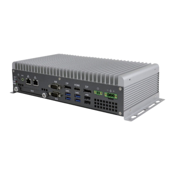
1.6 Product View – AMS310 Front View Name Name LED Indicator (LED1) HDMI Port (CN7) (from top to bottom: S1*, E1*, SSD, HDD, Power) Power Button (SW1) DP Port (CN5) Audio Jack for Line-Out (CN15) USB 3.0 Ports (CN6, CN8) 2x GbE LAN (CN14, CN13) USB 2.0 Ports (CN4) - Page 15 General Information The rear view shows six antenna connectors. AMS310 with antennas installed at the rear. AMS310 User Manual...
-
Page 16: Dimensions - Ams310
1.7 Dimensions – AMS310 Unit: mm AMS310 User Manual... - Page 17 General Information Unit: mm AMS310 User Manual...
- Page 18 MB310 Motherboard Dimensions AMS310 User Manual...
-
Page 19: Chapter 2 Hardware Configuration
Chapter 2 Hardware Configuration The information provided in this chapter includes: Essential installations before you begin Information and locations of connectors... -
Page 20: Hardware Installations
4. Gently push the module in an upright position until the ejector tabs of the memory slot close to hold the module in place when the module touches the bottom of the slot. To remove the module, press the ejector tabs outwards with your fingertips to eject the module. AMS310 User Manual... -
Page 21: Installation / Replacement
M.2 Installation / Replacement 1. After removing the bottom cover, locate the M.2 sockets. 2. There are three M.2 sockets available on AMS310 (J15: M-Key, J12: B-Key, and J3: E-Key), as shown in the picture below. Locate the desired socket to be used for installation/replacement of M.2 devices to proceed. -
Page 22: Ssd Installation
2.1.3 SSD Installation 1. To install or replace the SSD, follow the instructions below. Release 2 screws to pull out the SSD tray. Tray 4 screws Remove/replace the four screws shown to remove or install the SSD. AMS310 User Manual... -
Page 23: Wifi / 3G / 4G Antenna Installation
The AMS310 system comes with a set of wall mount kit and four round head screws that are to be used in securing the mounting brackets to the main unit, as shown in the picture below. -
Page 24: Dc-In & Power Button Connectors
2.1.6 DC-In & Power Button Connectors DC-In Power Connector (3-pin terminal block) Assigment Case Ground Power Ground Remote Control Connector (2-pin terminal block) Assigment Power BTN Ground AMS310 User Manual... -
Page 25: Jumper Setting
1 2 3 When two pins of a jumper are encased in a jumper cap, this jumper is closed, i.e. turned On. When a jumper cap is removed from two jumper pins, this jumper is open, i.e. turned Off. AMS310 User Manual... -
Page 26: Jumper & Connector Locations On Motherboard
2.3 Jumper & Connector Locations on Motherboard Motherboard: MB310 AMS310 User Manual... -
Page 27: Jumpers Quick Reference
2.4 Jumpers Quick Reference Function Jumper Clear CMOS Data Clear ME COM2 RS-232 Power Selection AT/ATX Mode Setting PCIe (x16) Bifurcation Selection JP5, JP6 2.4.1 Clear CMOS Data (JP2) Function Illustration Normal (default) Closed Clear CMOS Closed AMS310 User Manual... -
Page 28: Clear Me Data (Jp1)
2.4.2 Clear ME Data (JP1) Function Illustration Normal (default) 1-2 Closed Clear ME 2-3 Closed 2.4.3 COM2 RS-232 Power Selection (JP7) Function Pin closed Illustration Normal (default) AMS310 User Manual... -
Page 29: At/Atx Mode Setting (Jp4)
Hardware Configuration 2.4.4 AT/ATX Mode Setting (JP4) Function Illustration ATX Mode 1-2 Closed (default) AT Mode 2-3 Closed AMS310 User Manual... - Page 30 2.4.5 PCIe (x16) Bifurcation Selection (JP5 & JP6) Function Illustration JP5: Open 1 x PCIe (x16) (default) JP6: Open JP5: Open 2 x PCIe (x8) JP6: Close JP5: Close RSVD JP6: Open JP5: Close 1 x PCIe (x8) 2 x PCIe (x4) JP6: Close AMS310 User Manual...
-
Page 31: Connectors Quick Reference
Terminal Block for Remote Access COM1/COM2 Ports CN10 LAN2 (I225V 2.5G) CN13 LAN3 (I225V 2.5G) CN14 System Fan Power Connector SYS_FAN1 Audio Jack for Line Out CN15 DisplayPort CN8, CN4 HDMI Port USB 3.0 Ports CN9, CN7 USB 2.0 Ports AMS310 User Manual... -
Page 32: J2: Spi Debug Tools Pin Header
2.5.1 J2: SPI Debug tools Pin Header 2.5.2 J3: M.2 E-Key Socket Note: J3 supports USB2.0 & PCIe (for wifi module) AMS310 User Manual... -
Page 33: Sata Hdd Power Connector (J9)
Hardware Configuration 2.5.3 SATA HDD Power Connector (J9) Signal Name Signal Name Ground Ground +12V 2.5.4 Digital I/O (J7) AMS310 User Manual... -
Page 34: Spi Firmware Header (J8)
2.5.5 SPI Firmware Header (J8) 2.5.6 M.2 B-Key Socket (J12) Note: J12 supports USB2.0 & 3.0, and 4G/5G module; (Non-Sierra 5G module) AMS310 User Manual... -
Page 35: M-Key Socket (J15)
Hardware Configuration 2.5.7 M.2 M-Key Socket (J15) Note: J15 supports SATA & PCIe x4 (for storage) AMS310 User Manual... -
Page 36: Reset Switch (J17)
2.5.8 Reset Switch (J17) Signal Name Reset# Ground 2.5.9 DC-In Power Connector (J18) Note: J18 is a 3-pin terminal block. Signal Name Case Ground Ground AMS310 User Manual... -
Page 37: Led Indicators (Led1)
Hardware Configuration 2.5.10 LED indicators (LED1) Note: LED1 consists of Power, HDD, and 2x error warning. Green (Power LED) Red (HDD) Blue (GPIO) Green/Yellow (GPIO) 2.5.11 PCI-Express (x16) (PCIE1) AMS310 User Manual... -
Page 38: Pci-Express (X4) (Pcie2)
2.5.12 PCI-Express (x4) (PCIE2) Note: PCIE2 is used with IP301 and IP302. The signal shall be 1x PCI-E(x1) [36 pins] and 3x USB2.0 / 2x RS232 2.5.13 Terminal Block Connector for Remote Access (CN3) AMS310 User Manual... -
Page 39: Com1/Com2 Ports (Cn10)
COM1~2 port is jumper-less and configurable in the BIOS. Assigment Assigment DCD, Data carrier detect DSR, Data set ready RXD, Receive data RTS, Request to send TXD, Transmit data CTS, Clear to send DTR, Data terminal ready RI, Ring indicator Ground AMS310 User Manual... -
Page 40: Lan2 (I225V 2.5G) (Cn13)
2.5.15 LAN2 (I225V 2.5G) (CN13) 2.5.16 LAN3 (I225V 2.5G) (CN14) AMS310 User Manual... -
Page 41: System Fan Power Connector (Sys_Fan1)
Hardware Configuration 2.5.17 System Fan Power Connector (SYS_FAN1) Assignment Ground Rotation detection AMS310 User Manual... -
Page 42: Chapter 3 Driver Installation
Chapter 3 Driver Installation The information provided in this chapter includes: Intel ® Chipset Software Installation Utility Graphics Driver Installation HD Audio Driver Installation LAN Driver Installation Intel ® Management Engine Driver Installation... -
Page 43: Introduction
INF files for Plug & Play function for the chipset components. Follow the instructions below to complete the installation. 1. Run the drivers disk.Click Intel and then Intel(R) CometLake Chipset Drivers. 2. Click Intel(R) Chipset Software Installation Utility. AMS310 User Manual... - Page 44 Next to continue. 4. Accept the software license agreement. 5. On the Readme File Information screen, click Install. ® 6. When Intel Chipset Device Software has been completely installed, click Finish to complete the setup process. AMS310 User Manual...
-
Page 45: Graphics Driver Installation
3. When the Welcome screen appears, click Next. 4. Accept the license agreement and click Yes. 5. On the Readme File Information screen, click Next. 6. In the Setup Progress screen, click Next. 7. When Setup is Complete, click Finish to restart the computer. AMS310 User Manual... -
Page 46: Hd Audio Driver Installation
1. Run the drivers disk. Click Intel and then Intel(R) CometLake Chipset Drivers. 2. Click Realtek High Definition Audio Driver. 3. On the Welcome screen of the InstallShield Wizard, click Next. 4. When InstallShield Wizard has completed the installation, restart the computer. AMS310 User Manual... -
Page 47: Lan Driver Installation
5. Accept the License Agreement and click Next. 6. Click Next in the Setup Options screen as shown below. 7. Install Wizard is now ready to install the program, click Install. 8. When Install Wizard has completed the installation, click Finish. AMS310 User Manual... -
Page 48: Intel Management Engine Driver Installation
4. Accept the licence agreement and click Next to continue. 5. Click Next to install to the default folder, or click Change to choose another destination folder. 6. When the Intel Management Engine Components has been successfully installed, click Finish. AMS310 User Manual... -
Page 49: Chapter 4 Bios Setup
Chapter 4 BIOS Setup This chapter describes the different settings available in the AMI BIOS that comes with the board. The topics covered in this chapter are as follows: Main Settings Advanced Settings Chipset Settings Security Settings ... -
Page 50: Introduction
These defaults have been carefully chosen by both AMI and your system manufacturer to provide the absolute maximum performance and reliability. Changing the defaults could make the system unstable and crash in some cases. AMS310 User Manual... -
Page 51: Main Settings
BIOS Setup 4.3 Main Settings BIOS Setting Description Sets the date. System Date Use the <Tab> key to switch between date elements. Set the time. System Time Use the <Tab> key to switch between time elements. AMS310 User Manual... -
Page 52: Advanced Settings
Displays super IO chip parameters. Configuration F81964 Hardware Shows super IO monitor hardware status. Monitor Configures management engine technology PCH-FW Configuration parameters. USB Configuration Displays USB configuration parameters. Network Stack Enable/Disable UEFI Network Stack. Configuration NVMe Configuration Configures NVME Device AMS310 User Manual... - Page 53 When enabled, a VMM can utilize the Technology additional hardware capabilities provided by Vanderpool Technology. Active Processor Cores Number of cores to enable in each processor package. Hyper-Threading Enable or Disable Hyper-Threading Technology. Enables / Disables AES (Advanced Encryption Standard). AMS310 User Manual...
- Page 54 4.4.2 Power & Performance AMS310 User Manual...
- Page 55 PCH-FW Configuration BIOS Setting Description When disabled AMT BIOS features are no longer supported and user is no longer able to access MEBx Setup. AMT BIOS Features Note: This option does not disable manageability features in FW. AMS310 User Manual...
- Page 56 4.4.4 Trusted Computing AMS310 User Manual...
- Page 57 Enables / Disables the system ability to Enable Hibernation hibernate (OS/S4 Sleep State). This option may not be effective with some OS. Selects a ACPI sleep state for the system to ACPI Sleep State enter. Options: Suspend Disabled, S3 (Suspend to RAM) AMS310 User Manual...
- Page 58 4.4.6 F81964 Super IO Configuration AMS310 User Manual...
- Page 59 BIOS Setup AMS310 User Manual...
- Page 60 Options: Disabled (default),. 50 °C, 60 °C, 70 °C, 80 °C These fields are the parameters of the hardware monitoring function feature of the Temperatures / Voltages motherboard. The values are read-only as monitored by the system and showing the PC health status AMS310 User Manual...
- Page 61 Maximum time the device will take before it properly reports itself to the Host Controller. Device power-up delay ‘Auto’ uses default value: for a Root port it is 100 ms, for a Hub port the delay is taken from Hub descriptor. Options: Auto, Manual AMS310 User Manual...
- Page 62 4.4.9 Network Stack Configuration BIOS Setting Description Network Stack Enable/Disable UEFI Network Stack 4.4.10 NVME Configuration AMS310 User Manual...
-
Page 63: Chipset Settings
BIOS Setup 4.5 Chipset Settings BIOS Setting Description System Agent (SA) System Agent (SA) parameters Configuration VT-d Enables / Disables VT-d capability. 4.5.1 System Agent Configuration AMS310 User Manual... - Page 64 BIOS Setting Description SATA and RST SATA device options and settings Configuration PCH LAN Controller Enables / Disables onboard NIC. Enables / Disables integrated LAN to wake the Wake on LAN Enable system. 4.5.2 PCH-IO Configuration AMS310 User Manual...
-
Page 65: Security Settings
BIOS Setup 4.6 Security Settings BIOS Setting Description Administrator Password Sets an administrator password. User Password Sets a user password. Secure Boot Secure Boot configuration AMS310 User Manual... - Page 66 AMS310 User Manual...
- Page 67 BIOS Setup AMS310 User Manual...
-
Page 68: Boot Settings
Selects the keyboard NumLock state. Quiet Boot Enables / Disables Quiet Boot option. Fixed Boot Order Priorities Sets the system boot order. UEFI Hark Disk Drive BBS Specifies the Boot Device Priority sequence Priorities from available UefI Hark Disk Drives. AMS310 User Manual... -
Page 69: Save & Exit Settings
Saves the changes done so far as user defaults. Restores the user defaults to all the setup Restore User Defaults options. Attempts to launch EFI Shell application Launch EFI Shell from (Shell.efi) from one of the available filesystem filesystem device devices AMS310 User Manual... -
Page 70: Appendix
Appendix This section provides the mapping addresses of peripheral devices and the sample code of watchdog timer configuration. I/O Port Address Map Interrupt Request Lines (IRQ) Watchdog Timer Configuration... -
Page 71: I/O Port Address Map
Intel(R) SMBus - 06A3 0x000003F8-0x000003FF Communications Port (COM1) 0x000002F8-0x000002FF Communications Port (COM2) 0x000003E8-0x000003EF Communications Port (COM3) 0x000002E8-0x000002EF Communications Port (COM4) 0x00000020-0x00000021 Programmable interrupt controller 0x00000024-0x00000025 Programmable interrupt controller 0x00000028-0x00000029 Programmable interrupt controller 0x0000002C-0x0000002D Programmable interrupt controller 0x00000030-0x00000031 Programmable interrupt controller AMS310 User Manual... - Page 72 0x00000D00-0x0000FFFF PCI Express Root Complex 0x00000040-0x00000043 System timer 0x00000050-0x00000053 System timer 0x00001854-0x00001857 Motherboard resources 0x00002000-0x000020FE Motherboard resources 0x00003000-0x0000303F Intel(R) UHD Graphics 630 0x00003090-0x00003097 Standard SATA AHCI Controller 0x00003080-0x00003083 Standard SATA AHCI Controller 0x00003060-0x0000307F Standard SATA AHCI Controller AMS310 User Manual...
-
Page 73: Interrupt Request Lines (Irq)
IRQ 4294967291 Standard SATA AHCI Controller IRQ 4294967279~83 Intel(R) Ethernet Controller (3) I225-V IRQ 4294967284~88 Intel(R) Ethernet Controller (3) I225-V #2 IRQ 4294967278 Intel(R) Management Engine Interface IRQ 4294967294 Intel(R) PCI Express Root Port #12 - 06B3 AMS310 User Manual... -
Page 74: Watchdog Timer Configuration
**endptr; char SIO; printf("Fintek 81964 watch dog program\n"); SIO = Init_F81964(); if (SIO == 0) printf("Can not detect Fintek 81964, program abort.\n"); return(1); }//if (SIO == 0) if (argc != 2) AMS310 User Manual... - Page 75 //enable WDTO output bBuf = Get_F81964_Reg(0xF5); bBuf |= 0x20; Set_F81964_Reg(0xF5, bBuf); //start counting //--------------------------------------------------------------------------- void DisableWDT(void) unsigned char bBuf; Set_F81964_LD(0x07); //switch to logic device 7 bBuf = Get_F81964_Reg(0xFA); bBuf &= ~0x01; Set_F81964_Reg(0xFA, bBuf); //disable WDTO output AMS310 User Manual...
- Page 76 = Get_F81964_Reg(0x20); if (ucDid == 0x07) //Fintek 81964 { goto Init_Finish; } F81964_BASE = 0x2E; result = F81964_BASE; ucDid = Get_F81964_Reg(0x20); if (ucDid == 0x07) //Fintek 81964 { goto Init_Finish; } F81964_BASE = 0x00; result = F81964_BASE; Init_Finish: AMS310 User Manual...
- Page 77 LD); Lock_F81964(); //--------------------------------------------------------------------------- void Set_F81964_Reg( unsigned char REG, unsigned char DATA) Unlock_F81964(); outportb(F81964_INDEX_PORT, REG); outportb(F81964_DATA_PORT, DATA); Lock_F81964(); //--------------------------------------------------------------------------- unsigned char Get_F81964_Reg(unsigned char REG) unsigned char Result; Unlock_F81964(); outportb(F81964_INDEX_PORT, REG); Result = inportb(F81964_DATA_PORT); Lock_F81964(); return Result; //--------------------------------------------------------------------------- AMS310 User Manual...
- Page 78 #define F81964_DATA_PORT (F81964_BASE+1) //--------------------------------------------------------------------------- #define F81964_REG_LD 0x07 //--------------------------------------------------------------------------- #define F81964_UNLOCK 0x87 #define F81964_LOCK 0xAA //--------------------------------------------------------------------------- unsigned int Init_F81964(void); void Set_F81964_LD( unsigned char); void Set_F81964_Reg( unsigned char, unsigned char); unsigned char Get_F81964_Reg( unsigned char); //--------------------------------------------------------------------------- #endif // F81964_H AMS310 User Manual...
Need help?
Do you have a question about the AMS310 and is the answer not in the manual?
Questions and answers