
Subscribe to Our Youtube Channel
Related Manuals for IBASE Technology AMI220


Summary of Contents for IBASE Technology AMI220
- Page 1 AMI220 AMI221 AMI222 High Performance Fanless System User’s Manual Version 1.1 (Feb. 2019)
- Page 2 No part of this publication may be reproduced, copied, stored in a retrieval system, translated into any language or transmitted in any form or by any means, electronic, mechanical, photocopying, or otherwise, without the prior written consent of IBASE Technology, Inc. (hereinafter referred to as “IBASE”).
-
Page 3: Compliance
0.1% by weight (1000 ppm) except for cadmium, limited to 0.01% by weight (100 ppm). • Lead (Pb) • Mercury (Hg) • Cadmium (Cd) • Hexavalent chromium (Cr6+) • Polybrominated biphenyls (PBB) • Polybrominated diphenyl ether (PBDE) AMI220 / 221 / 222 User Manual... -
Page 4: Important Safety Information
You are not suggested to disassemble, repair or make any modification to the device. Disassembly, modification, or any attempt at repair could generate hazards and cause damage to the device, even bodily injury or property damage, and will void any warranty. AMI220 / 221 / 222 User Manual... -
Page 5: Caution
Software in use (such as OS and application software, including the version • numbers) 3. If repair service is required, you can download the RMA form at http://www.ibase.com.tw/english/Supports/RMAService/. Fill out the form and contact your distributor or sales representative. AMI220 / 221 / 222 User Manual... -
Page 6: Table Of Contents
WiFi / 3G / 4G Antenna Installation ......... 27 2.1.6 Expansion Card Installation ............ 27 2.1.7 Wall Mount Installation ............29 2.1.8 Pinout for COM Ports, DC-In & Power Button Connectors ..31 Setting the Jumpers ................33 AMI220 / 221 / 222 User Manual... - Page 7 F81846 Hardware Monitor ............63 4.4.7 CPU Configuration ..............64 4.4.8 SATA Configuration ..............65 4.4.9 CSM Configuration ..............66 4.4.10 USB Configuration ..............67 Chipset Settings ..................69 4.5.1 System Agent (SA) Configuration ........... 70 AMI220 / 221 / 222 User Manual...
- Page 8 Save & Exit Settings................75 Appendix ...................... 76 Compatible Expansion Cards for AMI221 & AMI222 ......77 I/O Port Address Map ................79 Interrupt Request Lines (IRQ) ............... 82 Watchdog Timer Configuration .............. 83 viii AMI220 / 221 / 222 User Manual...
-
Page 9: Chapter 1 General Information
Chapter 1 General Information The information provided in this chapter includes: Features • Packing List • Optional Accessories • Specifications • Overview • Dimensions •... -
Page 10: Introduction
1.1 Introduction The AMI220 / AMI221 / AMI222 is a product series of IBASE embedded computing system, applicable to thin clients, smart industrial automation or controller, and retail equipment. It is a compact and fanless design with an ® Intel Gen. -
Page 11: Packing List
Flat Head Screw (for Wall Mount Kit) • Round Head Screw for 2 memory (if not pre-installed) • Flat Head Screw for 2 SSD (if not pre-installed) • Disk (including drivers and this user manual) • AMI220 / 221 / 222 User Manual... -
Page 12: Optional Accessories
Expansion Kit (with 2 cables for COM5 & COM6 ports): IP214, IP215 • AMI222 DC-In Power Adapter • WiFi Antenna Kit • Bracket for fieldbus module • Expansion Kit (with 2 cables for COM5 & COM6 ports): IP211, IP212 • Expansion Card: IP213 • AMI220 / 221 / 222 User Manual... -
Page 13: Specifications - Ami220
Certificate CE / LVD / FCC Class B I/O Ports Remote 2-pin terminal block for the external, remote power button Power Button 12 ~ 24V DC-in through a 3-pin terminal block DC Input AMI220 / 221 / 222 User Manual... - Page 14 Non-operating: 1 Grms / 5 ~ 500Hz (random test) • Operating: 20 g / 11 ms Shock • Protection Non-operating: 40 g / 11 ms • All specifications are subject to change without prior notice. AMI220 / 221 / 222 User Manual...
-
Page 15: Specifications - Ami221
CE / LVD / FCC Class B Certificate I/O Ports Remote Power 2-pin terminal block for the external, remote power button Button DC Input 12 ~ 24V DC-in through a 3-pin terminal block AMI220 / 221 / 222 User Manual... - Page 16 Non-operating: 1 Grms / 5 ~ 500Hz (random test) • Operating: 20 g / 11 ms Shock • Protection Non-operating: 40 g / 11 ms • All specifications are subject to change without prior notice. AMI220 / 221 / 222 User Manual...
-
Page 17: Specifications - Ami222
CE / LVD / FCC Class B Certificate I/O Ports Remote Power 2-pin terminal block for the external, remote power button Button DC Input 12 ~ 24V DC-in through a 3-pin terminal block 2 x RJ45 GbE LAN AMI220 / 221 / 222 User Manual... - Page 18 Non-operating: 1 Grms / 5 ~ 500Hz (random test) • Operating: 20 g / 11 ms Shock • Protection Non-operating: 40 g / 11 ms • All specifications are subject to change without prior notice. AMI220 / 221 / 222 User Manual...
-
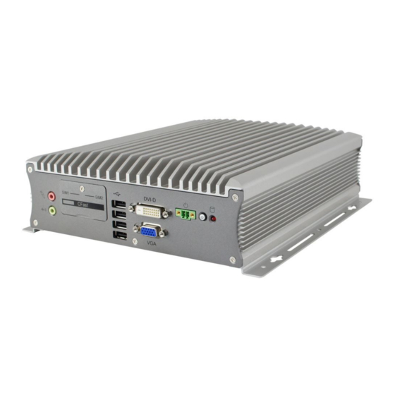
Page 19: Overview - Ami220
VGA Port (red for Mic-In, green for Line- Out) Terminal Block for Remote CFast & SIM Card Slots Power Button (2 pins) USB 2.0 Ports Power Button DVI-D Port LED Indicator for HDD AMI220 / 221 / 222 User Manual... - Page 20 Rear View No. Name Name DC-In Power Connector LAN Ports (3 pins) COM Ports Wall Mount Brackets (COM1 RS-232/422/485, COM2/3/4 RS-232) DisplayPorts Antenna Holes USB 3.0 Ports Oblique View AMI220 / 221 / 222 User Manual...
-
Page 21: Overview - Ami221
(red for Mic-In, green for Line- Power Button (2 pins) Out) CFast & SIM Card Slots Power Button USB 2.0 Ports LED Indicator for HDD DVI-D Port SSD Drive Bay VGA Port Oblique View AMI220 / 221 / 222 User Manual... - Page 22 Compatible Expansion Cards: Name Features IP214 1 x PCIe (x16), 2 x COM (COM5 & COM6), 2 x USB 2.0 IP215 1 x PCI, 2 x COM (COM5 & COM6), 2 x USB 2.0 AMI220 / 221 / 222 User Manual...
-
Page 23: Overview - Ami222
Power Button (2 pins) Out) CFast & SIM Card Slots Power Button USB 2.0 Ports LED Indicator for HDD DVI-D Port SSD Drive Bay Doors for Fieldbus Module VGA Port (Optional) Oblique View AMI220 / 221 / 222 User Manual... - Page 24 1 x PCIe (x16), 2 x COM (COM5 & COM6), 1 x SATA II, 2 x USB 2.0 IP212 IP213 1 x PCI, 1 x PCIe (x16), 1 x SATA III, 2 x USB 2.0 AMI220 / 221 / 222 User Manual...
-
Page 25: Dimensions - Ami220
General Information 1.11 Dimensions – AMI220 Unit: mm AMI220 / 221 / 222 User Manual... -
Page 26: Dimensions - Ami221
1.12 Dimensions – AMI221 Unit: mm AMI220 / 221 / 222 User Manual... -
Page 27: Dimensions - Ami222
General Information 1.13 Dimensions – AMI222 Unit: mm AMI220 / 221 / 222 User Manual... -
Page 28: Chapter 2 Hardware Configuration
Chapter 2 Hardware Configuration The information provided in this chapter includes: Essential installations before you begin • Information and locations of connectors •... -
Page 29: Essential Installations Before You Begin
I/O cover first and then removing 8 screws as shown below. After installation, secure the intermediate plate and the device bottom cover back. AMI220 / 221 / 222 User Manual... -
Page 30: Memory Installation
2. Insert the module slantwise and gently push the module straight down until the clips of the slot close to hold the module in place when the module touches the bottom of the slot. To remove the module, press the clips outwards with both hands. AMI220 / 221 / 222 User Manual... -
Page 31: Ssd Installation
(This is illustrated by the example of AMI221.) 1. Loosen 4 screws, take out the original 2.5” SSD and attach a new one after you disassemble the device bottom cover. 2. Secure the SSD with the 4 screws mentioned above. AMI220 / 221 / 222 User Manual... - Page 32 2. Install your 2.5” SSD onto the tray, and secure the SSD with the supplied 4 screws for the tray. Tray 4 screws 3. Put and secure the tray back to the device. AMI220 / 221 / 222 User Manual...
-
Page 33: Cfast & Micro-Sim Card Installation
CFast & micro-SIM card door. Then refer to 2.1.4 Mini-PCIe Network Cards Installation for further installation. To remove the micro-SIM card, push the card again. AMI220 / 221 / 222 User Manual... -
Page 34: Mini-Pcie Network Cards Installation
1. Locate the mini-PCIe slot, align the key of the mini-PCIe card to the interface, and insert the card slantwise. 2. Push the mini-PCIe card down, fix it with the supplied 2 flat head screws for full-sized card and with one screw for half-sized card. AMI220 / 221 / 222 User Manual... -
Page 35: Wifi / 3G / 4G Antenna Installation
Info: The diameter of the nut is around 6.35 mm (0.25”-36UNC). 2.1.6 Expansion Card Installation AMI221 and AMI222 support an expansion card slot while AMI220 does not feature any expansion slot. For AMI221, loosen a screw to remove the expansion filler. Then install the expansion card and fix the card with the screw. - Page 36 For AMI222, loosen 2 screws from the rear I/O cover to disassemble the USB double stack. Then release two screws to remove the expansion fillers and then install the expansion cards. Secure the cards with the 2 screws. AMI220 / 221 / 222 User Manual...
-
Page 37: Wall Mount Installation
The method of mounting must be able to support weight of the AMI220 plus the suspension weight of all the cables to be attached to the system. Use the following methods for mounting... - Page 38 2. Prepare at least 4 screws (M3) to install the device on wall . You can install AMI220 on plastic (LCD monitor), wood, drywall surface over studs, or a solid concrete or metal plane directly. The types of fasteners required are dependent on the type of wall construction.
-
Page 39: Pinout For Com Ports, Dc-In & Power Button Connectors
• Assigment Assigment DCD, Data carrier detect DSR, Data set ready RXD, Receive data RTS, Request to send TXD, Transmit data CTS, Clear to send DTR, Data terminal ready RI, Ring indicator Ground AMI220 / 221 / 222 User Manual... - Page 40 NC, No Connection NC, No Connection Ground DC-In Power Connector (terminal block) • Assigment Assigment 12V ~ 24V Power Ground Case Ground Remote Control Connector (terminal block) • Assigment Assigment Power BTN Ground AMI220 / 221 / 222 User Manual...
-
Page 41: Setting The Jumpers
When two pins of a jumper are encased in a jumper cap, this jumper is closed, i.e. turned On. When a jumper cap is removed from two jumper pins, this jumper is open, i.e. turned Off. AMI220 / 221 / 222 User Manual... -
Page 42: Jumper & Connector Locations On Motherboard
2.3 Jumper & Connector Locations on Motherboard Motherboard: MB220 CN13 CN12 CN11 CN10 CPU_FAN1 JBAT2 143 145 J4 J3 LED1 MB220 – top AMI220 / 221 / 222 User Manual... - Page 43 Hardware Configuration ® Intel Intel ® Gen. Core™ Q170 / H110 i7/i5/i3 Desktop Processor 146 144 CN15 CN14 MB220 - bottom AMI220 / 221 / 222 User Manual...
-
Page 44: Jumpers Quick Reference
JBAT2 CPU dGfx Bifurcation Selection JP2, JP3 COM1 & COM2 RS-232 Power Selection JP4, JP5 Factory Use Only 2.4.1 RTC Content Clearance (JBAT1) Function Pin closed Illustration Normal Open (default) Clear RTC Close AMI220 / 221 / 222 User Manual... -
Page 45: Cmos Data Clearance (Jbat2)
Hardware Configuration 2.4.2 CMOS Data Clearance (JBAT2) Function Pin closed Illustration Normal (default) Clear CMOS AMI220 / 221 / 222 User Manual... -
Page 46: Cpu Dgfx Bifurcation Selection (Jp2, Jp3)
Pin closed Illustration JP2: Open 1 x 16 (default) JP3: Open JP2: Close 2 x 8 JP3: Open JP2: Open RSVD JP3: Close JP2: Close x 8, x 4, x 4 JP3: Close AMI220 / 221 / 222 User Manual... -
Page 47: Com1 & Com2 Rs-232 Power Selection (Jp4, Jp5)
Hardware Configuration 2.4.4 COM1 & COM2 RS-232 Power Selection (JP4, JP5) JP4: COM1 JP5: COM2 Function Pin closed Illustration (default) AMI220 / 221 / 222 User Manual... -
Page 48: Connectors Quick Reference
J6, J7 PCIE (x1) & PCIE (x16) Slots PCIE1, PCIE2 J2, J3, J4, J8, J16, Factory Use Only [1], [2], [3] : Refer to 2.1.8 Pinout for COM Ports, DC-In & Power Button Connectors. AMI220 / 221 / 222 User Manual... -
Page 49: Reset Button Connector (J1)
Hardware Configuration 2.5.1 Reset Button Connector (J1) Assignment Assignment Reset BTN Ground AMI220 / 221 / 222 User Manual... -
Page 50: Sata Power Connector (J10, J11)
2.5.2 SATA Power Connector (J10, J11) Assignment Assignment Ground Ground AMI220 / 221 / 222 User Manual... -
Page 51: Com3 & Com4 Ports (J12, J9)
COM3 & COM4 Ports (J12, J9) J12: Assignment Assignment DCD, Data carrier detect RXD, Receive data TXD, Transmit data Data terminal ready Ground DSR, Data set ready RTS, Request to send CTS, Clear to send RI, Ring indicator AMI220 / 221 / 222 User Manual... -
Page 52: Digital I/O Connector (J13)
2.5.4 Digital I/O Connector (J13) Assignment Assignment Ground VCC5 OUT3 OUT1 OUT2 OUT0 AMI220 / 221 / 222 User Manual... -
Page 53: Cpu Fan Power Connector (Cpu_Fan1)
Hardware Configuration 2.5.5 CPU Fan Power Connector (CPU_FAN1) Assignment Assignment Ground Rotation detection Control AMI220 / 221 / 222 User Manual... -
Page 54: Chapter 3 Driver Installation
Chapter 3 Driver Installation The information provided in this chapter includes: ® Intel Chipset Software Installation Utility • Graphics Driver Installation • HD Audio Driver Installation • LAN Driver Installation • ® Intel Management Engine Driver Installation • USB 3.1 Driver Installation •... -
Page 55: Introduction
INF files for Plug & Play function for the chipset components. Follow the instructions below to complete the installation. 1. Insert the disk enclosed in the package. Click Intel and then Intel(R) Skylake Chipset Drivers. 2. Click Intel(R) Chipset Software Installation Utility. AMI220 / 221 / 222 User Manual... -
Page 56: Graphics Driver Installation
3. When the Welcome screen appears, click Next to continue. 4. Agree with the license agreement and click Install for installation. 5. When the driver has been completely installed, restart the computer for changes to take effect. AMI220 / 221 / 222 User Manual... -
Page 57: Hd Audio Driver Installation
2. Click Realtek High Definition Audio Driver. 3. On the Welcome screen of the InstallShield Wizard, click Next for installation. 4. When the driver has been completely installed, restart the computer for changes to take effect. AMI220 / 221 / 222 User Manual... -
Page 58: Lan Driver Installation
1. Insert the disk enclosed in the package with the product. Click LAN Card and then Intel(R) Skylake Chipset Drivers 2. Click Intel(R) PRO LAN Network Drivers.. 3. Click Install Drivers and Software.. AMI220 / 221 / 222 User Manual... -
Page 59: Intel Management Engine Driver Installation
8. As the driver has been completely installed, restart the computer for changes to take effect. ® 3.6 Intel Management Engine Driver Installation 1. Insert the disk enclosed in the package. Click Intel and then Intel(R) Skylake Chipset Drivers. AMI220 / 221 / 222 User Manual... - Page 60 3. When the Welcome screen appears, click Next to continue. 4. Accept the licence agreement and click Next to continue. 5. As the driver has been completely installed, restart the computer for changes to take effect. AMI220 / 221 / 222 User Manual...
-
Page 61: Usb 3.1 Driver Installation
Skylake Chipset Drivers. 2. Click ASMedia USB 3.1 Drivers. 3. When the Welcome screen appears, click Next to continue. 4. When the driver has been completely installed, restart the computer for changes to take effect. AMI220 / 221 / 222 User Manual... -
Page 62: Chapter 4 Bios Setup
Chapter 4 BIOS Setup This chapter describes the different settings available in the AMI BIOS that comes with the board. The topics covered in this chapter are as follows: Main Settings • Advanced Settings • Chipset Settings • Security Settings •... -
Page 63: Introduction
These defaults have been carefully chosen by both AMI and your system manufacturer to provide the absolute maximum performance and reliability. Changing the defaults could make the system unstable and crash in some cases. AMI220 / 221 / 222 User Manual... -
Page 64: Main Settings
Choose the system default language. System Date Sets the date. Use the <Tab> key to switch between the data elements. System Time Set the time. Use the <Tab> key to switch between the data elements. AMI220 / 221 / 222 User Manual... -
Page 65: Advanced Settings
BIOS Setup 4.4 Advanced Settings This section allows you to configure, improve your system and allows you to set up some system features according to your preference. AMI220 / 221 / 222 User Manual... -
Page 66: Trusted Computing
Trusted Computing BIOS Setting Description Security Device Support Enables / Disables BIOS support for security device. The operating system will not show security device. TCG EFI protocol and INT1A interface will not be available. AMI220 / 221 / 222 User Manual... -
Page 67: Acpi Settings
(OS/S4 Sleep State). This option may not be effective with some OS. ACPI Sleep State Selects a ACPI sleep state for the system to enter. Options: Suspend Disabled S3 (Suspend to RAM) AMI220 / 221 / 222 User Manual... -
Page 68: Ismart Controller
For example, if setting up a schedule from Wednesday 5 p.m. to Thursday 2 a.m., configure two schedule slots. But if setting up a schedule from 3 p.m to 5 p.m. on Wednesday, configure only a schedule slot. AMI220 / 221 / 222 User Manual... -
Page 69: Amt Configuration
Triggers CIRA boot. Assistance Process USB Configure Enables / Disables USB configure function. PET Progress Enables / Disables PET events progress to receive PET events or not. WatchDog Enables / Disables watchdog timer. AMI220 / 221 / 222 User Manual... -
Page 70: F81846 Super Io Configuration
Super IO device. 4.4.5.1. Serial Port 1 Configuration BIOS Setting Description Change Settings Selects an optimal settings for the Super I/O device. Device Mode Changes the mode of serial port. AMI220 / 221 / 222 User Manual... -
Page 71: F81846 Hardware Monitor
80 °C, 85 °C, 90 °C, 95 °C Temperatures / Voltages These fields are the parameters of the hardware monitoring function feature of the motherboard. The values are read-only as monitored by the system and showing the PC health status AMI220 / 221 / 222 User Manual... -
Page 72: Cpu Configuration
CPPC v2 interface to allow for hardware contorlled P-states. Intel(R) SpeedStep (tm) Enables / Disables the function to allow more than two frequency ranges to be supported. Turbo Mode Enables / Disables Turbo Mode. AMI220 / 221 / 222 User Manual... -
Page 73: Sata Configuration
SATA Mode Selection Selects IDE / AHCI Mode. Serial ATA Port 0~5 Enables / Disables Serial Port 0 ~ 5. SATA Port 0 ~ 5 HotPlug Enables / Disables SATA Port 0 ~ 5 HotPlug. AMI220 / 221 / 222 User Manual... -
Page 74: Csm Configuration
4.4.9 CSM Configuration BIOS Setting Description Network Controls the execution of UEFI and Legacy PXE OpROM. AMI220 / 221 / 222 User Manual... -
Page 75: Usb Configuration
Sets the time-out value 1, 5, 10 or 20 sec(s) for Control, Bulk, and Interrupt transfers. Device reset time-out Sets the seconds (10, 20, 30, 40 secs) of delaying execution of start unit command to USB mass storage device. AMI220 / 221 / 222 User Manual... - Page 76 The maximum time the device will take before it properly reports itself to the Host Controller. Auto uses default value. For a Root port, it is 100 ms. For a Hub port, the delay is taken from Hub descriptor. AMI220 / 221 / 222 User Manual...
-
Page 77: Chipset Settings
BIOS Setup 4.5 Chipset Settings BIOS Setting Description System Agent (SA) System Agent (SA) parameters Configuration PCH-IO Configuration PCH parameters AMI220 / 221 / 222 User Manual... -
Page 78: System Agent (Sa) Configuration
4.5.1 System Agent (SA) Configuration BIOS Setting Description VT-d Checks if VT-d function on MCH is supported. Graphics Configuration Configures the graphics settings. Memory Configuration Displays the memory configuration parameters. AMI220 / 221 / 222 User Manual... - Page 79 DVMT Pre-Allocated Sets DVMT 5.0 pre-allocated (fixed) graphics memory size used by the internal graphics devce. DVMT Total Gfx Mem Selects DVMT 5.0 total graphic memory size used by the internal graphcis device. AMI220 / 221 / 222 User Manual...
-
Page 80: Pch-Io Configuration
PCH LAN Controller Enables / Disables onboard NIC. Wake on LAN Enables / Disables integrated LAN to wake the system. (The Wake on LAN cannot be disabled if ME is at Sx state.) AMI220 / 221 / 222 User Manual... -
Page 81: Security Settings
BIOS Setup 4.6 Security Settings BIOS Setting Description Administrator Password Sets an administrator password for the setup utility. User Password Sets a user password. AMI220 / 221 / 222 User Manual... -
Page 82: Boot Settings
Has no effect for BBS boot options. Boot mode select Selects a Boot mode, Legacy / UEFI. Boot Option Priorities Sets the system boot order priorities for hard disk, CD/DVD, USB, Network. AMI220 / 221 / 222 User Manual... -
Page 83: Save & Exit Settings
Restores / Loads defaults values for all the setup options. Save as User Defaults Saves the changes done so far as user defaults. Restore User Defaults Restores the user defaults to all the setup options. AMI220 / 221 / 222 User Manual... -
Page 84: Appendix
Appendix This section provides the mapping addresses of peripheral devices and the sample code of watchdog timer configuration. Compatible Expansion Cards for AMI221 & AMI222 • I/O Port Address Map • Interrupt Request Lines (IRQ) • Watchdog Timer Configuration •... -
Page 85: Compatible Expansion Cards For Ami221 & Ami222
IP214 1 x PCIe (x16), 2 x COM (COM5 & COM6), 2 x USB 2.0 AMI221 IP215 1 x PCI, 2 x COM (COM5 & COM6), 2 x USB 2.0 AMI221 Expansion Cards Overview IP211 IP212 IP213 AMI220 / 221 / 222 User Manual... - Page 86 IP214 IP215 AMI220 / 221 / 222 User Manual...
-
Page 87: I/O Port Address Map
Motherboard resources 0x0000164E-0x0000164F Motherboard resources 0x00000020-0x00000021 Programmable interrupt controller 0x00000024-0x00000025 Programmable interrupt controller 0x00000028-0x00000029 Programmable interrupt controller 0x0000002C-0x0000002D Programmable interrupt controller 0x00000030-0x00000031 Programmable interrupt controller 0x00000034-0x00000035 Programmable interrupt controller 0x00000038-0x00000039 Programmable interrupt controller AMI220 / 221 / 222 User Manual... - Page 88 System timer 0x00001854-0x00001857 Motherboard resources 0x00000000-0x00000CF7 PCI Express Root Complex 0x00000D00-0x0000FFFF PCI Express Root Complex 0x0000F0A0-0x0000F0A7 Intel(R) Active Management Technology - SOL (COM7) 0x0000F000-0x0000F03F Intel(R) HD Graphics 630 0x000003B0-0x000003BB Intel(R) HD Graphics 630 AMI220 / 221 / 222 User Manual...
- Page 89 Motherboard resources 0x0000F040-0x0000F05F Intel(R) 100 Series/C230 Series Chipset Family SMBus - A123 0x00000060-0x00000060 Standard PS/2 Keyboard 0x00000064-0x00000064 Standard PS/2 Keyboard 0x0000D000-0x0000DFFF Intel(R) 100 Series/C230 Series Chipset Family PCI Express Root Port #7 - A116 AMI220 / 221 / 222 User Manual...
-
Page 90: Interrupt Request Lines (Irq)
Intel(R) I211 Gigabit Network Connection #2 IRQ 4294967290 IRQ 4294967291 Intel(R) USB 3.0 eXtensible Host Controller - 1.0 (Microsoft) IRQ 4294967292 Intel(R) HD Graphics 630 IRQ 4294967293 Intel(R) Ethernet Connection (2) I219-LM IRQ 4294967294 Standard SATA AHCI Controller AMI220 / 221 / 222 User Manual... -
Page 91: Watchdog Timer Configuration
81866 watch dog program\n"); SIO = Init_F81866(); if (SIO == 0) printf("Can not detect Fintek 81866, program abort.\n"); return(1); }//if (SIO == 0) if (argc != 2) printf(" Parameter incorrect!!\n"); return (1); AMI220 / 221 / 222 User Manual... - Page 92 Set_F81866_LD(0x07); //switch to logic device 7 bBuf = Get_F81866_Reg(0xFA); bBuf &= ~0x01; Set_F81866_Reg(0xFA, bBuf); //disable WDTO output bBuf = Get_F81866_Reg(0xF5); bBuf &= ~0x20; bBuf |= 0x40; Set_F81866_Reg(0xF5, bBuf); //disable WDT //--------------------------------------------------------------------------- AMI220 / 221 / 222 User Manual...
- Page 93 Init_Finish; } F81866_BASE = 0x00; result = F81866_BASE; Init_Finish: return (result); //--------------------------------------------------------------------------- void Unlock_F81866 (void) outportb(F81866_INDEX_PORT, F81866_UNLOCK); outportb(F81866_INDEX_PORT, F81866_UNLOCK); //--------------------------------------------------------------------------- void Lock_F81866 (void) outportb(F81866_INDEX_PORT, F81866_LOCK); //--------------------------------------------------------------------------- void Set_F81866_LD( unsigned char LD) Unlock_F81866(); AMI220 / 221 / 222 User Manual...
- Page 94 #define F81866_REG_LD 0x07 //--------------------------------------------------------------------------- #define F81866_UNLOCK 0x87 #define F81866_LOCK 0xAA //--------------------------------------------------------------------------- unsigned int Init_F81866(void); void Set_F81866_LD( unsigned char); void Set_F81866_Reg( unsigned char, unsigned char); unsigned char Get_F81866_Reg( unsigned char); //--------------------------------------------------------------------------- #endif // F81866_H AMI220 / 221 / 222 User Manual...
Need help?
Do you have a question about the AMI220 and is the answer not in the manual?
Questions and answers