
Related Manuals for IBASE Technology AMI221


Summary of Contents for IBASE Technology AMI221
- Page 1 AMI220 AMI221 AMI222 High Performance Fanless System User’s Manual Version 1.2 (September 2020)
- Page 2 No part of this publication may be reproduced, copied, stored in a retrieval system, translated into any language or transmitted in any form or by any means, electronic, mechanical, photocopying, or otherwise, without the prior written consent of IBASE Technology, Inc. (hereinafter referred to as “IBASE”).
- Page 3 Compliance This product has passed CE tests for environmental specifications and limits. This product is in accordance with the directives of the Union European (EU). If users modify and/or install other devices in this equipment, the CE conformity declaration may no longer apply. This product has been tested and found to comply with the limits for a Class B device, pursuant to Part 15 of the FCC Rules.
- Page 4 Important Safety Information Carefully read the precautions before using the device. Environmental conditions: Lay the device horizontally on a stable and solid surface in case the device may fall, causing serious damage. Make sure you leave plenty of space around the device for ventilation. ...
- Page 5 CAUTION Replace only with the same or equivalent type recommended by the manufacturer. Dispose of used batteries according to the manufacturer’s instructions. Warranty Policy IBASE standard products: 24-month (2-year) warranty from the date of shipment. If the date of shipment cannot be ascertained, the product serial numbers can be used to determine the approximate shipping date.
-
Page 6: Table Of Contents
Specifications – AMI222 ................9 Product View – AMI220 ................11 Product View – AMI221 ................13 1.10 Product View – AMI222 ................15 1.11 Dimensions – AMI220 ................17 ... - Page 7 Connectors Quick Reference ..............40 2.5.1 Reset Button Connector (J1) ..........41 2.5.2 SATA Power Connector (J10, J11) ........42 2.5.3 COM3 & COM4 Ports (J12, J9) ..........43 2.5.4 Digital I/O Connector (J13) .............
- Page 8 Appendix ....................... 76 Compatible Expansion Cards for AMI221 & AMI222 ....... 77 I/O Port Address Map ................79 Interrupt Request Lines (IRQ) ..............82 Watchdog Timer Configuration ..............83 viii AMI220 / 221 / 222 User Manual...
-
Page 9: Chapter 1 General Information
Chapter 1 General Information The information provided in this chapter includes: Features Packing List Optional Accessories Specifications Product View Dimensions... -
Page 10: Introduction
1.1 Introduction The AMI220 / AMI221 / AMI222 is an embedded computing system series designed for thin clients, smart industrial automation or controller, and retail ® equipment. It is a compact and fanless design with an Intel Gen. Core™ i7 / i5 / i3 processor. This product series also features iSmart that allows auto-on scheduling for general applications and energy savings. -
Page 11: Packing List
Round Head Screw (for 2 memory, if not pre-installed) Round Head Screw (for Mini PCIe card) Disk (including drivers and this user manual) AMI221 AMI221 Power Cord Terminal Block for DC-In Power Adapter (3 pins) ... -
Page 12: Optional Accessories
IBASE provide optional accessories as follows. Please contact us or your dealer if you need any. AMI220 DC-In Power Adapter WiFi Antenna Kit AMI221 DC-In Power Adapter WiFi Antenna Kit Expansion Kit (with 2 cables for COM5 & COM6 ports): IP214, IP215 AMI222 ... -
Page 13: Specifications - Ami220
General Information 1.5 Specifications – AMI220 Product Name AMI220 System Motherboard MB220AF MB220EF Windows10 (64-bit) / 7 (32-bit & 64-bit) Operating System Linux Ubuntu / Fedora 24 ® Intel Gen. Core™ i7 / i5 / i3 Desktop Processor TDP = 35W CPU Speed Up to 3.4 GHz... - Page 14 Product Name AMI220 Motherboard MB220AF MB220EF 2 x RJ45 GbE LAN 4 x USB 3.0 4 x USB 2.0 4 x COM ports: Serial COM1: RS-232/422/485, selectable from BIOS COM2/3/4: RS-232 only Digital I/O 4-In & 4-Out (Optional) 1 x DVI-D Display 1 x VGA...
-
Page 15: Specifications - Ami221
General Information 1.6 Specifications – AMI221 Product Name AMI221 System Motherboard MB220AF MB220EF Windows10 (64-bit) / 7 (32-bit & 64-bit) Operating System Linux Ubuntu / Fedora 24 ® Intel Gen. Core™ i7 / i5 / i3 Desktop Processor TDP = 35W Up to 3.4 GHz... - Page 16 Product Name AMI221 Motherboard MB220AF MB220EF 2 x RJ45 GbE LAN 4 x USB 3.0 4 x USB 2.0 6 x COM ports: COM1: RS-232/422/485, selectable from BIOS COM2/3/4: RS-232 only Serial COM5 & COM6: Simplified RS-232 with only RX, TX and Ground pins.
-
Page 17: Specifications - Ami222
General Information 1.7 Specifications – AMI222 Product Name AMI222 System Motherboard MB220AF MB220EF Windows10 (64-bit) / 7 (32-bit & 64-bit) Operating System Linux Ubuntu / Fedora 24 ® Intel Gen. Core™ i7 / i5 / i3 Desktop Processor TDP = 35W Up to 3.4 GHz CPU Speed... - Page 18 Product Name AMI222 Motherboard MB220AF MB220EF 4 x USB 3.0 4 x USB 2.0 (2 extra ports are applicable from the optional expansion cards IP211 / IP212 / IP213.) 4 ~ 6 x COM ports: COM1: RS-232/422/485, selectable from BIOS ...
-
Page 19: Product View - Ami220
General Information 1.8 Product View – AMI220 Front View No. Name Name Audio Jacks VGA Port (red for Mic-In, green for Line-Out) Terminal Block for Remote SIM Card Slots Power Button (2 pins) USB 2.0 Ports Power Button DVI-D Port LED Indicator for HDD AMI220 / 221 / 222 User Manual... - Page 20 Rear View No. Name Name DC-In Power Connector LAN Ports (3 pins) COM Ports Wall Mount Brackets (COM1 RS-232/422/485, COM2/3/4 RS-232) DisplayPorts Antenna Holes USB 3.0 Ports Oblique View AMI220 / 221 / 222 User Manual...
-
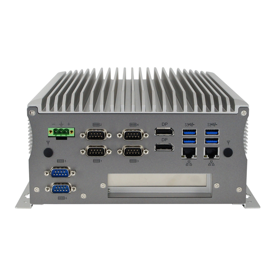
Page 21: Product View - Ami221
General Information 1.9 Product View – AMI221 Front View No. Name Name Audio Jacks (red for Mic-In, Terminal Block for Remote green for Line-Out) Power Button (2 pins) SIM Card Slots Power Button USB 2.0 Ports LED Indicator for HDD... - Page 22 Rear View No. Name Name DC-In Power Connector (3 pins) Wall Mount Brackets COM1 ~ COM4 Ports Antenna Holes (COM1 RS-232/422/485, COM2/3/4 RS-232) DisplayPorts Expansion Slot COM5 & COM6 Simplified USB 3.0 Ports RS-232 Ports LAN Ports [1]: Derived from the optional expansion card IP214 / IP215. Compatible Expansion Cards: Name Features...
-
Page 23: Product View - Ami222
General Information 1.10 Product View – AMI222 Front View No. Name Name Audio Jack (red for Mic-In, Terminal Block for Remote green for Line-Out) Power Button (2 pins) SIM Card Slots Power Button USB 2.0 Ports LED Indicator for HDD DVI-D Port SSD Drive Bay Doors for Fieldbus Module... - Page 24 Rear View No. Name Name DC-In Power Connector (3 pins) Wall Mount Brackets COM1 ~ COM4 Ports Antenna Holes (COM1 RS-232/422/485, COM2/3/4 RS-232) DisplayPorts Expansion Slots USB 2.0 Ports USB 3.0 Ports (*Available only for AMI222 with MB220AF) COM5 & COM6 Simplified LAN Ports RS-232 Ports [1]:...
-
Page 25: Dimensions - Ami220
General Information 1.11 Dimensions – AMI220 Unit: mm AMI220 / 221 / 222 User Manual... -
Page 26: Dimensions - Ami221
1.12 Dimensions – AMI221 Unit: mm AMI220 / 221 / 222 User Manual... -
Page 27: Dimensions - Ami222
General Information 1.13 Dimensions – AMI222 Unit: mm AMI220 / 221 / 222 User Manual... -
Page 28: Chapter 2 Hardware Configuration
Chapter 2 Hardware Configuration The information provided in this chapter includes: Essential installations before you begin Information and locations of connectors... -
Page 29: Essential Installations Before You Begin
Release 12 screws to disassemble the device bottom cover. For slots inside the AMI221 & AMI222, you also need to disassemble the intermediate plate by removing the front I/O cover first and then removing 8 screws as shown below. -
Page 30: Memory Installation
2.1.1 Memory Installation If you need to replace or install the memory modules, perform the following steps. 1. Locate the memory slot and align the key of the memory module with that on the memory slot. 2. Insert the module slantwise and gently push the module straight down until the clips of the slot close to hold the module in place when the module touches the bottom of the slot. -
Page 31: Ssd Installation
AMI221 / AMI222 For the 1 (default) SSD: (This is illustrated by the example of AMI221.) 1. Loosen 4 screws, take out the original 2.5” SSD and attach a new one after you disassemble the device bottom cover. 2. Secure the SSD with the 4 screws mentioned above. - Page 32 For the 2 SSD: (This is illustrated by the example of AMI221.) 1. Release 2 screws to pull out the SSD tray. 2. Install your 2.5” SSD onto the tray, and secure the SSD with the supplied 4 screws for the tray.
-
Page 33: Micro-Sim Card Installation
2.1.3 Micro-SIM Card Installation This is illustrated by the example of AMI221. 1. Release a screw as shown below to open the Micro-SIM card slot door. Insert the card to one of the micro-SIM card slot and push the card by using your fingernail or a corner of the micro-SIM card door. -
Page 34: Mini-Pcie Network Cards Installation
2.1.4 Mini-PCIe Network Cards Installation This is illustrated by the example of AMI221. Before you start, firstly pay attention to the interrelation among the SIM card slots and mini-PCIe slots. 1. Locate the mini-PCIe slot, align the key of the mini-PCIe card to the interface, and insert the card slantwise. -
Page 35: Wifi / 3G / 4G Antenna Installation
AMI221 and AMI222 support an expansion card slot while AMI220 does not feature any expansion slot. For AMI221, loosen a screw to remove the expansion filler. Then install the expansion card and fix the card with the screw. AMI220 / 221 / 222 User Manual... - Page 36 For AMI222, loosen 2 screws from the rear I/O cover to disassemble the USB double stack. Then release two screws to remove the expansion fillers and then install the expansion cards. Secure the cards with the 2 screws. AMI220 / 221 / 222 User Manual...
-
Page 37: Wall Mount Installation
Hardware Configuration 2.1.7 Wall Mount Installation Note: Before mounting the system on wall, ensure that you are following all applicable building and electric codes. Requirements When mounting, ensure that you have enough room for power and signal cable routing, and have good ventilation for power adapter. The method of mounting must be able to support weight of the AMI220 plus the suspension weight of all the cables to be attached to the system. - Page 38 Wall mount installation instructions: This is illustrated by the example of AMI221. 1. Attach the mounting brackets to your product, and secure with the supplied 6 screws. 2. Prepare at least 4 screws (M3) to install the device on wall .
-
Page 39: Pinout For Com Ports, Dc-In & Power Button Connectors
Hardware Configuration 2.1.8 Pinout for COM Ports, DC-In & Power Button Connectors COM1 RS232/422/485 Port COM1 port is jumper-less and configurable in BIOS. Assigment Assigment DCD, Data carrier detect DSR, Data set ready RXD, Receive data RTS, Request to send TXD, Transmit data CTS, Clear to send DTR, Data terminal ready... - Page 40 COM5 / COM6 Simplified RS-232 Ports (with RX & TX only) COM5 and COM6 are both available for AMI221 via the expansion card IP214 / IP215 and available for AMI222 via IP211 / IP212. Assigment Assigment NC, No Connection...
-
Page 41: Setting The Jumpers
Hardware Configuration 2.2 Setting the Jumpers Set up and configure your device by using jumpers for various settings and features according to your needs and applications. Contact your supplier if you have doubts about the best configuration for your use. 2.2.1 How to Set Jumpers Jumpers are short-length conductors consisting of several metal pins with a... -
Page 42: Jumper & Connector Locations On Motherboard
2.3 Jumper & Connector Locations on Motherboard Motherboard: MB220 MB220 – top AMI220 / 221 / 222 User Manual... - Page 43 Hardware Configuration ® Intel Intel ® Gen. Core™ Q170 / H110 i7/i5/i3 Desktop Processor 146 144 CN15 CN14 MB220 - bottom AMI220 / 221 / 222 User Manual...
-
Page 44: Jumpers Quick Reference
2.4 Jumpers Quick Reference Function Connector Name Page RTC Content Clearance JBAT1 CMOS Data Clearance JBAT2 CPU dGfx Bifurcation Selection JP2, JP3 COM1 & COM2 RS-232 Power Selection JP4, JP5 Factory Use Only 2.4.1 RTC Content Clearance (JBAT1) Function Pin closed Illustration Normal Open... -
Page 45: Cmos Data Clearance (Jbat2)
Hardware Configuration 2.4.2 CMOS Data Clearance (JBAT2) Function Pin closed Illustration Normal (default) Clear CMOS AMI220 / 221 / 222 User Manual... -
Page 46: Cpu Dgfx Bifurcation Selection (Jp2, Jp3)
2.4.3 CPU dGfx Bifurcation Selection (JP2, JP3) Function Pin closed Illustration JP2: Open 1 x 16 (default) JP3: Open JP2: Close 2 x 8 JP3: Open JP2: Open RSVD JP3: Close JP2: Close x 8, x 4, x 4 JP3: Close AMI220 / 221 / 222 User Manual... -
Page 47: Com1 & Com2 Rs-232 Power Selection (Jp4, Jp5)
Hardware Configuration 2.4.4 COM1 & COM2 RS-232 Power Selection (JP4, JP5) JP4: COM1 JP5: COM2 Function Pin closed Illustration (default) AMI220 / 221 / 222 User Manual... -
Page 48: Connectors Quick Reference
2.5 Connectors Quick Reference Function Connector Name Page Reset Button Connector SATA Power Connector J10, J11 COM3 & COM4 Ports J12, J9 Digital I/O Connector CPU Fan Power Connector CPU_FAN1 DC-In Power Connector Audio Jacks USB 2.0 Quad Port VGA & DVI-D Ports Remote Control Connector SATA3 Port CN7, CN8... -
Page 49: Reset Button Connector (J1)
Hardware Configuration 2.5.1 Reset Button Connector (J1) Assignment Assignment Reset BTN Ground AMI220 / 221 / 222 User Manual... -
Page 50: Sata Power Connector (J10, J11)
2.5.2 SATA Power Connector (J10, J11) Assignment Assignment Ground Ground AMI220 / 221 / 222 User Manual... -
Page 51: Com3 & Com4 Ports (J12, J9)
Hardware Configuration 2.5.3 COM3 & COM4 Ports (J12, J9) Assignment Assignment DCD, Data carrier detect RXD, Receive data TXD, Transmit data Data terminal ready Ground DSR, Data set ready RTS, Request to send CTS, Clear to send RI, Ring indicator AMI220 / 221 / 222 User Manual... -
Page 52: Digital I/O Connector (J13)
2.5.4 Digital I/O Connector (J13) Assignment Assignment Ground VCC5 OUT3 OUT1 OUT2 OUT0 AMI220 / 221 / 222 User Manual... -
Page 53: Cpu Fan Power Connector (Cpu_Fan1)
Hardware Configuration 2.5.5 CPU Fan Power Connector (CPU_FAN1) Assignment Assignment Ground Rotation detection Control AMI220 / 221 / 222 User Manual... -
Page 54: Chapter 3 Driver Installation
Chapter 3 Driver Installation The information provided in this chapter includes: ® Intel Chipset Software Installation Utility Graphics Driver Installation HD Audio Driver Installation LAN Driver Installation ® Intel Management Engine Driver Installation USB 3.1 Driver Installation... -
Page 55: Introduction
Driver Installation 3.1 Introduction This section describes the installation procedures for software drivers. The software drivers are in a disk enclosed with the product package. If you find anything missing, please contact the distributor where you made the purchase. Note: After installing your Windows operating system, you must install the ®... -
Page 56: Graphics Driver Installation
® 3. When the Welcome screen to the Intel Chipset Device Software appears, click Next to continue. 4. Accept the software license agreement and proceed with the installation process. 5. On the Readme File Information screen, click Next for installation. 6. -
Page 57: Hd Audio Driver Installation
Driver Installation 3.4 HD Audio Driver Installation 1. Insert the disk enclosed in the package. Click Intel and then Intel(R) Skylate Chipset Drivers. 2. Click Realtek High Definition Audio Driver. 3. On the Welcome screen of the InstallShield Wizard, click Next for installation. 4. -
Page 58: Lan Driver Installation
3.5 LAN Driver Installation 1. Insert the disk enclosed in the package with the product. Click LAN Card and then Intel(R) Skylake Chipset Drivers 2. Click Intel(R) PRO LAN Network Drivers.. 3. Click Install Drivers and Software.. AMI220 / 221 / 222 User Manual... -
Page 59: Intel Management Engine Driver Installation
Driver Installation 4. When the Welcome screen appears, click Next to continue. 5. Accept the license agreement and click Next to continue. 6. Tick the checkbox for Drivers to select the related drivers and click Next. 7. When the wizard is ready for installation, click Install. 8. - Page 60 2. Click Intel(R) ME 11.x Drivers. 3. When the Welcome screen appears, click Next to continue. 4. Accept the licence agreement and click Next to continue. 5. As the driver has been completely installed, restart the computer for changes to take effect. AMI220 / 221 / 222 User Manual...
-
Page 61: Usb 3.1 Driver Installation
Driver Installation 3.7 USB 3.1 Driver Installation 1. Insert the disk enclosed in the package. Click Intel and then Intel(R) Skylake Chipset Drivers. 2. Click ASMedia USB 3.1 Drivers. 3. When the Welcome screen appears, click Next to continue. 4. When the driver has been completely installed, restart the computer for changes to take effect. -
Page 62: Chapter 4 Bios Setup
Chapter 4 BIOS Setup This chapter describes the different settings available in the AMI BIOS that comes with the board. The topics covered in this chapter are as follows: Main Settings Advanced Settings Chipset Settings Security Settings ... -
Page 63: Introduction
BIOS Setup 4.1 Introduction The BIOS (Basic Input/Output System) installed in the ROM of your computer system supports Intel® processors. The BIOS provides critical low-level support for standard devices such as disk drives, serial ports and parallel ports. It also provides password protection as well as special support for detailed fine-tuning of the chipset controlling the entire system. -
Page 64: Main Settings
4.3 Main Settings BIOS Setting Description System Language Choose the system default language. System Date Sets the date. Use the <Tab> key to switch between the data elements. System Time Set the time. Use the <Tab> key to switch between the data elements. -
Page 65: Advanced Settings
BIOS Setup 4.4 Advanced Settings This section allows you to configure, improve your system and allows you to set up some system features according to your preference. AMI220 / 221 / 222 User Manual... -
Page 66: Trusted Computing
4.4.1 Trusted Computing BIOS Setting Description Security Device Support Enables / Disables BIOS support for security device. The operating system will not show security device. TCG EFI protocol and INT1A interface will not be available. AMI220 / 221 / 222 User Manual... -
Page 67: Acpi Settings
BIOS Setup 4.4.2 ACPI Settings BIOS Setting Description Enable Hibernation Enables / Disables the system ability to hibernate (OS/S4 Sleep State). This option may not be effective with some OS. ACPI Sleep State Selects a ACPI sleep state for the system to enter. -
Page 68: Ismart Controller
4.4.3 iSmart Controller BIOS Setting Description Power-On after Power Enables / Disables the system to be turned on failure automatically after a power failure. Power Resume Delay Enables / Disables to delay the time for system to turn on. Temperature Guardian Generate the reset signal when system hands up on POST. -
Page 69: Amt Configuration
BIOS Setup 4.4.4 AMT Configuration BIOS Setting Description Intel AMT Enables / Disables Intel(R) Active Management Tecnology BIOS Extension. Note: iAMT H/W is alwas enabled. This option just controls the BIOS extension execution. If enabled, this requires additional firmware in the SPI device. BIOS Hotkey Pressed OEMFlag Bit 1: enables or disables BIOS hotkey press. -
Page 70: F81846 Super Io Configuration
4.4.5 F81846 Super IO Configuration BIOS Setting Description Serial Port Configuration Sets Parameters of Serial Ports. You can enable / disable the serial port and select an optimal settings for the Super IO device. 4.4.5.1. Serial Port 1 Configuration BIOS Setting Description Change Settings Selects an optimal settings for the Super I/O... -
Page 71: F81846 Hardware Monitor
BIOS Setup 4.4.6 F81846 Hardware Monitor BIOS Setting Description CPU Smart Fan Control Controls the CPU fan temperature by setting up a threashold temperature. Options: Disabled (default),. 50 °C, 60 °C, 70 °C, 80 °C CPU Shutdown This field enables or disables the Shutdown Temperature Temperature Options: Disabled (default),. -
Page 72: Cpu Configuration
4.4.7 CPU Configuration BIOS Setting Description Intel(R) Speed Shift Enables / Disabvbles Intel(R) Speed Shift Technology Technology support. Enabling will expose the CPPC v2 interface to allow for hardware contorlled P-states. Intel(R) SpeedStep (tm) Enables / Disables the function to allow more than two frequency ranges to be supported. -
Page 73: Sata Configuration
BIOS Setup 4.4.8 SATA Configuration BIOS Setting Description SATA Controller(s) Enables / Disables SATA device. SATA Mode Selection Selects IDE / AHCI Mode. Serial ATA Port 0~5 Enables / Disables Serial Port 0 ~ 5. SATA Port 0 ~ 5 HotPlug Enables / Disables SATA Port 0 ~ 5 HotPlug. -
Page 74: Csm Configuration
4.4.9 CSM Configuration BIOS Setting Description Network Controls the execution of UEFI and Legacy PXE OpROM. AMI220 / 221 / 222 User Manual... -
Page 75: Usb Configuration
BIOS Setup 4.4.10 USB Configuration BIOS Setting Description Legacy USB Support Enables / Disables Legacy USB support. Auto disables legacy support if there is no USB device connected. Disable keeps USB devices available only for EFI applications. XHCI Hand-pff This is a workaround for OSes without XHCI hand-off support. - Page 76 BIOS Setting Description Device power-up delay The maximum time the device will take before it properly reports itself to the Host Controller. Auto uses default value. For a Root port, it is 100 ms. For a Hub port, the delay is taken from Hub descriptor.
-
Page 77: Chipset Settings
BIOS Setup 4.5 Chipset Settings BIOS Setting Description System Agent (SA) System Agent (SA) parameters Configuration PCH-IO Configuration PCH parameters AMI220 / 221 / 222 User Manual... -
Page 78: System Agent (Sa) Configuration
4.5.1 System Agent (SA) Configuration BIOS Setting Description VT-d Checks if VT-d function on MCH is supported. Graphics Configuration Configures the graphics settings. Memory Configuration Displays the memory configuration parameters. AMI220 / 221 / 222 User Manual... - Page 79 BIOS Setup 4.5.1.1. Graphics Configuration BIOS Setting Description Graphics Turbo IMON Graphics turbo IMON current values supported Current (14-31). Skip Scanning of External If enabled, it will not scan for external Gfx Card Gfx Card on PEG and PCH PCIE ports. Primary Display Selects which of IGFX/PEG/PCI graphics device should be primary display, or selects SG...
-
Page 80: Pch-Io Configuration
4.5.1.2. Memory Configuration 4.5.2 PCH-IO Configuration BIOS Setting Description PCH LAN Controller Enables / Disables onboard NIC. Wake on LAN Enables / Disables integrated LAN to wake the system. (The Wake on LAN cannot be disabled if ME is at Sx state.) AMI220 / 221 / 222 User Manual... -
Page 81: Security Settings
BIOS Setup 4.6 Security Settings BIOS Setting Description Administrator Password Sets an administrator password for the setup utility. User Password Sets a user password. AMI220 / 221 / 222 User Manual... -
Page 82: Boot Settings
4.7 Boot Settings BIOS Setting Description Setup Prompt Timeout Number of seconds to wait for setup activation key. 65535 (0xFFFF) means indefinite waiting. Bootup NumLock State Selects the keyboard NumLock state. Quiet Boot Enables / Disables Quiet Boot option. Fast Boot Enables / Disables boot with initialization of a minimal set of devices required to launch the active boot option. -
Page 83: Save & Exit Settings
BIOS Setup 4.8 Save & Exit Settings BIOS Setting Description Save Changes and Exit Exits system setup after saving the changes. Discard Changes and Exit Exits system setup without saving any changes. Save Changes and Reset Resets the system after saving the changes. Discard Changes and Resets system setup without saving any Reset... -
Page 84: Appendix
Appendix This section provides the mapping addresses of peripheral devices and the sample code of watchdog timer configuration. Compatible Expansion Cards for AMI221 & AMI222 I/O Port Address Map Interrupt Request Lines (IRQ) Watchdog Timer Configuration... -
Page 85: Compatible Expansion Cards For Ami221 & Ami222
Appendix A. Compatible Expansion Cards for AMI221 & AMI222 The IBASE expansion cards compatible with AMI221 & AMI222 are as follows. Compatible Name Features System 1 x PCIe (x1), 1 x PCIe (x8), 2 x COM (COM5 & COM6), IP211 AMI222 1 x SATA II, 2 x USB 2.0... - Page 86 IP214 IP215 AMI220 / 221 / 222 User Manual...
-
Page 87: I/O Port Address Map
Appendix B. I/O Port Address Map Each peripheral device in the system is assigned a set of I/O port addresses which also becomes the identity of the device. The following table lists the I/O port addresses used. Address Device Description 0x00000A00-0x00000A0F Motherboard resources 0x00000A10-0x00000A1F... - Page 88 Address Device Description 0x0000003C-0x0000003D Programmable interrupt controller 0x000000A0-0x000000A1 Programmable interrupt controller 0x000000A4-0x000000A5 Programmable interrupt controller 0x000000A8-0x000000A9 Programmable interrupt controller 0x000000AC-0x000000AD Programmable interrupt controller 0x000000B0-0x000000B1 Programmable interrupt controller 0x000000B4-0x000000B5 Programmable interrupt controller 0x000000B8-0x000000B9 Programmable interrupt controller 0x000000BC-0x000000BD Programmable interrupt controller 0x000004D0-0x000004D1 Programmable interrupt controller 0x00000800-0x0000087F Motherboard resources...
- Page 89 Appendix Address Device Description 0x000003C0-0x000003DF Intel(R) HD Graphics 630 0x0000FF00-0x0000FFFE Motherboard resources 0x0000F040-0x0000F05F Intel(R) 100 Series/C230 Series Chipset Family SMBus - A123 0x00000060-0x00000060 Standard PS/2 Keyboard 0x00000064-0x00000064 Standard PS/2 Keyboard 0x0000D000-0x0000DFFF Intel(R) 100 Series/C230 Series Chipset Family PCI Express Root Port #7 - A116 AMI220 / 221 / 222 User Manual...
-
Page 90: Interrupt Request Lines (Irq)
C. Interrupt Request Lines (IRQ) Peripheral devices use interrupt request lines to notify CPU for the service required. The following table shows the IRQ used by the devices on board. Level Function IRQ 0 System timer IRQ 1 Standard PS/2 Keyboard IRQ 3 Communications Port (COM2) IRQ 4... -
Page 91: Watchdog Timer Configuration
Appendix D. Watchdog Timer Configuration The Watchdog Timer (WDT) is used to generate a variety of output signals after a user programmable count. The WDT is suitable for the use in the prevention of system lock-up, such as when software becomes trapped in a deadlock. - Page 92 printf("System will reset after %d seconds\n", bTime); if (bTime) EnableWDT(bTime); } else DisableWDT(); } return 0; //--------------------------------------------------------------------------- void EnableWDT(int interval) unsigned char bBuf; bBuf = Get_F81866_Reg(0x2B); bBuf &= (~0x20); Set_F81866_Reg(0x2B, bBuf); //Enable WDTO Set_F81866_LD(0x07); //switch to logic device 7 Set_F81866_Reg(0x30, 0x01); //enable timer bBuf = Get_F81866_Reg(0xF5);...
- Page 93 Appendix //--------------------------------------------------------------------------- // THIS CODE AND INFORMATION IS PROVIDED "AS IS" WITHOUT WARRANTY OF ANY // KIND, EITHER EXPRESSED OR IMPLIED, INCLUDING BUT NOT LIMITED TO THE // IMPLIED WARRANTIES OF MERCHANTABILITY AND/OR FITNESS FOR A PARTICULAR // PURPOSE. //--------------------------------------------------------------------------- #include "F81866.H"...
- Page 94 outportb(F81866_DATA_PORT, LD); Lock_F81866(); //--------------------------------------------------------------------------- void Set_F81866_Reg( unsigned char REG, unsigned char DATA) Unlock_F81866(); outportb(F81866_INDEX_PORT, REG); outportb(F81866_DATA_PORT, DATA); Lock_F81866(); //--------------------------------------------------------------------------- unsigned char Get_F81866_Reg(unsigned char REG) unsigned char Result; Unlock_F81866(); outportb(F81866_INDEX_PORT, REG); Result = inportb(F81866_DATA_PORT); Lock_F81866(); return Result; //--------------------------------------------------------------------------- //--------------------------------------------------------------------------- // THIS CODE AND INFORMATION IS PROVIDED "AS IS" WITHOUT WARRANTY OF ANY // KIND, EITHER EXPRESSED OR IMPLIED, INCLUDING BUT NOT LIMITED TO THE // IMPLIED WARRANTIES OF MERCHANTABILITY AND/OR FITNESS FOR A PARTICULAR // PURPOSE.
Need help?
Do you have a question about the AMI221 and is the answer not in the manual?
Questions and answers