
Related Manuals for IBASE Technology ASB200-919


Summary of Contents for IBASE Technology ASB200-919
- Page 1 ASB200-919 Fanless System with 3.5” Disk-Size SBC System User’s Manual Version 1.0a (February 2022)
- Page 2 No part of this publication may be reproduced, copied, stored in a retrieval system, translated into any language or transmitted in any form or by any means, electronic, mechanical, photocopying, or otherwise, without the prior written consent of IBASE Technology, Inc. (hereinafter referred to as “IBASE”).
- Page 3 0.1% by weight (1000 ppm) except for cadmium, limited to 0.01% by weight (100 ppm). • Lead (Pb) • Mercury (Hg) • Cadmium (Cd) • Hexavalent chromium (Cr6+) • Polybrominated biphenyls (PBB) • Polybrominated diphenyl ether (PBDE) ASB200-919 User Manual...
- Page 4 Do not disassemble, repair or make any modification to the device. Disassembly, modification, or any attempt at repair could generate hazards and cause damage to the device, even bodily injury or property damage, and will void any warranty. ASB200-919 User Manual...
- Page 5 Software in use (such as OS and application software, including the version numbers) 3. If repair service is required, you can download the RMA form at http://www.ibase.com.tw/english/Supports/RMAService/. Fill out the form and contact your distributor or sales representative. ASB200-919 User Manual...
-
Page 6: Table Of Contents
Battery Connector (J16) ............28 2.5.9 COM2, COM3, COM4 RS-232 Ports (J20, J21, J22) ....29 2.5.10 DC Power Input Connector (J18) .......... 29 2.5.11 Digital I/O Connector (J17) ............30 2.5.12 LCD Backlight Connector (J15) ..........30 ASB200-919 User Manual... - Page 7 Security Settings ..................65 Boot Settings..................66 Save & Exit Settings ................67 Appendix......................68 I/O Port Address Map ................69 Interrupt Request Lines (IRQ) ..............71 Digital I/O Sample Code ................. 72 Watchdog Timer Configuration ............... 76 ASB200-919 User Manual...
-
Page 9: Chapter 1 General Information
Chapter 1 General Information The information provided in this chapter includes: Features Packing List Optional Accessories Specifications Product View Dimensions ... -
Page 10: Introduction
Introduction ® The ASB200-919 is mini embedded system based on the Intel Gen. Core™ and Celeron processors and the IBASE IB919 series 3.5” disk-size SBC that supports two DDR4 memory slots with a capacity of 32GB. The compact and fanless design makes it suitable for smart retail, transportation, healthcare, and smart factory applications even in large field deployments. -
Page 11: Packing List
10-pin Terminal Block (for GPIO connector) Side Brackets Screws for Side Brackets Screws for M key and E key M.2 Power Adaptor and Power Cord Optional Accessories WiFi / Bluetooth Module Kit ASB200-919 User Manual... -
Page 12: Specifications
Specifications Product Name ASB200-919-i7 ASB200-919-i5 ASB200-919-i3 ASB200-919-CEL Motherboard IB919AF-8665 IB919AF-8365 IB919F-8145 IB919F-4305 System Windows 10 Operating System Linux Ubuntu / Fedora ® ® ® Intel Gen. Intel Gen. Intel Gen. ® Intel Gen. Core™ Core™ Core™ Celeron 4305U... - Page 13 Operating: 0.25 Grms / 5 ~ 500 Hz Vibration Protection Non-operating: 1 Grms / 5 ~ 500Hz Operating: 20 g / 11 ms Shock Protection Non-operating: 40 g / 11 ms All specifications are subject to change without prior notice. ASB200-919 User Manual...
-
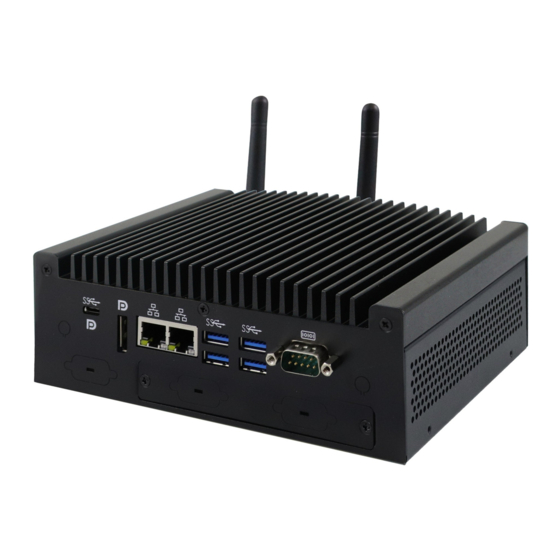
Page 14: Product View
Product View Front View Name Name Antenna Holes Power Switch Digital I/O (4-In / 4-Out) DC +12V~ +24V Power Input HDD LED ASB200-919 User Manual... - Page 15 General Information Rear View Name Name COM1 RS-232/422/485 Display Port / USB Type-C USB 3.0 Ports COM Port Holes LAN Port Antenna Holes Display Port ASB200-919 User Manual...
- Page 16 Oblique View ASB200-919 User Manual...
-
Page 17: Dimensions
General Information Dimensions Unit: mm ASB200-919 User Manual... -
Page 18: Chapter 2 Hardware Configuration
Chapter 2 Hardware Configuration The information provided in this chapter includes: Installations Descriptions and locations of connectors ... -
Page 19: Installations
If you need to install or replace an SSD or a HDD, follow the instructions below. 1. Remove the five screw shown below. Lift the hard drive cover and proceed to remove or install the SSD/HDD drive. ASB200-919 User Manual... -
Page 20: Card Installation
2.1.2 M.2 Card Installation 1. Remove the bottom chassis cover by loosening the 9 screws and the COM port standoff as indicated below. 2. Remove the 2 screws shown below and proceed to install the M.2 card. ASB200-919 User Manual... -
Page 21: Memory Installation
3. Gently push the module down in an upright position until the clips of the slot close to hold the module in place when the module touches the bottom of the slot. To remove the module, press the clips outwards with both hands, and the module will pop-up. ASB200-919 User Manual... -
Page 22: Wifi / 3G / 4G Antenna Installation
Thread the WiFi / 3G / 4G antenna cable through an antenna hole. Then fasten the antenna as shown below. Info: The diameter of the nut is around 6.35 mm (0.25”-36UNC). 2.1.5 Side Bracket Installation Use the screws provided in the accessory kit to lock the case together with the bracket ASB200-919 User Manual... -
Page 23: Pinout For Com Ports, Dc Power & Digital I/O Connectors
DCD, Data carrier detect DSR, Data set ready RXD, Receive data RTS, Request to send TXD, Transmit data CTS, Clear to send DTR, Data terminal ready RI, Ring indicator Ground Assignment RS-232 RS-422 RS-485 DATA- DATA+ Ground Ground Ground ASB200-919 User Manual... - Page 24 DC Power Input Connector (terminal block) Assignment Pin Assignment Ground +12V ~ +24V Chassis Ground Digital I/O Connector (terminal block) Pin Assignment Pin Assignment Ground ASB200-919 User Manual...
-
Page 25: Setting The Jumpers
1 2 3 When two pins of a jumper are encased in a jumper cap, this jumper is closed, i.e. turned On. When a jumper cap is removed from two jumper pins, this jumper is open, i.e. turned Off. ASB200-919 User Manual... -
Page 26: Jumper & Connector Locations On The Motherboard
Jumper & Connector Locations on the Motherboard Motherboard: IB919 ASB200-919 User Manual... -
Page 27: Jumpers Quick Reference
JBAT1 EDP Panel Power Selection JP3(For power) / LVDS Panel Power / Brightness Selections JP5 (For brightness) EDP / LVDS Selection Factory Use Only 2.4.1 Clear CMOS Data (JP2) Function Pin closed Illustration Normal (default) Clear CMOS ASB200-919 User Manual... -
Page 28: Edp Panel Power Selection (Jp2)
2.4.2 EDP Panel Power Selection (JP2) Jumper Function Pin closed Illustration 3.3V (default) ASB200-919 User Manual... -
Page 29: Lvds Panel Power / Brightness Selections (Jp3 / Jp5)
Hardware Configuration 2.4.3 LVDS Panel Power / Brightness Selections (JP3 / JP5) Jumper Function Pin closed Illustration 3.3V (default) 3.3V Open (default) Close ASB200-919 User Manual... -
Page 30: Edp / Lvds Selection (Jp4)
2.4.4 EDP / LVDS Selection (JP4) Jumper Function Pin closed Illustration (default) LVDS ASB200-919 User Manual... -
Page 31: Connectors Quick Reference
EDP Connector SATA III Port CN1, CN2 Display Port GbE LAN Ports USB 3.0 Port CN6, CN7 USB Type-C DDR4 SO-DIMM Slot J4, J7 M.2 E-Key / M.2 M-Key J8, J12 Factory Use Only J2, J19, J11 ASB200-919 User Manual... -
Page 32: Com1 Rs-232/422/485 Port (Cn9)
DCD, Data carrier detect DSR, Data set ready RXD, Receive data RTS, Request to send TXD, Transmit data CTS, Clear to send DTR, Data terminal ready RI, Ring indicator Ground Assignment RS-232 RS-422 RS-485 DATA- DATA+ Ground Ground Ground ASB200-919 User Manual... -
Page 33: Amplifier Connector (J1)
Hardware Configuration 2.5.2 Amplifier Connector (J1) Pin Assignment Pin Assignment SPK_L+ SPK_R- SPK_L- SPK_R+ 2.5.3 Audio Connector (J3) Pin Assignment Pin Assignment LINEOUT_L LINEOUT_R JD_FRONT Ground LINEIN_L LINEIN_R JD_LINEIN Ground MIC_L MIC-R JD_MIC1 Ground ASB200-919 User Manual... -
Page 34: Sata Hdd Power Connector (J5)
2.5.4 SATA HDD Power Connector (J5) Pin Assignment Pin Assignment Ground Ground +12V 2.5.5 SMBUS Connector (J10) Pin Assignment Pin Assignment +3.3V SMB_DATA SMB_CLK- Ground ASB200-919 User Manual... -
Page 35: Front Panel Connector (J9)
Orientation is not required when making a connection to this header. Power LED: Pins 7 and 8 This connector connects to the system power LED on control panel. This LED will light when the system turns on. ASB200-919 User Manual... -
Page 36: Usb 2.0 Connector (J6)
2.5.7 USB 2.0 Connector (J6) Pin Assignment Pin Assignment Ground Ground 2.5.8 Battery Connector (J16) Pin Assignment Battery+ Ground ASB200-919 User Manual... -
Page 37: Com2, Com3, Com4 Rs-232 Ports (J20, J21, J22)
TXD, Transmit data DTR, Data terminal ready Ground DSR, Data set ready RTS, Request to send CTS, Clear to send RI, Ring indicator Not Used 2.5.10 DC Power Input Connector (J18) Pin Assignment +12V ~ +24V Ground ASB200-919 User Manual... -
Page 38: Digital I/O Connector (J17)
2.5.11 Digital I/O Connector (J17) Pin Assignment Pin Assignment Ground OUT3 OUT1 OUT2 OUT0 2.5.12 LCD Backlight Connector (J15) Assignment Assignment +12V Brightness Control Backlight Enable Ground ASB200-919 User Manual... -
Page 39: Lvds Connector (J14, J13)
TX0P TX0N Ground Ground TX1P TX1N Ground Ground TX2P TX2N Ground Ground CLKP CLKN Ground Ground TX3P TX3N Power Power 2.5.14 CPU Fan Connector (CPU_FAN1) Pin Assignment Pin Assignment Ground CPU Fan In +12V CPU Fan Out ASB200-919 User Manual... -
Page 40: Edp Connector (Cn3)
VCC Ground eDP VCC AUXP eDP VCC AUXN Ground Ground +3.3V Ground +12V Ground Hot Plug detect Ground Ground TXN3 TXP3 Back Light Control Ground Back Lignt Enable TXN2 +12V TXP2 +3.3V Ground Ground TXN1 TXP1 Ground ASB200-919 User Manual... -
Page 41: Chapter 3 Driver Installation
Chapter 3 Driver Installation The information provided in this chapter includes: ® Intel Chipset Software Installation Utility Graphics Driver Installation HD Audio Driver Installation LAN Driver Installation ® Intel Management Engine Driver Installation ... -
Page 42: Introduction
4. Accept the software license agreement to proceed with the process. 5. On the Readme File Information screen, click Next for installation. 6. When the driver is completely installed, restart the computer for changes to take effect. ASB200-919 User Manual... -
Page 43: Graphics Driver Installation
3. When the Welcome screen appears, click Next. 4. Click Yes to accept the license agreement and click Next. 5. On the Readme File Information screen, click Next until installation starts. 6. When the driver is completely installed, restart the computer ASB200-919 User Manual... -
Page 44: Hd Audio Driver Installation
2. Click Realtek High Definition Audio Driver. 3. On the Welcome screen of the InstallShield Wizard, click Next until the installation starts. 4. When the driver is completely installed, restart the computer for changes to take effect. ASB200-919 User Manual... -
Page 45: Lan Driver Installation
Driver Installation LAN Driver Installation 1. Insert the disk enclosed in the package with the product. Click LAN Card and then Intel(R) Kabylake-U Chipset Drivers 2. Click Intel(R) PRO LAN Network Drivers.. ASB200-919 User Manual... - Page 46 5. Tick the checkbox for Drivers to select the related drivers and click Next. 6. When the wizard is ready for installation, click Install. 7. As the installation is complete, restart the computer for changes to take effect. ASB200-919 User Manual...
-
Page 47: Intel ® Management Engine Driver Installation
Intel Management Engine Driver Installation 1. Insert the disk enclosed in the package. Click Intel and then Intel(R) Kabylake-U Chipset Drivers. 2. Click Intel(R) ME 11.x Drivers. 3. When the Welcome screen appears, click Next to continue. ASB200-919 User Manual... - Page 48 4. Accept the licence agreement and click Next until the installation starts. 5. As the driver is completely installed, restart the computer for changes to take effect. ASB200-919 User Manual...
-
Page 49: Chapter 4 Bios Setup
Chapter 4 BIOS Setup This chapter describes the different settings available in the AMI BIOS that comes with the board. The topics covered in this chapter are as follows: Main Settings Advanced Settings Chipset Settings Security Settings ... -
Page 50: Introduction
These defaults have been carefully chosen by both AMI and your system manufacturer to provide the absolute maximum performance and reliability. Changing the defaults could make the system unstable and crash in some cases. ASB200-919 User Manual... -
Page 51: Main Settings
Sets the date. Use the <Tab> key to switch between the System Date data elements. Set the time. Use the <Tab> key to switch between the System Time data elements. NOTE: Below is the corresponding screen for the IB919EF BIOS ASB200-919 User Manual... -
Page 52: Advanced Settings
Advanced Settings This section allows you to configure, improve your system and allows you to set up some system features according to your preference. ASB200-919 User Manual... - Page 53 Seiral IO UART0 needs to be enabled to select BT Module. Bluetooth Default: Disabled Module Advanced Configure ACPI objects for wireless devices Settings Default: Disabled WWAN Configure WWAN related options. Configuration WWAN Device: enable or disable M.2 WWAN device WWAN Reset Default: Enabled Workaround ASB200-919 User Manual...
- Page 54 Enables utilization of additional hardware capabilities Execution provided by Intel® Trusted Execution Technology. Technology Changes require a full power cycle to take effect. NOTE: The selections for Hyper-Threading Intel Trusted Execution Technology are not available on the IB919EF BIOS as shown below. ASB200-919 User Manual...
- Page 55 P-states. Enable/Disable processor Turbo Mode (requires Intel Speed Turbo Mode Steop or Intel Speed Dhift to be available and enabled.) NOTE: The selection for Turbo Mode is not available on the IB919EF BIOS as shown below. ASB200-919 User Manual...
- Page 56 4.4.4 PCH-FW Configuration Configure Management Engine Technology Parameters ASB200-919 User Manual...
- Page 57 TPM 1.2 will restrict support to TPM 1.2 devices. TPM 2.0 will restrict support to TPM 2.0 devices. Auto will Device Select support both with the default set to TPM 2.0 devices if not found, TPM 1.2 devices will be enumerated. ASB200-919 User Manual...
- Page 58 Enables / Disables the system ability to hibernate (OS/S4 Enable Sleep State). This option may be not effective with some Hibernation Selects an ACPI sleep state (Suspend Disabled or S3) ACPI Sleep where the system will enter when the Suspend button is State pressed. ASB200-919 User Manual...
- Page 59 LCD Panel Type 1024, 1366 x 768, 1440 x 900, 1600 x 900, 1600 x 1200, 1680 x 1050, 1920 x 1080, 1920 x 1200 LVDS Brightness Options: 0(Min), 1, 2, 3, 4, 5, 6, 7(Max) Control ASB200-919 User Manual...
- Page 60 4.4.8 F81964 Super IO Configuration BIOS Setting Description Sets parameters of serial ports. Serial Ports Enables / Disables the serial port and select an optimal Configuration setting for the Super IO device. ASB200-919 User Manual...
- Page 61 Sets parameters of serial ports. Serial Ports Enables / Disables the serial port and select an optimal Configuration setting for the Super IO device. Standby Power Enable: Provide the Standby Power for devices on S5(Eup) Disable: Shutdown the standby power ASB200-919 User Manual...
- Page 62 PC health status. Sets a threshold of temperature to shut down if CPU goes overheated. CPU Shutdown Temperature Options: Disabled / 70 °C / 75 °C / 80 °C / 85 °C / 90 °C / 95 °C ASB200-919 User Manual...
- Page 63 BIOS Setup 4.4.11 AMI Graphic Output Protocol Policy Configure Management Engine Technology Parameters ASB200-919 User Manual...
- Page 64 Max.time the device will take before it properly reports Device itself to the Host Controller. ‘Auto’ uses default value: for a power-up delay Root port it is 100ms, for a Hub port the delay is taken from Hub descriptor. ASB200-919 User Manual...
- Page 65 BIOS Setup 4.4.13 CSM Configuration BIOS Setting Description Controls the execution of UEFI and Legacy PXE Network OpROM. ASB200-919 User Manual...
- Page 66 4.4.14 NVMe Configuration ASB200-919 User Manual...
- Page 67 PXE boot wait time PXE boot. Use either +/- or numeric keys to set the value Number of times the presence of media will be Media detect count checked. Use either +/- nurmeric keys to set the value. ASB200-919 User Manual...
-
Page 68: Chipset Settings
Chipset Settings 4.5.1 System Agent (SA) Configuration Graphics Configuration: ASB200-919 User Manual... - Page 69 BIOS Setup ASB200-919 User Manual...
- Page 70 VT-d ASB200-919 User Manual...
- Page 71 SATA Controller(s) Enables / Disables the Serial ATA. SATA Mode Selection Selects IDE or AHCI Mode. Serial ATA Port 0~2 Enables / Disables Serial Port 0 ~ 2. SATA Ports Hot Plug Enables / Disables SATA Ports HotPlug. ASB200-919 User Manual...
- Page 72 PCH LAN Controller Enables / Disables onboard NIC. Enables / Disables integrated LAN to wake the Wake on LAN Enable system. Specify what state to go when power is re-applied State After G3 afater a power failure (G3 state). ASB200-919 User Manual...
-
Page 73: Security Settings
Password utility. User Password Sets a user password. Secure Boot feature is Active if Secure Boot is enabled. Platform Key(PK) is enrolled and the Secure Boot system is in user mode. The mode change requires platform reset. ASB200-919 User Manual... -
Page 74: Boot Settings
Selects the keyboard NumLock state. Quiet Boot Enables / Disables Quiet Boot option. Boot Mode Select Selects boot mode LEGACY/UEFI FIXED BOOT ORDER Configures the boot order priorities. Up to 9 boot Priorities options can be configured. ASB200-919 User Manual... -
Page 75: Save & Exit Settings
Restores / Loads defaults values for all the setup Restore Defaults options. Save as User Defaults Saves the changes done so far as User Defaults. Restore User Defaults Restores the user defaults to all the setup options. ASB200-919 User Manual... -
Page 76: Appendix
Appendix This section provides the mapping addresses of peripheral devices and the sample code of watchdog timer configuration. I/O Port Address Map Interrupt Request Lines (IRQ) Digital I/O Sample Code Watchdog Timer Configuration ... -
Page 77: I/O Port Address Map
Motherboard resources 0x000000A0-0x000000A1 Programmable interrupt controller 0x000000A4-0x000000A5 Programmable interrupt controller 0x000000A8-0x000000A9 Programmable interrupt controller 0x000000AC-0x000000AD Programmable interrupt controller 0x000000B0-0x000000B1 Programmable interrupt controller 0x000000B2-0x000000B3 Motherboard resources 0x000000B4-0x000000B5 Programmable interrupt controller 0x000000B8-0x000000B9 Programmable interrupt controller 0x000000BC-0x000000BD Programmable interrupt controller ASB200-919 User Manual... - Page 78 0x00002000-0x000020FE Motherboard resources 0x00003000-0x00003FFF Intel(R) PCI Express Root Port #8 – 9D8F 0x00004000-0x0000403F Intel(R) UHD Graphics 620 0x00004060-0x0000407F Standard SATA AHCI Controller 0x00004080-0x00004083 Standard SATA AHCI Controller 0x00004090-0x00004097 Standard SATA AHCI Controller 0x0000EFA0-0x0000EFBF Intel(R) SMBus – 9DA3 ASB200-919 User Manual...
-
Page 79: Interrupt Request Lines (Irq)
Intel(R) UHD Graphics 620 IRQ 4294967291 Intel(R) Ethernet Connection (6) I219-LM IRQ 4294967292 Standard SATA AHCI Controller IRQ 4294967293 Intel(R) PCI Express Root Port #9 – 9DB0 IRQ 4294967294 Intel(R) PCI Express Root Port #8 – 9DBF ASB200-919 User Manual... -
Page 80: Digital I/O Sample Code
= Get_F81846_Reg(0x20); if ((ucDid == 0x07) || (ucDid == 0x10) || (ucDid == 0x15)) //Fintek 81865/81846/81846/81946/81846 goto Init_Finish; } F81846_BASE = 0x00; result = F81846_BASE; Init_Finish: return (result); //===================================================================== void Unlock_F81846 (void) outportb(F81846_INDEX_PORT, F81846_UNLOCK); outportb(F81846_INDEX_PORT, F81846_UNLOCK); //===================================================================== ASB200-919 User Manual... - Page 81 LD); Lock_F81846(); //===================================================================== void Set_F81846_Reg( unsigned char REG, unsigned char DATA) Unlock_F81846(); outportb(F81846_INDEX_PORT, REG); outportb(F81846_DATA_PORT, DATA); Lock_F81846(); //===================================================================== unsigned char Get_F81846_Reg(unsigned char REG) unsigned char Result; Unlock_F81846(); outportb(F81846_INDEX_PORT, REG); Result = inportb(F81846_DATA_PORT); Lock_F81846(); return Result; //===================================================================== ASB200-919 User Manual...
- Page 82 (F81846_BASE) #define F81846_DATA_PORT (F81846_BASE+1) //===================================================================== #define F81846_REG_LD 0x07 //===================================================================== #define F81846_UNLOCK 0x87 #define F81846_LOCK 0xAA //===================================================================== unsigned int Init_F81846(void); void Set_F81846_LD( unsigned char); void Set_F81846_Reg( unsigned char, unsigned char); unsigned char Get_F81846_Reg( unsigned char); //===================================================================== #endif //__F81846_H ASB200-919 User Manual...
- Page 83 Fintek F81846, program abort.\n"); return(1); Set_F81846_LD(0x06); //switch to logic device 6 result = ((Get_F81846_Reg(0xE2)) & 0x04) ? 0x01 : 0x00; //result = 0x00 GPI is Low / result = 0x01 GPI is High return (result); ASB200-919 User Manual...
-
Page 84: Watchdog Timer Configuration
81846 watch dog program\n"); SIO = Init_F81846(); if (SIO == 0) printf("Can not detect Fintek 81846, program abort.\n"); return(1); }//if (SIO == 0) if (argc != 2) printf(" Parameter incorrect!!\n"); return (1); bTime = strtol (argv[1], endptr, 10); ASB200-919 User Manual... - Page 85 //--------------------------------------------------------------------------- void DisableWDT(void) unsigned char bBuf; Set_F81846_LD(0x07); //switch to logic device 7 bBuf = Get_F81846_Reg(0xFA); bBuf &= ~0x01; Set_F81846_Reg(0xFA, bBuf); //disable WDTO output bBuf = Get_F81846_Reg(0xF5); bBuf &= ~0x20; bBuf |= 0x40; Set_F81846_Reg(0xF5, bBuf); //disable WDT //--------------------------------------------------------------------------- ASB200-919 User Manual...
- Page 86 //Fintek 81846 goto Init_Finish; } F81846_BASE = 0x00; result = F81846_BASE; Init_Finish: return (result); //--------------------------------------------------------------------------- void Unlock_F81846 (void) outportb(F81846_INDEX_PORT, F81846_UNLOCK); outportb(F81846_INDEX_PORT, F81846_UNLOCK); //--------------------------------------------------------------------------- void Lock_F81846 (void) outportb(F81846_INDEX_PORT, F81846_LOCK); //--------------------------------------------------------------------------- void Set_F81846_LD( unsigned char LD) Unlock_F81846(); outportb(F81846_INDEX_PORT, F81846_REG_LD); ASB200-919 User Manual...
- Page 87 #define F81846_DATA_PORT (F81846_BASE+1) //--------------------------------------------------------------------------- #define F81846_REG_LD 0x07 //--------------------------------------------------------------------------- #define F81846_UNLOCK 0x87 #define F81846_LOCK 0xAA //--------------------------------------------------------------------------- unsigned int Init_F81846(void); void Set_F81846_LD( unsigned char); void Set_F81846_Reg( unsigned char, unsigned char); unsigned char Get_F81846_Reg( unsigned char); //--------------------------------------------------------------------------- #endif // F81846_H ASB200-919 User Manual...
Need help?
Do you have a question about the ASB200-919 and is the answer not in the manual?
Questions and answers