Table of Contents
Advertisement
Quick Links
Advertisement
Table of Contents

Related Manuals for IBASE Technology ASB200-908


Summary of Contents for IBASE Technology ASB200-908
- Page 1 ASB200-908 User Manual 2014 Nov Ver. A1 IBASE Technology Inc.
- Page 3 ASB200-908 User Manual Copyright © 2014 IBASE Technology Inc. All Rights Reserved. No part of this manual, including the products and software described in it, may be reproduced, transmitted, transcribed, stored in a retrieval system, or translated into any language in any form or by any means, except documentation kept by the purchaser for backup purposes, without the express written permission of IBASE Technology INC.
-
Page 4: Table Of Contents
1.2 System Specifications 1.2.1 Hardware Specifications .......... 6 1.2.2 Dimensions ....................9 1.2.3 I/O View ...................... 10 1.3 Exploded View of the ASB200-908 Assembly ............ 11 1.3.1 Parts Description ..................11 1.4 Packing List ..................... 12 1.4.1 Optional Items ..................... 12 CHAPTER 2 MOTHERBOARD INTRODUCTION ............ -
Page 5: Setting Up Your System
ASB200-908 User Manual Safety Information Your ASB200-908 is designed and tested to meet the latest standards of safety for information technology equipment. However, to ensure your safety, it is important that you read the following safety instructions Setting up your system ... -
Page 6: Care During Use
ASB200-908 User Manual Care during use Do not walk on the power cord or allow anything to rest on it. Do not spill water or any other liquids on your system. When the system is turned off, a small amount of electrical current still flows. -
Page 7: Acknowledgments
FINTEK is a registered trademark of FINTEK Electronics Corporation. REALTEK is a registered trademark of REALTEK Electronics Corporation. All other product names or trademarks are properties of their respective owners. Copyright © 2014 IBASE Technology Inc. All Rights Reserved. -
Page 8: Chapter 1 Introduction
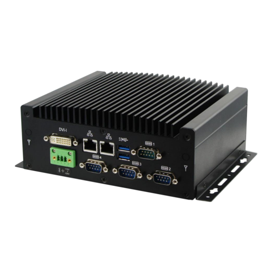
ASB200-908 User Manual CHAPTER 1 INTRODUCTION 1.1 General Description ® ASB200-908 Embedded Box PC comes with 4th Gen. Intel Core i7/i5/i3 Celeron Quad Core/Dual Core processors and Intel HD Integrated Graphics Engine with high performance and low power. It supports DVI-I display output, 2 x USB 3.0, 2 x USB 2.0, 1x CFAST expansion slot, and 2 x Gigabit LAN giving a great selection... - Page 9 1 x USB 3.0 Stacking Connector (2-ports) 2 x RJ-45 GbE Connector 1 x DVI-I Power Adaptor [optional] DPS-60PBA-A00 60W Adapter Input Voltage: 90~264V Input Frequency: 47~63Hz Output Voltage: 12V/5A Desktop or wall mount Mounting Copyright © 2014 IBASE Technology Inc. All Rights Reserved.
- Page 10 ASB200-908 User Manual VESA Mounting VESA mount kit for optional Chassis Material SPCC for EMI enhancement Chassis Color Black 180 (W) x ~150 (D) x 60 (H) mm External dimensions Operating Temperature 0°C~45°C (14°F~113°F) -20°C~80°C (-4°F~176°F) Storage Temperature Relative Humidity 5%~90%@45°C (non-condensing)
-
Page 11: Dimensions
IBASE Technology Inc. 1.2.2 Dimensions Copyright © 2014 IBASE Technology Inc. All Rights Reserved. -
Page 12: I/O View
ASB200-908 User Manual 1.2.3 I/O View Item Connector Item Connector DVI-I 1x RS232 12V~24V DC in 2x Gigabit LAN 2x RS232 for optional 2x USB3.0 1x RS232/422/485... -
Page 13: Exploded View Of The Asb200-908 Assembly
Part No. Description Part No. Description ASB200-908 Heatsink DIP PCBA, IB908 DIP PCBA, ID112 DIP PCBA, IBCFAST BASE ASB200-908_Front 2.5” HDD COM Port Power input connector Power button Sticker_12V~24V CFAST Cover ASB200-908_Bracket Copyright © 2014 IBASE Technology Inc. All Rights Reserved. -
Page 14: Packing List
ASB200-908 User Manual 1.4 Packing List Item No. Description Driver CD User manual Wall mount kit 1.4.1 Optional Items WiFi Solution Description WIRELESS;PCI-E MINI CARD 802.11B/G/N WiFi module [AW-NE238H] (A008WLAWNE238H000P) External Antenna WiFi Antenna (A055RFA02C2M20800P) From Wifi module to Rear/Front panel... -
Page 15: Chapter 2 Motherboard Introduction
U-series processor integrated Memory memory controller - DDR3L (1.35V) @1600 MHz , SO-DIMM [204-pin vertical type] x 2 - Max. 16GB , Non-ECC ® Display Intel Gen. Core i U-series processor integrated Gfx, Copyright © 2014 IBASE Technology Inc. All Rights Reserved. - Page 16 ASB200-908 User Manual supports 3 independent displays, Direct X 11.1, OpenGL 3.2, Open CL 1.2 - DVI-I x 1 (Thru DDI#1 w/ Level shifter [ASM1442K] for DVI + DP to VGA [NXP PTN3392] ) LVDS - LVDS(Thru eDP, via NXP PTN3460 bridge IC) 24-bit dual channels LVDS interface w/DF20 socket x2 ®...
-
Page 17: Board Dimensions
Yes (256 segments, 0, 1, 2…255 sec/min) Watchdog Timer Power Input +12V ~ +24V DC-in RoHS 102mm x 147mm Board Size Windows 8 / Embedded ; Windows 7 / Embedded OS supporting Linux 2.2 Board Dimensions Copyright © 2014 IBASE Technology Inc. All Rights Reserved. -
Page 18: Setting The Jumpers
ASB200-908 User Manual 2.3 Setting the Jumpers Jumpers are used on IB908F to select various settings and features according to your needs and applications. Contact your supplier if you have doubts about the best configuration for your needs. The following lists the connectors on IB908F and their respective functions. - Page 19 J3: Clear CMOS Contents Setting Function Pin 1-2 Short/Close Normal Pin 2-3 Clear Short/Close CMOS J4: Clear ME Contents Setting Function Pin 1-2 Short/Close Normal Pin 2-3 Clear ME Short/Close REGISTER Copyright © 2014 IBASE Technology Inc. All Rights Reserved.
- Page 20 ASB200-908 User Manual J7: Flash Descriptor Security Override (Factory use only) Flash Descriptor Security Override Open Disabled (Default) Close Enabled J9: LVDS Panel Power Selection Setting Panel Voltage 3.3V (default) Pin 1-2 Short/Close Pin 2-3 Short/Close...
- Page 21 IBASE Technology Inc. Connector Locations on IB908F Copyright © 2014 IBASE Technology Inc. All Rights Reserved.
- Page 22 ASB200-908 User Manual CN3, CN4: Gigabit LAN CN3: Intel® Clarkville I218V/I218LM GbE PHY CN4: Intel® Pearsonville I211AT as 2nd GbE CN5: USB 1/2 Connector CN6: VGA DVI-I Connector CN7: DB9 Connector (COM1) is a DB-9 connector. Signal Name Signal Name...
- Page 23 IBASE Technology Inc. Pin # Signal Name RS-232 R2-422 RS-485 DATA- DATA+ Ground Ground Ground Copyright © 2014 IBASE Technology Inc. All Rights Reserved.
- Page 24 ASB200-908 User Manual CN1, CN2: SATA Connectors JP1: LCD Backlight Connector Pin # Signal Name +12V Backlight Enable Brightness Control Ground JP2: USB3/4 Connector Signal Signal Name Name Ground Ground...
- Page 25 The LVDS connectors (Hirose DF20G-20DP-1V) on board consist of the first channel (LVDS1) and second channel (LVDS2). Signal Signal Name Name TX0N TX0P Ground Ground TX1N TX1P Ground Ground TX2N TX2P Ground Ground CLKN CLKP Ground Ground TX3N TX3P Power Power Copyright © 2014 IBASE Technology Inc. All Rights Reserved.
- Page 26 ASB200-908 User Manual JP4: SPI Flash Connector (factory use only) J5: Amplifier Connector Pin # Signal Name OUTL+ OUTL- OUTR- OUTR+ J6, J8: DDR3L SO-DIMM Sockets J7: Factory use only...
- Page 27 IBASE Technology Inc. JP6: SATA HDD Power Connectors Pin # Signal Name Ground Ground +12V JP7: Debug 80 Port Connector (factory use only) J11: MCU Flash Connector (factory use only) Copyright © 2014 IBASE Technology Inc. All Rights Reserved.
- Page 28 ASB200-908 User Manual J12: Smart Battery Pin # Signal Name RST# ICHSWI# Ground SMB_DATA SMB_CLK J13: Board Input Power Connector Pin # Signal Name +9V to +24V...
- Page 29 When pressed again, it will force the system to power off. Power LED: Pins 3 and 4 Pin # Signal Name LED(+) LED(-) Copyright © 2014 IBASE Technology Inc. All Rights Reserved.
- Page 30 ASB200-908 User Manual Hard Disk Drive LED Connector: Pins 5 and 6 This connector connects to the hard drive activity LED on control panel. This LED will flash when the HDD is being accessed. Pin # Signal Name LED(+) LED(-)
- Page 31 RTS, Request to send CTS, Clear to send RI, Ring indicator Not Used J19: Digital I/O Connector Signal Signal Name Name OUT3 OUT1 OUT2 OUT0 CPU_FAN1: CPU Fan Power Connector Copyright © 2014 IBASE Technology Inc. All Rights Reserved.
- Page 32 ASB200-908 User Manual Pin # Signal Name Ground +12V Rotation detection Control...
-
Page 33: Chapter 3 Bios Setup
AMI and your system manufacturer to provide the absolute maximum performance and reliability. Changing the defaults could cause the system to become unstable and crash in some cases. Copyright © 2014 IBASE Technology Inc. All Rights Reserved. - Page 34 ASB200-908 User Manual Main Settings Aptio Setup Utility – Copyright © 2011 American Megatrends, Inc. Main Advanced Chipset Boot Security Save & Exit BIOS Information Choose the system default language Total memory 8176 MB (DDR3) Memory Frequency 1600 Mhz → ←...
- Page 35 F1: General Help ► Shutdown Temperature Configuration F2: Previous Values ► ISmart Controller F3: Optimized Default ► USB Configuration F4: Save ► NCT6102D Super IO Configuration ESC: Exit ► NCT6102D H/W Monitor Copyright © 2014 IBASE Technology Inc. All Rights Reserved.
- Page 36 ASB200-908 User Manual PCI Subsystem Settings Aptio Setup Utility Advanced Main Chipset Boot Security Save & Exit PCI Bus Driver Version V 2.0502 → ← Select Screen ↑↓ Select Item Enter: Select PCI Common Settings Change Field PCI Latency Timer...
- Page 37 Set Maximum Payload of PCI Express Device or allow System BIOS to select the value. Maximum Read Request Set Maximum Read Request Size of PCI Express Device or allow System BIOS to select the value. Copyright © 2014 IBASE Technology Inc. All Rights Reserved.
- Page 38 ASB200-908 User Manual ASPM Support Set the ASPM Level: Force L0s – Force all links to L0s State: AUTO – BIOS auto configure: DISABLE – Disables ASPM. Extended Synch If ENABLED allows generation of Extended Synchronization patterns. Link Training Retry Defines number of Retry Attempts software will take to retrain the link if previous training attempt was unsuccessful.
- Page 39 ↑↓ Select Item Enter: Select Change Field F1: General Help F2: Previous Values F3: Optimized Default F4: Save ESC: Exit Wake on PCIE PME Wake Event The options are Disabled and Enabled. Copyright © 2014 IBASE Technology Inc. All Rights Reserved.
- Page 40 ASB200-908 User Manual CPU Configuration Aptio Setup Utility Advanced Main Chipset Boot Security Save & Exit CPU Configuration Intel(R) CPU Core(TM)i3-4010U @ 1.70GHz CPU Signature 40651 Processor Family Microcode Patch FSB Speed 100MHz Max CPU Speed 1700 MHz Min CPU Speed...
- Page 41 When enabled, a VMM can utilize the additional hardware capabilities provided by Vanderpool Technology. CPU AES Enabled/Disabled CPU Advanced Encryption Standard instructions EIST Enabled/Disabled Intel Speedstep. SATA Configuration SATA Devices Configuration. Copyright © 2014 IBASE Technology Inc. All Rights Reserved.
- Page 42 ASB200-908 User Manual Aptio Setup Utility Advanced Main Chipset Boot Security Save & Exit SATA Controller(s) Enabled SATA Mode Selection AHCI SATA Port0 Empty Software Preserve Unknown Hot Plug Disabled SATA Port1 Empty Software Preserve Unknown Hot Plug Disabled → ←...
- Page 43 Schedule Slot 2 None F3: Optimized Default F4: Save ESC: Exit ISmart Controller Setup the power on time for the system. Schedule Slot 1 / 2 Setup the hour/minute for system power on. Copyright © 2014 IBASE Technology Inc. All Rights Reserved.
- Page 44 ASB200-908 User Manual AMT Configuration Aptio Setup Utility Main Advanced Chipset Boot Security Save & Exit Intel AMT Enabled BIOS Hotkey Pressed Disabled MEBx Selection Screen Disabled Hide Un-Configure ME Confirmation Disabled Un-Configure ME Disabled Amt Wait Timer Activate Remote Assistance Process Disabled →...
- Page 45 Enabled/Disabled. This is a workaround for OSes without EHCI hand-off support. The EHCI ownership change should be claimed by EHCI driver. USB Transfer time-out The time-out value for Control, Bulk, and Interrupt transfers. Copyright © 2014 IBASE Technology Inc. All Rights Reserved.
- Page 46 ASB200-908 User Manual Device reset time-out USB mass Storage device start Unit command time-out. Device power-up delay Maximum time the device will take before it properly reports itself to the Host Controller. ‘Auto’ uses default value: for a Root port it is 100ms, for a Hub port the delay is taken from Hub descriptor.
- Page 47 Advanced Main Chipset Boot Security Save & Exit ► PCH-IO Configuration ► System Agent (SA) Configuration PCH-IO Configuration This section allows you to configure the North Bridge Chipset. Aptio Setup Utility Copyright © 2014 IBASE Technology Inc. All Rights Reserved.
- Page 48 ASB200-908 User Manual Chipset Main Advanced Boot Security Save & Exit Intel PCH RC Version 1.6.2.0 Intel PCH SKU Name Premium SKU Intel PCH Rev ID 03/B1 ► PCI Express Configuration ► USB Configuration ► PCH Azalia Configuration PCH LAN Controller Enabled →...
- Page 49 The control of Active State Power Management on both NB side and SB side of the DMI link. PCIe-USB Glitch W/A PCIe-USB Glitch W/A for bad USB device(s) connected behind PCIE/PEG port. Copyright © 2014 IBASE Technology Inc. All Rights Reserved.
- Page 50 ASB200-908 User Manual USB Configuration Chipset Main Advanced Boot Security Save & Exit USB Configuration → ← USB Precondition Disabled Select Screen xHCI Mode Auto ↑↓ Select Item xHCI Idle L1 Enabled Enter: Select Change Field USB Ports Per-Port Disable Control...
- Page 51 Enabled = Azalia will be unconditionally be enabled. Auto = Azalia will be enabled if present, disabled otherwise. Azalia PME Enable or disable power management capability of the audio controller. System Agent (SA) Configuration Copyright © 2014 IBASE Technology Inc. All Rights Reserved.
- Page 52 ASB200-908 User Manual Aptio Setup Utility Chipset Main Advanced Boot Security Save & Exit System Agent Bridge Name Haswell System Agent RC Version 1.6.2.0 VT-d Capability Supported → ← Select Screen VT-d Enabled ↑↓ Select Item Enter: Select Change Field F1: General Help ►...
- Page 53 Select the Video Device that will be activated during POST. This has no effect if external graphics present. Secondary booty display selection will appear based on your selection. VGA modes will be supported only on primary display. LCD Control Aptio Setup Utility Copyright © 2014 IBASE Technology Inc. All Rights Reserved.
- Page 54 ASB200-908 User Manual Chipset Main Advanced Boot Security Save & Exit → ← Select Screen LCD Control ↑↓ Select Item Primary IGFX Boot Display VBIOS Default Enter: Select LCD Panel Type 1024x768 LVDS Change Field DC Output level LEVEL4 F1: General Help...
- Page 55 F3: Optimized Default F4: Save ESC: Exit Setup Prompt Timeout Number of seconds to wait for setup activation key. 65535(0xFFFF) means indefinite waiting. Bootup NumLock State Select the keyboard NumLock state. Copyright © 2014 IBASE Technology Inc. All Rights Reserved.
- Page 56 ASB200-908 User Manual Quiet Boot Enables/Disables Quiet Boot option. Fast Boot Enables/Disables boot with initialization of a minimal set of devices required to launch active boot option. Has no effect for BBS boot options. Boot Option Priorities Sets the system boot order.
- Page 57 Launch Video OpROM policy Controls the execution of UEFI and Legacy Video OpROM. Other PCI device ROM priority For PCI devices other than Network, Mass storage or Video defines which OpROM to launch. Copyright © 2014 IBASE Technology Inc. All Rights Reserved.
- Page 58 ASB200-908 User Manual Security Settings This section allows you to configure and improve your system and allows you to set up some system features according to your preference. Aptio Setup Utility Security Main Advanced Chipset Boot Save & Exit Password Description If ONLY the Administrator’s password is set, then...
- Page 59 Reset the system after saving the changes. Discard Changes and Reset Reset system setup without saving any changes. Save Changes Save Changes done so far to any of the setup options. Copyright © 2014 IBASE Technology Inc. All Rights Reserved.
- Page 60 ASB200-908 User Manual Discard Changes Discard Changes done so far to any of the setup options. Restore Defaults Restore/Load Defaults values for all the setup options. Save as User Defaults Save the changes done so far as User Defaults. Restore User Defaults...
-
Page 61: Chapter 4 Drivers Installation
INF support for Intel chipset components. Follow the instructions below to complete the installation. 1. Insert the DVD that comes with the board. Click Intel and then Intel(R) 8 Series Chipset Drivers. 2. Click Intel(R) Chipset Software Installation Utility. Copyright © 2014 IBASE Technology Inc. All Rights Reserved. - Page 62 ASB200-908 User Manual 3. When the Welcome screen to the Intel® Chipset Device Software appears, click Next to continue. 4. Click Yes to accept the software license agreement and proceed with the installation process.
- Page 63 5. On the Readme File Information screen, click Next to continue the installation. 6. The Setup process is now complete. Click Finish to restart the computer and for changes to take effect. Copyright © 2014 IBASE Technology Inc. All Rights Reserved.
-
Page 64: Vga Drivers Installation
ASB200-908 User Manual 4.2 VGA Drivers Installation 1. Insert the DVD that comes with the board. Click Intel and then Intel(R) 8 Series Chipset Drivers. 2. Click Intel(R) Core(TM) i3/i5/i7 Graphics Driver. - Page 65 IBASE Technology Inc. 3. When the Welcome screen appears, click Next to continue. 4. Click Yes to to agree with the license agreement and continue the installation. Copyright © 2014 IBASE Technology Inc. All Rights Reserved.
- Page 66 ASB200-908 User Manual 5. On the screen shown below, click Install to continue. 6. Setup complete. Click Finish to restart the computer and for changes to take effect.
-
Page 67: Realtek Hd Audio Driver Installation
4.3 Realtek HD Audio Driver Installation 1. Insert the DVD that comes with the board. Click Intel and then Intel(R) 8 Series Chipset Drivers. 2. Click Realtek High Definition Audio Driver. Copyright © 2014 IBASE Technology Inc. All Rights Reserved. - Page 68 ASB200-908 User Manual 3. On the Welcome to the InstallShield Wizard screen, click Yes to proceed with and complete the installation process. 4. The InstallShield Wizard Complete. Click Finish to restart the computer and for changes to take effect.
-
Page 69: Lan Driver Installation
IBASE Technology Inc. 4.4 LAN Driver Installation 1. Insert the DVD that comes with the board. Click Intel and then Intel(R) 8 Series Chipset Drivers. 2. Click Intel(R) PRO LAN Network Driver. Copyright © 2014 IBASE Technology Inc. All Rights Reserved. - Page 70 ASB200-908 User Manual 3. Click Install Drivers and Software. 4. When the Welcome screen appears, click Next.
- Page 71 IBASE Technology Inc. 5. Click Next to to agree with the license agreement. 6. Click the checkbox for Drivers in the Setup Options screen to select it and click Next to continue. Copyright © 2014 IBASE Technology Inc. All Rights Reserved.
- Page 72 ASB200-908 User Manual 7. The wizard is ready to begin installation. Click Install to begin the installation. 8. When InstallShield Wizard is complete, click Finish.
- Page 73 IBASE Technology Inc. Intel® Management Engine Interface 1. Insert the DVD that comes with the board. Click Intel and then Intel(R) 8 Series Chipset Drivers and then Intel(R) AMT 9.5 Drivers. Copyright © 2014 IBASE Technology Inc. All Rights Reserved.
- Page 74 ASB200-908 User Manual 2. When the Welcome screen to the InstallShield Wizard for Intel® Management Engine Components, click the checkbox for Install Intel® Control Center & click Next. 3. Click Yes to to agree with the license agreement.
- Page 75 IBASE Technology Inc. 4. When the Setup Progress screen appears, click Next. Then, click Finish when the setup progress has been successfully installed. Copyright © 2014 IBASE Technology Inc. All Rights Reserved.
- Page 76 ASB200-908 User Manual Intel® USB 3.0 Drivers 1. Insert the DVD that comes with the board. Click Intel and then Intel(R) 8 Series Chipset Drivers. 2. Click Intel(R) USB 3.0 Drivers.
- Page 77 3. When the Welcome screen to the InstallShield Wizard for Intel® USB 3.0 eXtensible Host Controller Driver, click Next. 4. Click Yes to to agree with the license agreement and continue the installation. Copyright © 2014 IBASE Technology Inc. All Rights Reserved.
- Page 78 ASB200-908 User Manual 5. On the Readme File Information screen, click Next to continue the installation of the Intel® USB 3.0 eXtensible Host Controller Driver. 6. Setup complete. Click Finish to restart the computer and for changes to take effect.
-
Page 79: Appendix
Appendix Mounting ASB200-908 to the Wall You can install ASB200-908 on plastic (LCD monitor), wood, drywall surface over studs, or a solid concrete or metal plane directly. Ensure the installer uses at least four M3 length 6mm screws to secure the system on wall. Four M3 length 6mm screws [Four M3 length 4.4mm for VESA mounting] are recommended to... -
Page 80: Wall Mounting Requirements
ASB200-908 User Manual VESA Mounting [Optional item] Wall Mounting Requirements Note: Before mounting the system on wall, ensure that you are following all applicable building and electric codes. When mounting, ensure that you have enough room for power and signal cable routing. -
Page 81: Selecting The Location
This recommendation reduces the risk that someone may accidentally walk into and damage the device. Local laws governing the safety of individuals might require this type of consideration. Copyright © 2014 IBASE Technology Inc. All Rights Reserved.
Need help?
Do you have a question about the ASB200-908 and is the answer not in the manual?
Questions and answers