
Subscribe to Our Youtube Channel
Related Manuals for IBASE Technology AGS103T


Summary of Contents for IBASE Technology AGS103T
- Page 1 AGS103T Advanced Gateway & Ultra-Compact Fanless System User’s Manual Version 1.0 (September 2021)
- Page 2 No part of this publication may be reproduced, copied, stored in a retrieval system, translated into any language or transmitted in any form or by any means, electronic, mechanical, photocopying, or otherwise, without the prior written consent of IBASE Technology, Inc. (hereinafter referred to as “IBASE”).
- Page 3 0.1% by weight (1000 ppm) except for cadmium, limited to 0.01% by weight (100 ppm). • Lead (Pb) • Mercury (Hg) • Cadmium (Cd) • Hexavalent chromium (Cr6+) • Polybrominated biphenyls (PBB) • Polybrominated diphenyl ether (PBDE) AGS103T User Manual...
- Page 4 You are not suggested to disassemble, repair or make any modification to the device. Disassembly, modification, or any attempt at repair could generate hazards and cause damage to the device, even bodily injury or property damage, and will void any warranty. AGS103T User Manual...
- Page 5 Software in use (such as OS and application software, including the version numbers) 3. If repair service is required, you can download the RMA form at http://www.ibase.com.tw/english/Supports/RMAService/. Fill out the form and contact your distributor or sales representative. AGS103T User Manual...
-
Page 6: Table Of Contents
Introduction ....................2 Features ....................2 Packing List ..................... 3 Optional Accessories ................3 Specifications ................... 4 Product View – AGS103T ................ 6 Dimensions –AGS103T ................9 Dimensions –AGS103TS ................. 9 Chapter 2 Hardware Configuration ............10 Installations .................... 11 2.1.1... - Page 7 Advanced Settings ................. 47 Chipset Settings ..................59 Security Settings ..................61 Boot Settings..................65 Save & Exit Settings................66 Appendix ....................... 67 I/O Port Address Map ................68 Interrupt Request Lines (IRQ) ..............70 Watchdog Timer Configuration ............... 71 AGS103T User Manual...
-
Page 9: Chapter 1 General Information
Chapter 1 General Information The information provided in this chapter includes: • Features • Packing List • Optional Accessories • Specifications • Product View • Dimensions... -
Page 10: Introduction
1.1 Introduction The AGS103T embedded computer is an ultra-compact fanless system AGS103T integrating the Intel Atom® x6000E Series processors (code-named Elkhart Lake) that deliver up to 4 cores with 40% increase in CPU performance and improved graphics when compared with previous versions. Based on the... -
Page 11: Packing List
Your product package should include the items listed below. If any of the items below is missing, contact the distributor or the dealer from whom you purchased the product. • AGS103T / AGS103TS • Wall Mount Kit • Round Head Screw (for Wall Mount Kit) •... -
Page 12: Specifications
Desktop mount / Wall mount (wall mount kit included) • DIN rail mount Dimensions 190 x 52 x 110 mm 190 x 68 x 110 mm (W x H x D) Weight 1.1 kg 1.25 kg Certificate CE / LVD / FCC Class B (pre-scan) AGS103T User Manual... - Page 13 Non-operating: 3 Grms / 5 ~ 500Hz (Random operation) Shock With MIL-STD-810G • Operating: 30 g / 11 ms duration • Non-operating: 40 g / 11 ms duration All specifications are subject to change without prior notice. AGS103T User Manual...
-
Page 14: Product View - Ags103T
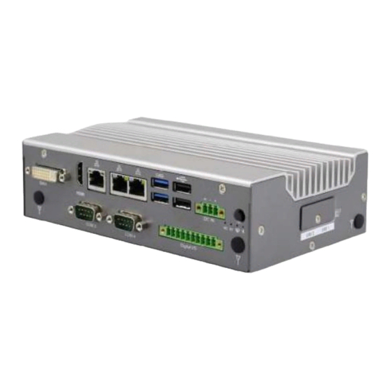
1.6 Product View – AGS103T Front View Name Name CN1: DVI-I Port DC In CN2: HDMI Port DC In Power Input Gigabit LAN Ports Antenna Holes CN5: USB 3.1 Ports COM3/COM4 Ports CN6: USB 2.0 Ports Digital I/O AGS103T User Manual... - Page 15 Remarks: Aside from the antenna hole, the picture above shows the following: CN7:2 in 1 Audio Jack (Line-out/Line-in) CN8:COM1 Connector CN10:COM2 Connector Bottom View Remarks: For AGS103TS, the bottom has a compartment for a 2.5” SSD slot. AGS103T User Manual...
- Page 16 AGS103TS with Wall Mount Brackets AGS103TS with DIN Rail Mount (Optional) AGS103T User Manual...
-
Page 17: Dimensions -Ags103T
General Information –AGS103T 1.7 Dimensions Unit: mm –AGS103TS 1.8 Dimensions Unit: mm AGS103T User Manual... -
Page 18: Chapter 2 Hardware Configuration
Chapter 2 Hardware Configuration The information provided in this chapter includes: • Installations • Information and locations of connectors... -
Page 19: Installations
2. Gently push the module in an upright position until the clips of the slot close to hold the module in place when the module touches the bottom of the slot. To remove the module, press the clips outwards with both hands, and the module will pop-up. AGS103T User Manual... -
Page 20: Mini-Pcie & M.2 Cards Installation / Replacement
1. Thread and fasten the hex nut and the 2. Apply adhesive around here. washer. Then install the antenna. Info: The diameter of the nut is around 6.35 mm (0.25”-36UNC). AGS103T User Manual... -
Page 21: Mounting Installation
2.1.4.1. Wall-Mounting Installation 1. Turn your product upside down to attach the mounting brackets to your product and secure with the supplied 4 screws. 2. Prepare at least 4 screws (M3) to install the device on wall. AGS103T User Manual... -
Page 22: Hdd Module Installation
2. Hook the DIN rail mounting bracket over the top of the DIN rail, and then press the lower section of the bracket towards the DIN rail to clip the bracket onto it. 2.1.5 HDD Module Installation AGS103T User Manual... -
Page 23: Sim Card Installation
1. The SIM card socket design is push-in/push-out type. To install or remove a SIM card, remove the SIM card cover, as shown in the picture below, by releasing the M3 screw. After insertion/removal of the SIM card, replace the SIM card cover and lock it back into place. AGS103T User Manual... -
Page 24: Pinout For Com Ports, Dc-In Power & Line-Out Jack
RS-422 RS-485 DCD, Data carrier detect DATA- RXD, Receive data DATA+ TXD, Transmit data DTR, Data terminal ready RX- Ground Ground Ground DSR, Data set ready RTS, Request to send CTS, Clear to send RI, Ring indicator AGS103T User Manual... - Page 25 DTR, Data terminal ready RX- Ground Ground Ground DSR, Data set ready RTS, Request to send CTS, Clear to send RI, Ring indicator J2 DC-In Power Connector (3-pin terminal block) Assignment Power Ground Case Ground 9V ~ 36V AGS103T User Manual...
- Page 26 Isolated 4-In & 4-Out GPIO Connector (10-pin terminal block) Pin Assignment Pin Assignment Isolation +5V OUT0 OUT1 OUT2 OUT3 Isolation Ground Line-Out / Line-In Jack This connector supports Line-in and Line-out. Line-out supports a 2W speaker. Please see diagram below. AGS103T User Manual...
-
Page 27: Setting The Jumpers
1 2 3 When two pins of a jumper are encased in a jumper cap, this jumper is closed, i.e. turned On. When a jumper cap is removed from two jumper pins, this jumper is open, i.e. turned Off. AGS103T User Manual... -
Page 28: Motherboard Jumper & Connector Locations
2.3 Motherboard Jumper & Connector Locations SL100 Motherboard AGS103T User Manual... - Page 29 Hardware Configuration IP802 Carrier Board AGS103T User Manual...
-
Page 30: Sl100 Motherboard Jumpers And Connectors
2.4 SL100 Motherboard Jumpers and Connectors 2.4.1 SW1: Power Button Switch 2.4.2 RTC RST# (SW2-1) & SRTC RST# (SW2-2) RTC RST# (SW2-1) Function Setting Normal Clear CMOS SRTC RST# (SW2-2) Function Setting Normal Clear ME RTC Register AGS103T User Manual... -
Page 31: Dvi-I Connector (Cn1)
Hardware Configuration 2.4.3 DVI-I Connector (CN1) 2.4.4 HDMI Connector (CN2) 2.4.5 Gigabit LAN RJ45 Connector (CN3) AGS103T User Manual... -
Page 32: Gigabit Lan Rj45 Connectors (Cn4)
2.4.6 Gigabit LAN RJ45 Connectors (CN4) 2.4.7 Dual USB 3.1 Connector (CN5) 2.4.8 Dual USB 2.0 Connector (CN6) AGS103T User Manual... -
Page 33: Line-Out / Line-In Connector (Cn7)
Hardware Configuration 2.4.9 Line-Out / Line-In Connector (CN7) 2.4.10 COM1 Connector (CN8) 2.4.11 SATA Connector (CN9) AGS103T User Manual... -
Page 34: Com2 Connector (Cn10)
2.4.12 COM2 Connector (CN10) 2.4.13 AT/ATX Mode (JP1) Function Pin closed Illustration (default) AGS103T User Manual... -
Page 35: Reset Button Connector (J1)
Hardware Configuration 2.4.14 Reset Button Connector (J1) Pin Assignment Ground Reset BTN 2.4.15 J2: DC-In Power Connector (3-pin terminal block) AGS103T User Manual... -
Page 36: J3: Rtc Battery Connector
2.4.16 J3: RTC Battery Connector 2.4.17 J4: SPI Firmware Header 2.4.18 J5: DDR4 Socket AGS103T User Manual... -
Page 37: J6: Sata Power Connector
Hardware Configuration 2.4.19 J6: SATA Power Connector Pin Assignment 2.4.20 J7: Mini PCIe Socket (Supports USB & SIM1) AGS103T User Manual... -
Page 38: J8: Mini Pcie Socket (Supports Usb, Pcie & Sim2)
2.4.21 J8: Mini PCIe Socket (Supports USB, PCIe & SIM2) 2.4.22 J9(SIM1), J12(SIM2): SIM Socket 2.4.23 J10: Power IC JTAG AGS103T User Manual... -
Page 39: J11:Board-To-Board Connector
Hardware Configuration 2.4.24 J11:Board-to-Board Connector AGS103T User Manual... - Page 40 (COM4) RXD, Receive data (COM4) RI, Ring indicator (COM4) TXD, Transmit data Ground (COM4) DTR, Data terminal ready USB_D+ Ground USB_D- PLT_RST# Ground Ground USB_D+ PCIE_CLK_DP USB_D- PCIE_CLK_DN Ground Ground VCC3_3 PCIE_RXP VCC3_3 PCIE_RXN Ground Ground 3VDUAL PCIE_TXP 3VDUAL PCIE_TXN AGS103T User Manual...
-
Page 41: J13:M.2 B-Key Socket (Supports Sata / Pcie /Usb)
Hardware Configuration 2.4.25 J13:M.2 B-Key Socket (Supports SATA / PCIe /USB) 2.4.26 J14:Port 80 Header 2.4.27 LED1: Power_Fail (Red) 2.4.28 LED2: Heartbeat (Blue) 2.4.29 LED3: WWAN1 (Green) 2.4.30 LED4: WWAN2 (Green) AGS103T User Manual... -
Page 42: Chapter 3 Driver Installation
Chapter 3 Driver Installation The information provided in this chapter includes: • ® Intel Chipset Software Installation Utility • Graphics Driver Installation • HD Audio Driver Installation • ® Intel Management Engine Drivers Installation • LAN Driver Installation... -
Page 43: Introduction
INF files for Plug & Play function for the chipset components. Follow the instructions below to complete the installation. 1. Insert the disk enclosed in the package with the board. Click Intel on the left pane and then Intel(R) Elkhartlake Chipset Drivers on the right pane. AGS103T User Manual... - Page 44 Next to continue. 4. Accept the software license agreement and proceed with the installation process. 5. On the Readme File Information screen, click Install for installation. 6. After the installation, press Finish to complete the setup process. AGS103T User Manual...
-
Page 45: Graphics Driver Installation
1. Insert the disk enclosed in the package with the board. Click Intel on the left pane and then Intel(R) Elkhartlake Chipset Drivers on the right pane. 2. Click Intel(R) Elkhartlake Graphics Driver. 3. When the Welcome screen appears, click Next to continue. AGS103T User Manual... - Page 46 4. Click Yes to accept the license agreement and click Next in The Readme File Information screen. Click Next in the Setup Progress screen. 5. Restart the computer when prompted. Click Finish, then remove any installation media from the drives. AGS103T User Manual...
-
Page 47: Hd Audio Driver Installation
2. Click Realtek High Definition Audio Driver. 3. On the Welcome screen, click Next to continue. 4. When the InstallShield Wizard has successfully installed the Realtek Audio Driver, restart the computer. Click Finish to complete the setup. AGS103T User Manual... -
Page 48: Intel® Me Drivers Installation
1. Insert the disk enclosed in the package with the board. Click Intel on the left pane and then Intel(R) ME Drivers. 2. The welcome screen to the Intel® Management Engine Components appears. Click Next to continue. AGS103T User Manual... - Page 49 Driver Installation 3. Accept the license agreement and click Next. 4. On the Setup’s Destination Folder screen, click Next to continue. 5. After the Intel® components have been completely installed, click Finish. AGS103T User Manual...
-
Page 50: Lan Driver Installation
2. Choose Intel(R) I21x Gigabit Network Drivers. 3. In the welcome screen to the install wizard for Intel(R) Network Connections, click Next. 4. On the next screen, accept the terms in the license agreement and click Next. AGS103T User Manual... - Page 51 Driver Installation 5. In the Setup Options screen, click Next. 6. Click install to begin the installation. 7. Click Finish when Install wizard has completed. AGS103T User Manual...
-
Page 52: Chapter 4 Bios Setup
Chapter 4 BIOS Setup This chapter describes the different settings available in the AMI BIOS that comes with the board. The topics covered in this chapter are as follows: • Main Settings • Advanced Settings • Chipset Settings • Security Settings •... -
Page 53: Introduction
These defaults have been carefully chosen by both AMI and your system manufacturer to provide the absolute maximum performance and reliability. Changing the defaults could make the system unstable and crash in some cases. AGS103T User Manual... -
Page 54: Main Settings
4.3 Main Settings BIOS Setting Description Sets the date. System Date Use the <Tab> key to switch between the data elements. Set the time. System Time Use the <Tab> key to switch between the data elements. AGS103T User Manual... -
Page 55: Advanced Settings
Displays system ACPI parameters. Fintek Super IO Displays super IO chip parameters. Configuration Fintek Hardware Monitor Shows super IO monitor hardware status. USB Configuration Displays USB configuration parameters. Network Stack Enables / Disables UEFI Network Stack. Configuration AGS103T User Manual... - Page 56 4.4.1 CPU Configuration BIOS Setting Description When enabled, a VMM can ultilize the Intel (VMX) Virtualization additional hardware capabilities provided by Technolgy Varderpool Technology. AGS103T User Manual...
- Page 57 BIOS Setup 4.4.2 PCH-FW Configuration BIOS Setting Description When disabled, ME will be put into ME ME State temporarily Disabled Mode. AGS103T User Manual...
- Page 58 • TPM 2.0 will restrict support to TPM 2.0 devices only. • Device Select Auto will support both with the default being set to TPM 2.0 deices if not found, and TPM 1.2 device will be enumerated. AGS103T User Manual...
- Page 59 Enables / Disables the system ability to hibernate Hibernation (OS/S4 Sleep State). This option may be not effective with some OS. Selects an ACPI sleep state (Suspend Disabled or S3) ACPI Sleep where the system will enter when the Suspend button is State pressed. AGS103T User Manual...
- Page 60 BIOS Setting Description Power Failure Options: Always on, Always off Sets parameters of serial ports. Serial Ports Enables / Disables the serial port and select an optimal Configuration setting for the Super IO device. Serial Port 1 Configuration AGS103T User Manual...
- Page 61 BIOS Setup Serial Port 2 Configuration AGS103T User Manual...
- Page 62 Serial Port 3 Configuration AGS103T User Manual...
- Page 63 BIOS Setup Serial Port 4 Configuration AGS103T User Manual...
- Page 64 Fintek Hardware Monitor BIOS Setting Description These fields are the parameters of the hardware monitoring function feature of the Temperatures / Voltages motherboard. The values are read-only as monitored by the system and showing the PC health status AGS103T User Manual...
- Page 65 For a Hub port, the delay is taken from Hub descriptor. Mas storage device emulation type. ‘AUTO’ Generic Ultra enumerates devices according to their media format. Optical drives are emulated as ‘CDROM’ drives with no MS-COMBO media will be emulated according to a drive type AGS103T User Manual...
- Page 66 4.4.8 Network Stack Configuration BIOS Setting Description Network Stack Enables / Disables UEFI Network Stack. AGS103T User Manual...
-
Page 67: Chipset Settings
Keep IGFX enabled based on the setup options GTT Size Options: 2MB, 4MB, 8MB Select the Aperture Size. Note: Above 4GB MMIO BIOS assignment is automatically enabled when Aperture Size selecting 2048MB aperture. To use this feature, please disable CSM Support AGS103T User Manual... - Page 68 Description SATA Controller(s) Enables / Disables the Serial ATA. SATA Mode Determines how SATA controller(s) operate. Selection Serial ATA Port 0~1 Enables / Disables Serial Port 0~1. SATA Ports Hot Enables / Disables SATA Ports HotPlug. Plug AGS103T User Manual...
-
Page 69: Security Settings
BIOS Setup 4.6 Security Settings BIOS Setting Description Setup Administrator Sets an administrator password for the setup Password utility. User Password Sets a user password. Secure Boot Secure Boot Configuration AGS103T User Manual... - Page 70 AGS103T User Manual...
- Page 71 BIOS Setup AGS103T User Manual...
- Page 72 AGS103T User Manual...
-
Page 73: Boot Settings
Turns on/off the keyboard NumLock state. Quiet Boot Enables / Disables Quiet Boot option. Fixed Boot Order Sets the system boot order. Priorities UEFI Hard Disk Drive Specifies the boot device priority sequence from BBS Priorities available UEFI hard disk drives. AGS103T User Manual... -
Page 74: Save & Exit Settings
Restores / Loads defaults values for all the setup Restore Defaults options. Save as User Defaults Saves the changes done so far as user defaults. Restores the user defaults to all the setup Restore User Defaults options. AGS103T User Manual... -
Page 75: Appendix
Appendix This section provides the mapping addresses of peripheral devices and the sample code of watchdog timer configuration. • I/O Port Address Map • Interrupt Request Lines (IRQ) • Watchdog Timer Configuration... -
Page 76: I/O Port Address Map
A. I/O Port Address Map AGS103T User Manual... - Page 77 Appendix AGS103T User Manual...
-
Page 78: Interrupt Request Lines (Irq)
IRQ 4294967280~85 Intel I210 Gigabit Network Connection #6 IRQ 4294967286~91 Intel I210 Gigabit Network Connection #4 IRQ 4294967292 Intel(R) UHD Graphics IRQ 4294967293 Intel(R) USB 3.10 eXtensible Host Controller - 1.20 (Microsoft) IRQ 4294967294 Standard SATA AHCI Controller AGS103T User Manual... -
Page 79: Watchdog Timer Configuration
81866 watch dog program\n"); SIO = Init_F81964(); if (SIO == 0) printf("Can not detect Fintek 81866, program abort.\n"); return(1); }//if (SIO == 0) if (argc != 2) printf(" Parameter incorrect!!\n"); return (1); bTime = strtol (argv[1], endptr, 10); AGS103T User Manual... - Page 80 //--------------------------------------------------------------------------- void DisableWDT(void) unsigned char bBuf; Set_F81964_LD(0x07); //switch to logic device 7 bBuf = Get_F81964_Reg(0xFA); bBuf &= ~0x01; Set_F81964_Reg(0xFA, bBuf); //disable WDTO output bBuf = Get_F81964_Reg(0xF5); bBuf &= ~0x20; bBuf |= 0x40; Set_F81964_Reg(0xF5, bBuf); //disable WDT //--------------------------------------------------------------------------- AGS103T User Manual...
- Page 81 //Fintek 81866 goto Init_Finish; } F81964_BASE = 0x00; result = F81964_BASE; Init_Finish: return (result); //--------------------------------------------------------------------------- void Unlock_F81964 (void) outportb(F81964_INDEX_PORT, F81964_UNLOCK); outportb(F81964_INDEX_PORT, F81964_UNLOCK); //--------------------------------------------------------------------------- void Lock_F81964 (void) outportb(F81964_INDEX_PORT, F81964_LOCK); //--------------------------------------------------------------------------- void Set_F81964_LD( unsigned char LD) Unlock_F81964(); outportb(F81964_INDEX_PORT, F81964_REG_LD); AGS103T User Manual...
- Page 82 #define F81964_DATA_PORT (F81964_BASE+1) //--------------------------------------------------------------------------- #define F81964_REG_LD 0x07 //--------------------------------------------------------------------------- #define F81964_UNLOCK 0x87 #define F81964_LOCK 0xAA //--------------------------------------------------------------------------- unsigned int Init_F81964(void); void Set_F81964_LD( unsigned char); void Set_F81964_Reg( unsigned char, unsigned char); unsigned char Get_F81964_Reg( unsigned char); //--------------------------------------------------------------------------- #endif // F81964_H AGS103T User Manual...
Need help?
Do you have a question about the AGS103T and is the answer not in the manual?
Questions and answers