
Related Manuals for IBASE Technology AGS100T


Summary of Contents for IBASE Technology AGS100T
- Page 1 AGS100/ AGS100T/ AGS102/ AGS102T Advanced Gateway & Ultra-Compact Fanless System User’s Manual Version 1.3 (September 2021)
- Page 2 No part of this publication may be reproduced, copied, stored in a retrieval system, translated into any language or transmitted in any form or by any means, electronic, mechanical, photocopying, or otherwise, without the prior written consent of IBASE Technology, Inc. (hereinafter referred to as “IBASE”).
- Page 3 Compliance This product has passed CE tests for environmental specifications and limits. This product is in accordance with the directives of the Union European (EU). If users modify and/or install other devices in this equipment, the CE conformity declaration may no longer apply. This product has been tested and found to comply with the limits for a Class B device, pursuant to Part 15 of the FCC Rules.
- Page 4 Important Safety Information Carefully read the precautions before using the device. Environmental conditions: Lay the device horizontally on a stable and solid surface in case the device may fall, causing serious damage. Make sure you leave plenty of space around the device for ventilation. ...
- Page 5 CAUTION Replace only with the same or equivalent type recommended by the manufacturer. Dispose of used batteries according to the manufacturer’s instructions. Warranty Policy IBASE standard products: 24-month (2-year) warranty from the date of shipment. If the date of shipment cannot be ascertained, the product serial numbers can be used to determine the approximate shipping date.
-
Page 6: Table Of Contents
Product View – AGS102 ................10 Product View – AGS102T ................ 12 1.10 Dimensions – AGS100 / AGS100T ............14 1.11 Dimensions – AGS102 / AGS102T ............14 Chapter 2 ... - Page 7 Chapter 3 Driver Installation ..............31 Introduction ....................32 Intel ® Chipset Software Installation Utility ..........32 Graphics Driver Installation ..............34 HD Audio Driver Installation ..............36 Intel ® Trusted Execution Engine Driver Installation ......... 37 ...
-
Page 9: Chapter 1 General Information
Chapter 1 General Information The information provided in this chapter includes: Features Packing List Optional Accessories Specifications Product View Dimensions... -
Page 10: Introduction
1.1 Introduction AGS100, AGS102, AGS100T, and AGS102T are embedded computing systems designed for thin clients, smart industrial automation or controller, and ® ® ® retail equipment. It is based on Intel Atom™ / Pentium / Celeron processors and features iSMART that enables auto-scheduling for general applications and energy savings. -
Page 11: Packing List
Your product package should include the items listed below. If any of the items below is missing, contact the distributor or the dealer from whom you purchased the product. AGS100 / AGS102 / AGS100T/ AGS102T Wall Mount Kit ... -
Page 12: Specifications
1.5 Specifications Product Name AGS100 AGS102 AGS100T AGS102T System Motherboard IB801 IB802T Carrier Board IP801 IP801 Operating Windows10 (64-bit) System Linux Ubuntu Intel ® Atom™ E3950 / E3940 / E3930, Pentium ® N4200, Celeron ® N3350 / E3940 Series CPU Speed Up to 2.5 GHz... - Page 13 3 x LED indicators (HDD, WLAN, WWAN) 1 x power button with LED (Green for AGS100 / AGS102, and blue for AGS100T / AGS102T) 1 x 3-pin DC-in terminal block type for 9-36V 1 x Antenna hole for WLAN module ...
-
Page 14: Product View - Ags100
1.6 Product View – AGS100 Front View Side View Name Name Power Button DVI-I Port (Silver for AGS100) LED Indicatorss (Red for HDD, Blue for WLAN, Wall Mount Kit Yellow for WWAN) DC-In Power Connector (3- pin) Antenna Holes Audio Line-Out Jack (supports USB 3.0 Ports 2W mono speaker) COM1 &... - Page 15 General Information Wall Mount DIN Rail Mount (Optional) AGS100/T & AGS102/T User Manual...
-
Page 16: Product View - Ags100T
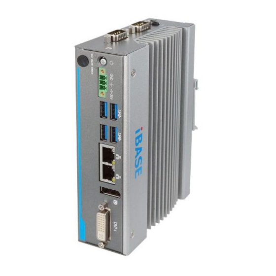
1.7 Product View – AGS100T Front View Side View Name Name Power Button DVI-I Port (Black for AGS100T) LED Indicatorss (Red for HDD, Blue for WLAN, Wall Mount Kit Yellow for WWAN) DC-In Power Connector (3-pin) Antenna Holes Audio Line-Out Jack (supports USB 3.0 Ports... - Page 17 General Information Wall Mount DIN Rail Mount (Optional) AGS100/T & AGS102/T User Manual...
-
Page 18: Product View - Ags102
1.8 Product View – AGS102 Front View Rear View Name Name Power Button GPIO Port (Silver for AGS102) LED Indicatorss (Red for HDD, Blue for WLAN, DVI-I Port Yellow for WWAN) USB 2.0 Port Wall Mount Kit DC-In Power Connector (3-pin) Antenna Holes Audio Line-Out Jack (supports USB 3.0 Ports... - Page 19 General Information Wall Mount DIN Rail Mount (Optional) AGS100/T & AGS102/T User Manual...
-
Page 20: Product View - Ags102T
1.9 Product View – AGS102T Front View Rear View Name Name Power Button GPIO Port (Black for AGS102T) LED Indicatorss (Red for HDD, Blue for WLAN, DVI-I Port Yellow for WWAN) USB 2.0 Port Wall Mount Kit DC-In Power Connector (3-pin) Antenna Holes Audio Line-Out Jack (supports USB 3.0 Ports... - Page 21 General Information Wall Mount DIN Rail Mount (Optional) AGS100/T & AGS102/T User Manual...
-
Page 22: Dimensions - Ags100 / Ags100T
1.10 Dimensions – AGS100 / AGS100T Unit: mm 1.11 Dimensions – AGS102 / AGS102T Unit: mm AGS100/T & AGS102/T User Manual... -
Page 23: Chapter 2 Hardware Configuration
Chapter 2 Hardware Configuration The information provided in this chapter includes: Installations Information and locations of connectors... -
Page 24: Installations
2.1 Installations Turn your product upside down and take away the device bottom cover by removing 6 screws as indicated below for the installation or replacement of the memory module, mSATA SSD or WLAN card. After installations, secure the device bottom cover back. 2.1.1 Memory Installation / Replacement If you need to install or replace a memory module, follow the instructions below... -
Page 25: Mini-Pcie & M.2 Cards Installation / Replacement
Hardware Configuration 2.1.2 Mini-PCIe & M.2 Cards Installation / Replacement After removing the bottom cover, follow the instructions below. 1. Locate the mini-PCIe or M.2 slot, align the key of the card to the interface, and insert the card slantwise. Mini-PCIe card: M.2 card: 2. -
Page 26: Mounting Installation
2.1.4 Mounting Installation Requirements Before mounting the system, ensure that you have enough room for power and signal cable routing, and have good ventilation for the power adaptor. The method of mounting must be able to support the weight of the device plus the weight of the suspending cables to be attached to the system. - Page 27 Hardware Configuration 2.1.4.2. DIN Rail Mounting Installation (Optional) 1. Attach the DIN rail mounting bracket to your product, and secure with the supplied 2 screws. 2. Hook the DIN rail mounting bracket over the top of the DIN rail, and then press the lower section of the bracket towards the DIN rail to clip the bracket onto it.
-
Page 28: Pinout For Com Ports, Dc-In Power Connector & Line-Out Jack
2.1.5 Pinout for COM Ports, DC-In Power Connector & Line-Out Jack 2.1.5.1. COM1 & COM2 RS232/422/485 Ports COM1 and COM2 ports are jumper-less and configurable in BIOS. Assignment RS-232 RS-422 RS-485 DCD, Data carrier detect DATA- RXD, Receive data DATA+ TXD, Transmit data DTR, Data terminal ready... - Page 29 Hardware Configuration 2.1.5.2. COM3 & COM4 Port (for AGS102 & AGS102T only) COM3 and COM4 are both available for AGS102 / AGS102T only. RS-232 for AGS102: Pin Assignment Assignment DCD, Data carrier detect DSR, Data set ready RXD, Receive data RTS, Request to send TXD, Transmit data CTS, Clear to send...
- Page 30 2.1.5.4. Isolated 4-In & 4-Out GPIO Connector (10-pin terminal block) Assignment Assignment Isolation +5V OUT0 OUT1 OUT2 OUT3 Isolation Ground 2.1.5.5. Audio Line-Out Jack for AGS100(T) & AGS102(T) AGS100 AGS102 support 2W mono speaker. Please see diagram below. (AGS100T AGS102T support stereo output.) AGS100/T & AGS102/T User Manual...
-
Page 31: Setting The Jumpers
Hardware Configuration 2.2 Setting the Jumpers Set up and configure your device by using jumpers for various settings and features according to your needs and applications. Contact your supplier if you have doubts about the best configuration for your use. 2.2.1 How to Set Jumpers Jumpers are short-length conductors consisting of several metal pins with a... -
Page 32: Motherboard Jumper & Connector Locations
2.3 Motherboard Jumper & Connector Locations Motherboard: IB801 / IB802T AGS100/T & AGS102/T User Manual... - Page 33 Hardware Configuration Bottom AGS100/T & AGS102/T User Manual...
-
Page 34: Motherboard Jumpers Quick Reference
2.4 Motherboard Jumpers Quick Reference Function Connector Name Page Clear ME Register Clear CMOS Data Factory Use Only JP4, 2.4.1 Clear ME Register (JP1) Function Pin closed Illustration Normal (default) Clear ME Register 2.4.2 Clear CMOS Data (JP2) Function Pin closed Illustration Normal (default) -
Page 35: Motherboard Connectors Quick Reference
Hardware Configuration 2.5 Motherboard Connectors Quick Reference Motherboard: IB801 / IB802T Function Connector Page Battery Connector BAT1 Reset Button Connector Power Button Connector Board-to-Board Connector Power Button USB 3.0 Port CN1, CN2 Dual GbE LAN Port DisplayPort DVI-I Port Audio Line-Out Jack Nano SIM Card Slot COM1 &... -
Page 36: Battery Connector (Bat1)
2.5.1 Battery Connector (BAT1) Pin Assignment Pin Assignment Battery+ Ground 2.5.2 Reset Button Connector (J1) Pin Assignment Pin Assignment Ground Reset BTN 2.5.3 Power Button Connector (J3) Pin Assignment Pin Assignment Ground Power BTN AGS100/T & AGS102/T User Manual... -
Page 37: Board-To-Board Connector (J11)
Hardware Configuration 2.5.4 Board-to-Board Connector (J11) (Male) Pin Assignment Assignment Ground VCC5 GPIO_IN0 VCC5 GPIO_IN1 GPIO_OUT0 GPIO_IN3 GPIO_OUT1 GPIO_IN4 GPIO_OUT2 (COM3) DSR, Data set ready GPIO_OUT3 (COM3) RTS, Request to (COM3) DCD, Data carrier send detect (COM3) CTS, Clear to send (COM3) RXD, Receive data (COM3) RI, Ring indicator (COM3) TXD, Transmit data... -
Page 38: Carrier Board Connectors Quick Reference (For Ags102 / Ags102T Only)
2.6 Carrier Board Connectors Quick Reference (for AGS102 / AGS102T only) Carrier Board: IP801 IP801 - Top Function Connector COM3 & COM4 Port CN2 (COM3), CN3 (COM4) Isolated 4-In & 4-Out GPIO Connector Board-to-Board Connector USB 2.0 Port [1]: Refer to 2.1.5.2 COM3 & COM4 Port (for AGS102 &... -
Page 39: Chapter 3 Driver Installation
Chapter 3 Driver Installation The information provided in this chapter includes: Intel ® Chipset Software Installation Utility Graphics Driver Installation HD Audio Driver Installation Intel Trusted Execution Engine Drivers Installation ® Intel ® Serial I/O Drivers ... -
Page 40: Introduction
3.1 Introduction This section describes the installation procedures for software drivers. The software drivers are in a disk enclosed with the product package. If you find anything missing, please contact the distributor where you made the purchase. Note: After installing your Windows operating system, you must install the ®... - Page 41 Driver Installation ® 3. When the Welcome screen to the Intel Chipset Device Software appears, click Next. 4. Accept the software license agreement to continue. 5. On the Readme File Information screen, click Install and then Next. 6. When the driver is completely installed, click Finish and restart the computer for changes to take effect.
-
Page 42: Graphics Driver Installation
3.3 Graphics Driver Installation 1. Click Intel and then Intel(R) Apollolake Chipset Drivers. 2. Click Intel(R) Apollolake Graphics Driver. 3. When the Welcome screen appears, click Next to continue. AGS100/T & AGS102/T User Manual... - Page 43 Driver Installation 4. Click Yes to agree with the license agreement and continue the installation. 5. Read the Readme File Information and then click Next until the installation starts. 6. Choose a destination folder for installation. 7. When the driver is completely installed, click Finish and restart the computer for changes to take effect.
-
Page 44: Hd Audio Driver Installation
3.4 HD Audio Driver Installation 1. Insert the disk enclosed in the package. Click Intel and then Intel(R) Apollolake Chipset Drivers. 2. Click Realtek High Definition Audio Driver. 3. On the Welcome screen of the InstallShield Wizard, click Next until the installation starts. -
Page 45: Intel Trusted Execution Engine Driver Installation
Driver Installation ® 3.5 Intel Trusted Execution Engine Driver Installation 1. Click Intel and then Intel(R) Apollolake Chipset Drivers. 2. Click Intel(R) TXE Drivers. 3. When the Welcome screen appears, click Next to continue. 4. Accept the licence agreement and click Next to continue. 5. -
Page 46: Usb 3.1 Driver Installation
3.6 USB 3.1 Driver Installation 1. Click Intel and then Intel(R) Apollolake Chipset Drivers. 2. Click Intel(R) Serial IO Drivers. 3. When the Welcome screen appears, click Next to continue. 4. When the driver is completely installed, click Finish and restart the computer for changes to take effect. -
Page 47: Lan Driver Installation
Driver Installation 3.7 LAN Driver Installation 1. Click LAN Card on the left and then Intel(R) I21x Giagabit Network Drivers 2. When the Welcome screen appears, click Next to continue. 3. Tick the checkboxes to select the related drivers and click Next. AGS100/T &... - Page 48 4. When the wizard is ready for installation, click Install. 5. When the driver is completely installed, click Finish and restart the computer for changes to take effect. AGS100/T & AGS102/T User Manual...
-
Page 49: Chapter 4 Bios Setup
Chapter 4 BIOS Setup This chapter describes the different settings available in the AMI BIOS that comes with the board. The topics covered in this chapter are as follows: Main Settings Advanced Settings Chipset Settings Security Settings ... -
Page 50: Introduction
4.1 Introduction The BIOS (Basic Input/Output System) installed in the ROM of your computer system supports Intel® processors. The BIOS provides critical low-level support for standard devices such as disk drives, serial ports and parallel ports. It also provides password protection as well as special support for detailed fine-tuning of the chipset controlling the entire system. -
Page 51: Main Settings
BIOS Setup 4.3 Main Settings BIOS Setting Description Sets the date. System Date Use the <Tab> key to switch between the data elements. Set the time. System Time Use the <Tab> key to switch between the data elements. AGS100/T & AGS102/T User Manual... -
Page 52: Advanced Settings
4.4 Advanced Settings This section allows you to configure, improve your system and allows you to set up some system features according to your preference. BIOS Setting Description ACPI Settings Displays system ACPI parameters. iSmart Controller Sets up schedules for power management. Fintek Super IO Displays super IO chip parameters. - Page 53 BIOS Setup 4.4.1 ACPI Settings BIOS Setting Description Enables / Disables the system ability to Enable Hibernation hibernate (OS/S4 Sleep State). This option may not be effective with some OS. Selects a ACPI sleep state for the system to enter. ACPI Sleep State Options: Suspend Disabled, S3 (Suspend to RAM)
- Page 54 4.4.2 iSmart Controller BIOS Setting Description Power-On after Power Enables / Disables the system to be turned on failure automatically after a power failure. Generate the reset signal when system hands Temperature Guardian up on POST. Sets up the hour / minute / day for the power-on schedule for the system.
- Page 55 BIOS Setup 4.4.3 Fintek Super IO Configuration BIOS Setting Description Sets Parameters of Serial Ports. You can enable / disable the serial port and Serial Port Configuration select an optimal settings for the Super IO device. AGS100/T & AGS102/T User Manual...
- Page 56 4.4.3.1. Serial Port 1 Configuration BIOS Setting Description Serial Port Enables / Disables serial port (COM). Selects an optimal settings for Super I/O device. Options: Auto Change Settings IO = 3F8h; IRQ = 4 IO = 3F8h; IRQ = 3, 4, 5, 6, 7, 9, 10, 11, 12 ...
- Page 57 BIOS Setup 4.4.3.2. Serial Port 2 Configuration BIOS Setting Description Serial Port Enables / Disables serial port (COM). Selects an optimal settings for Super I/O device. Options: Auto Change Settings IO = 2F8h; IRQ = 3 IO = 3F8h; IRQ = 3, 4, 5, 6, 7, 9, 10, 11, 12 ...
- Page 58 4.4.3.3. Serial Port 3 Configuration BIOS Setting Description Serial Port Enables / Disables serial port (COM). Selects an optimal settings for Super I/O device. Options: Auto Change Settings IO = 3E8h; IRQ = 7 IO = 3E8h; IRQ = 3, 4, 5, 6, 7, 9, 10, 11, 12 ...
- Page 59 BIOS Setup 4.4.3.4. Serial Port 4 Configuration BIOS Setting Description Serial Port Enables / Disables serial port (COM). Selects an optimal settings for Super I/O device. Options: Auto Change Settings IO = 2E8h; IRQ = 7 IO = 3E8h; IRQ = 3, 4, 5, 6, 7, 9, 10, 11, 12 ...
- Page 60 4.4.4 Fintek Hardware Monitor BIOS Setting Description These fields are the parameters of the hardware monitoring function feature of the Temperatures / Voltages motherboard. The values are read-only as monitored by the system and showing the PC health status This field enables or disables the Shutdown Temperature CPU Shutdown Options: Disabled (default),.
- Page 61 BIOS Setup 4.4.5 CPU Configuration BIOS Setting Description Socket 0 CPU Information Socket specific CPU Information The turbo mode is activable for CPU power CPU Power Management management. Monitor Mwait Enables / Disables Monitor Mwait. 4.4.6 Network Stack Configuration BIOS Setting Description Network Stack Enables / Disables UEFI Network Stack.
- Page 62 4.4.7 CSM Configuration BIOS Setting Description CSM Support Enables / Disables CSM support. The option Upon Request disables GA20 when using BIOS services. GateA20 Active The option Always cannot disable GA20, but is useful when any RT code is executed above 1 MB.
- Page 63 BIOS Setup 4.4.8 USB Configuration BIOS Setting Description Enables / Disables Legacy USB support. Auto disables legacy support if there is no Legacy USB Support USB device connected. Disable keeps USB devices available only for EFI applications. This is a workaround for OSes without XHCI XHCI Hand-pff hand-off support.
-
Page 64: Chipset Settings
4.5 Chipset Settings BIOS Setting Description HD-Audio Configuration HD audio configuration settings PCI Express PCI Express Configuration Settings Configuration Press Enter to select the SATA device SATA Drives configuration setup options. USB Configuration USB configuration settings AGS100/T & AGS102/T User Manual... - Page 65 BIOS Setup 4.5.1 HD-Audio Configuration BIOS Setting Description HD Audio Support Enables / Disables HD audio support. 4.5.2 PCI Express Configuration BIOS Setting Description Enables / Disables the PCI Express root port. PCI Express Root Auto: Disables unused root port automatically Port 1 ~ 6 for the most optimum power savings.
- Page 66 4.5.2.1. PCI Express Root Port 1 ~ 6 BIOS Setting Description Enables / Disables the PCI Express root port. PCI Express Root Auto: Disables unused root port automatically Port 1 ~ 6 for the most optimum power savings. PCI Express active state power management settings.
- Page 67 BIOS Setup 4.5.3 SATA Drives BIOS Setting Description Enables / Disables the Chipset SATA controller. The Chipset SATA controller supports the 2 Chipset SATA black internal SATA ports (up to 3 Gb/s supported per port). SATA Mode Selection Determines how SATA controller(s) operation. Option: AHCI AGS100/T &...
- Page 68 4.5.4 USB Configuration BIOS Setting Description Enables / Disables XHCI pre-boot driver XHCI Pre-Boot Driver support. Once disbled, XHCI controller would be function disabled. None of the USB devices are XHCI Mode detectable and usable during boot and in OS. Do not disable it unless for debug purpose.
-
Page 69: Security Settings
BIOS Setup 4.6 Security Settings BIOS Setting Description Setup Administrator Sets an administrator password for the setup Password utility. User Password Sets a user password. AGS100/T & AGS102/T User Manual... -
Page 70: Boot Settings
4.7 Boot Settings BIOS Setting Description Number of seconds to wait for setup activation key. Setup Prompt Timeout 65535 (0xFFFF) means indefinite waiting. Bootup NumLock State Turns on/off the keyboard NumLock state. Quiet Boot Enables / Disables Quiet Boot option. Controls the placement of newly detected UEFI boot options. -
Page 71: Save & Exit Settings
BIOS Setup 4.8 Save & Exit Settings BIOS Setting Description Save Changes and Exit Exits system setup after saving the changes. Discard Changes and Exit Exits system setup without saving any changes. Save Changes and Reset Resets the system after saving the changes. Discard Changes and Resets system setup without saving any Reset... -
Page 72: Appendix
Appendix This section provides the mapping addresses of peripheral devices and the sample code of watchdog timer configuration. I/O Port Address Map Interrupt Request Lines (IRQ) Watchdog Timer Configuration... -
Page 73: I/O Port Address Map
Appendix A. I/O Port Address Map Each peripheral device in the system is assigned a set of I/O port addresses which also becomes the identity of the device. The following table lists the I/O port addresses used. Address Device Description 0x0000F090-0x0000F097 Standard SATA AHCI Controller 0x0000F080-0x0000F083... - Page 74 Address Device Description 0x00000028-0x00000029 Programmable interrupt controller 0x0000002C-0x0000002D Programmable interrupt controller 0x00000030-0x00000031 Programmable interrupt controller 0x00000034-0x00000035 Programmable interrupt controller 0x00000038-0x00000039 Programmable interrupt controller 0x0000003C-0x0000003D Programmable interrupt controller 0x000000A0-0x000000A1 Programmable interrupt controller 0x000000A4-0x000000A5 Programmable interrupt controller 0x000000A8-0x000000A9 Programmable interrupt controller 0x000000AC-0x000000AD Programmable interrupt controller 0x000000B0-0x000000B1 Programmable interrupt controller...
-
Page 75: Interrupt Request Lines (Irq)
Appendix B. Interrupt Request Lines (IRQ) Peripheral devices use interrupt request lines to notify CPU for the service required. The following table shows the IRQ used by the devices on board. Level Function IRQ 4294967294 Standard SATA AHCI Controller IRQ 25 High Definition Audio Controller IRQ 8 High precision event timer... -
Page 76: Watchdog Timer Configuration
C. Watchdog Timer Configuration The Watchdog Timer (WDT) is used to generate a variety of output signals after a user programmable count. The WDT is suitable for the use in the prevention of system lock-up, such as when software becomes trapped in a deadlock. - Page 77 Appendix printf("System will reset after %d seconds\n", bTime); if (bTime) EnableWDT(bTime); } else DisableWDT(); } return 0; //--------------------------------------------------------------------------- void EnableWDT(int interval) unsigned char bBuf; bBuf = Get_F81964_Reg(0x2B); bBuf &= (~0x20); Set_F81964_Reg(0x2B, bBuf); //Enable WDTO Set_F81964_LD(0x07); //switch to logic device 7 Set_F81964_Reg(0x30, 0x01);...
- Page 78 //--------------------------------------------------------------------------- // THIS CODE AND INFORMATION IS PROVIDED "AS IS" WITHOUT WARRANTY OF ANY // KIND, EITHER EXPRESSED OR IMPLIED, INCLUDING BUT NOT LIMITED TO THE // IMPLIED WARRANTIES OF MERCHANTABILITY AND/OR FITNESS FOR A PARTICULAR // PURPOSE. //--------------------------------------------------------------------------- #include "F81964.H" #include <dos.h>...
- Page 79 Appendix outportb(F81964_DATA_PORT, LD); Lock_F81964(); //--------------------------------------------------------------------------- void Set_F81964_Reg( unsigned char REG, unsigned char DATA) Unlock_F81964(); outportb(F81964_INDEX_PORT, REG); outportb(F81964_DATA_PORT, DATA); Lock_F81964(); //--------------------------------------------------------------------------- unsigned char Get_F81964_Reg(unsigned char REG) unsigned char Result; Unlock_F81964(); outportb(F81964_INDEX_PORT, REG); Result = inportb(F81964_DATA_PORT); Lock_F81964(); return Result; //--------------------------------------------------------------------------- //--------------------------------------------------------------------------- // THIS CODE AND INFORMATION IS PROVIDED "AS IS" WITHOUT WARRANTY OF ANY // KIND, EITHER EXPRESSED OR IMPLIED, INCLUDING BUT NOT LIMITED TO THE // IMPLIED WARRANTIES OF MERCHANTABILITY AND/OR FITNESS FOR A PARTICULAR // PURPOSE.
Need help?
Do you have a question about the AGS100T and is the answer not in the manual?
Questions and answers