
Related Manuals for IBASE Technology AGS100


Summary of Contents for IBASE Technology AGS100
- Page 1 AGS100 AGS102 Advanced Gateway & Ultra-Compact Fanless System User’s Manual Version 1.0 (Aug. 2018)
- Page 2 No part of this publication may be reproduced, copied, stored in a retrieval system, translated into any language or transmitted in any form or by any means, electronic, mechanical, photocopying, or otherwise, without the prior written consent of IBASE Technology, Inc. (hereinafter referred to as “IBASE”).
-
Page 3: Compliance
0.1% by weight (1000 ppm) except for cadmium, limited to 0.01% by weight (100 ppm). • Lead (Pb) • Mercury (Hg) • Cadmium (Cd) • Hexavalent chromium (Cr6+) • Polybrominated biphenyls (PBB) • Polybrominated diphenyl ether (PBDE) AGS100 & AGS102 User Manual... -
Page 4: Important Safety Information
You are not suggested to disassemble, repair or make any modification to the device. Disassembly, modification, or any attempt at repair could generate hazards and cause damage to the device, even bodily injury or property damage, and will void any warranty. AGS100 & AGS102 User Manual... -
Page 5: Caution
Software in use (such as OS and application software, including the version numbers) 3. If repair service is required, you can download the RMA form at http://www.ibase.com.tw/english/Supports/RMAService/. Fill out the form and contact your distributor or sales representative. AGS100 & AGS102 User Manual... -
Page 6: Table Of Contents
Features ....................2 Packing List .................... 3 Optional Accessories ................3 Specifications ..................4 Overview – AGS100................6 Overview – AGS102................8 Dimensions – AGS100 ................10 Dimensions – AGS102 ................10 Chapter 2 Hardware Configuration ............11 Installations ................... 12 2.1.1 Memory Installation / Replacement ......... - Page 7 USB Configuration ..............55 Security Settings ................... 56 Boot Settings..................57 Save & Exit Settings................58 Appendix ...................... 59 I/O Port Address Map ................60 Interrupt Request Lines (IRQ) ............... 62 Watchdog Timer Configuration .............. 63 AGS100 & AGS102 User Manual...
-
Page 8: Chapter 1 General Information
Chapter 1 General Information The information provided in this chapter includes: • Features • Packing List • Optional Accessories • Specifications • Overview • Dimensions... -
Page 9: Introduction
1.1 Introduction AGS100 & AGS102 are IBASE embedded computing system, applicable to thin clients, smart industrial automation or controller, and retail equipment. It is ® ® ® a compact and fanless design with an Intel Atom™ / Pentium / Celeron processor. -
Page 10: Packing List
Disk (including drivers and this user manual) 1.4 Optional Accessories IBASE provide optional accessories as follows. Please contact us or your dealer if you need any. • WiFi Antenna Kit • Side Mount Bracket • DIN Rail Bracket AGS100 & AGS102 User Manual... -
Page 11: Specifications
I/O Ports • Left External 2 x RS232/422/485 port: COM1 & COM2, selectable from BIOS • 1 x Antenna hole for WLAN module • 1 x Speaker-out connector Right External 1 x Nano SIM card slot AGS100 & AGS102 User Manual... - Page 12 Non-operating: 3 Grms / 5 ~ 500Hz (Random operation) Shock With MIL-STD-810G Protection • Operating: 30 g / 11 ms duration • Non-operating: 40 g / 11 ms duration All specifications are subject to change without prior notice. AGS100 & AGS102 User Manual...
-
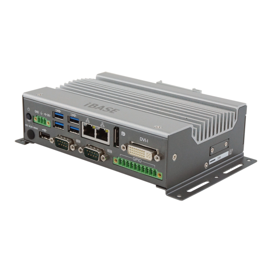
Page 13: Overview - Ags100
LED Indicator for HDD, WLAN, Wall Mount Kit WWAN DC-In Power Connector (3 pins) Antenna Holes USB 3.0 Ports Audio Line-Out Jack COM1 & COM2 RS-232/422/485 GbE LAN Ports Ports DisplayPort Nano SIM Slot Door AGS100 & AGS102 User Manual... - Page 14 General Information Wall Mount DIN Rail Mount (Optional) AGS100 & AGS102 User Manual...
-
Page 15: Overview - Ags102
Wall Mount Kit DC-In Power Connector (3 pins) Antenna Holes USB 3.0 Ports Audio Line-Out Jack COM1 ~ COM4 Ports GbE LAN Ports (COM1 & COM2 RS-232/422/485, COM3 & COM4 RS-232 Ports) DisplayPort Nano SIM Slot Door AGS100 & AGS102 User Manual... - Page 16 General Information Wall Mount DIN Rail Mount (Optional) AGS100 & AGS102 User Manual...
-
Page 17: Dimensions - Ags100
1.8 Dimensions – AGS100 Unit: mm 1.9 Dimensions – AGS102 Unit: mm AGS100 & AGS102 User Manual... -
Page 18: Chapter 2 Hardware Configuration
Chapter 2 Hardware Configuration The information provided in this chapter includes: • Essential installations before you begin • Information and locations of connectors... -
Page 19: Installations
To remove the module, press the clips outwards with both hands, and the module will pop-up.Locate the memory slots in your device. AGS100 & AGS102 User Manual... -
Page 20: Mini-Pcie & M.2 Cards Installation / Replacement
1. Thread and fasten the hex nut and the 2. Apply adhesive around here. washer. Then install the antenna. Info: The diameter of the nut is around 6.35 mm (0.25”-36UNC). AGS100 & AGS102 User Manual... -
Page 21: Mounting Installation
Wall-Mounting Installation 1. Turn your product upside down to attach the mounting brackets to your product and secure with the supplied 4 screws. 2. Prepare at least 4 screws (M3) to install the device on wall. AGS100 & AGS102 User Manual... - Page 22 2 screws. 2. Hook the DIN rail mounting bracket over the top of the DIN rail, and then press the lower section of the bracket towards the DIN rail to clip the bracket onto it. AGS100 & AGS102 User Manual...
-
Page 23: Pinout For Com Ports & Dc-In Power Connector
DSR, Data set ready RXD, Receive data RTS, Request to send TXD, Transmit data CTS, Clear to send DTR, Data terminal ready RI, Ring indicator Ground Assignment RS-232 RS-422 RS-485 DATA- DATA+ Ground Ground Ground AGS100 & AGS102 User Manual... - Page 24 DC-In Power Connector (3-pin terminal block) Assigment Assigment Power Ground 9V ~ 36V Case Ground 2.1.5.4. Isolated 4-In & 4-Out GPIO Connector (10-pin terminal block) Assigment Assigment Isolation +5V OUT0 OUT1 OUT2 OUT3 Isolation Ground AGS100 & AGS102 User Manual...
-
Page 25: Setting The Jumpers
When two pins of a jumper are encased in a jumper cap, this jumper is closed, i.e. turned On. When a jumper cap is removed from two jumper pins, this jumper is open, i.e. turned Off. AGS100 & AGS102 User Manual... -
Page 26: Motherboard Jumper & Connector Locations
Hardware Configuration 2.3 Motherboard Jumper & Connector Locations Motherboard: IB801 IB801 - Top AGS100 & AGS102 User Manual... - Page 27 IB801 - Bottom AGS100 & AGS102 User Manual...
-
Page 28: Motherboard Jumpers Quick Reference
Clearing ME Register Clearing CMOS Data Factory Use Only JP4, 2.4.1 Clearing ME Register (JP1) Function Pin closed Illustration Normal (default) Clear ME Register 2.4.2 Clearing CMOS Data (JP2) Function Pin closed Illustration Normal (default) Clear CMOS AGS100 & AGS102 User Manual... -
Page 29: Motherboard Connectors Quick Reference
M.2 E2230 Slot Mini-PCIe Slot LED Indicators LED2 (for M.2 B3042), LED3 (for WLAN), LED4 (for HDD) Factory Use Only J2, J7, J8, J9 [1], [2]: Refer to 2.1.5 Pinout for COM Ports & DC-In Power Connector. AGS100 & AGS102 User Manual... -
Page 30: Battery Connector (Bat1)
Hardware Configuration 2.5.1 Battery Connector (BAT1) Assignment Assignment Battery+ Ground 2.5.2 Reset Button Connector (J1) Assignment Assignment Ground Reset BTN 2.5.3 Power Button Connector (J3) Assignment Assignment Ground Power BTN AGS100 & AGS102 User Manual... -
Page 31: Board-To-Board Connector (J11)
(COM4) RTS, Request to (COM4) DCD, Data carrier send detect (COM4) CTS, Clear to send (COM4) RXD, Receive data (COM4) RI, Ring indicator (COM4) TXD, Transmit data (COM4) DTR, Data terminal USB_D+ ready USB_D- Ground Ground 5VDUAL AGS100 & AGS102 User Manual... -
Page 32: Carrier Board Connectors Quick Reference (For Ags102 Only)
[1]: Refer to 2.1.5.2 COM3 & COM4 RS-232 Port (for AGS102 only). [2]: Refer to 2.1.5.4 Isolated 4-In & 4-Out GPIO Connector (10-pin terminal block). [3]: Refer to 2.5.4 Board-to-Board Connector (J11) for the pinout. AGS100 & AGS102 User Manual... -
Page 33: Chapter 3 Driver Installation
Chapter 3 Driver Installation The information provided in this chapter includes: • ® Intel Chipset Software Installation Utility • Graphics Driver Installation • HD Audio Driver Installation • ® Intel Trusted Execution Engine Drivers Installation • ® Intel Serial I/O Drivers •... -
Page 34: Introduction
INF files for Plug & Play function for the chipset components. Follow the instructions below to complete the installation. 1. Insert the disk enclosed in the package. Click Intel and then Intel(R) Apollolake Chipset Drivers. 2. Click Intel(R) Chipset Software Installation Utility. AGS100 & AGS102 User Manual... - Page 35 4. Accept the software license agreement to continue. 5. On the Readme File Information screen, click Install and then Next. 6. When the driver is completely installed, click Finish and restart the computer for changes to take effect. AGS100 & AGS102 User Manual...
-
Page 36: Graphics Driver Installation
Driver Installation 3.3 Graphics Driver Installation 1. Click Intel and then Intel(R) Apollolake Chipset Drivers. 2. Click Intel(R) Apollolake Graphics Driver. 3. When the Welcome screen appears, click Next to continue. AGS100 & AGS102 User Manual... - Page 37 5. Read the Readme File Information and then click Next until the installation starts. 6. Choose a destination folder for installation. 7. When the driver is completely installed, click Finish and restart the computer for changes to take effect. AGS100 & AGS102 User Manual...
-
Page 38: Hd Audio Driver Installation
2. Click Realtek High Definition Audio Driver. 3. On the Welcome screen of the InstallShield Wizard, click Next until the installation starts. 4. When the driver is completely installed, click Finish and restart the computer for changes to take effect. AGS100 & AGS102 User Manual... -
Page 39: Intel Trusted Execution Engine Driver Installation
3. When the Welcome screen appears, click Next to continue. 4. Accept the licence agreement and click Next to continue. 5. When the driver is completely installed, click Finish and restart the computer for changes to take effect. AGS100 & AGS102 User Manual... -
Page 40: Usb 3.1 Driver Installation
1. Click Intel and then Intel(R) Apollolake Chipset Drivers. 2. Click Intel(R) Serial IO Drivers. 3. When the Welcome screen appears, click Next to continue. 4. When the driver is completely installed, click Finish and restart the computer for changes to take effect. AGS100 & AGS102 User Manual... -
Page 41: Lan Driver Installation
1. Click LAN Card on the left and then Intel(R) I21x Giagabit Network Drivers 2. When the Welcome screen appears, click Next to continue. 3. Tick the checkboxes to select the related drivers and click Next. AGS100 & AGS102 User Manual... - Page 42 Driver Installation 4. When the wizard is ready for installation, click Install. 5. When the driver is completely installed, click Finish and restart the computer for changes to take effect. AGS100 & AGS102 User Manual...
-
Page 43: Chapter 4 Bios Setup
Chapter 4 BIOS Setup This chapter describes the different settings available in the AMI BIOS that comes with the board. The topics covered in this chapter are as follows: • Main Settings • Advanced Settings • Chipset Settings • Security Settings •... -
Page 44: Introduction
These defaults have been carefully chosen by both AMI and your system manufacturer to provide the absolute maximum performance and reliability. Changing the defaults could make the system unstable and crash in some cases. AGS100 & AGS102 User Manual... -
Page 45: Main Settings
4.3 Main Settings BIOS Setting Description System Date Sets the date. Use the <Tab> key to switch between the data elements. System Time Set the time. Use the <Tab> key to switch between the data elements. AGS100 & AGS102 User Manual... -
Page 46: Advanced Settings
Shows super IO monitor hardware status. Hardware Monitor CPU Configuration Displays CPU configuration parameters. Network Stack Enables / Disables UEFI Network Stack. Configuration CSM Configuration Enables / Disables option ROM execution settings, etc. USB Configuration Displays USB configuration parameters. AGS100 & AGS102 User Manual... -
Page 47: Acpi Settings
Enables / Disables the system ability to hibernate (OS/S4 Sleep State). This option may not be effective with some OS. ACPI Sleep State Selects a ACPI sleep state for the system to enter. Options: Suspend Disabled, S3 (Suspend to RAM) AGS100 & AGS102 User Manual... -
Page 48: Ismart Controller
For example, if setting up a schedule from Wednesday 5 p.m. to Thursday 2 a.m., configure two schedule slots. But if setting up a schedule from 3 p.m to 5 p.m. on Wednesday, configure only a schedule slot. AGS100 & AGS102 User Manual... -
Page 49: Fintek Super Io Configuration
4.4.3 Fintek Super IO Configuration BIOS Setting Description Serial Port Configuration Sets Parameters of Serial Ports. You can enable / disable the serial port and select an optimal settings for the Super IO device. AGS100 & AGS102 User Manual... - Page 50 IO = 3E8h; IRQ = 3, 4, 5, 6, 7, 9, 10, 11, 12 • IO = 2E8h; IRQ = 3, 4, 5, 6, 7, 9, 10, 11, 12 Device Mode Serial port 1 loop back / RS232 / RS422 / RS485 mode select. AGS100 & AGS102 User Manual...
- Page 51 IO = 3E8h; IRQ = 3, 4, 5, 6, 7, 9, 10, 11, 12 • IO = 2E8h; IRQ = 3, 4, 5, 6, 7, 9, 10, 11, 12 Device Mode Serial port 1 loop back / RS232 / RS422 / RS485 mode select. AGS100 & AGS102 User Manual...
- Page 52 IO = 2E8h; IRQ = 3, 4, 5, 6, 7, 9, 10, 11, 12 • IO = 2F0h; IRQ = 3, 4, 5, 6, 7, 9, 10, 11, 12 • IO = 2E0h; IRQ = 3, 4, 5, 6, 7, 9, 10, 11, 12 AGS100 & AGS102 User Manual...
- Page 53 IO = 2E8h; IRQ = 3, 4, 5, 6, 7, 9, 10, 11, 12 • IO = 2F0h; IRQ = 3, 4, 5, 6, 7, 9, 10, 11, 12 • IO = 2E0h; IRQ = 3, 4, 5, 6, 7, 9, 10, 11, 12 AGS100 & AGS102 User Manual...
-
Page 54: Fintek Hardware Monitor
The values are read-only as monitored by the system and showing the PC health status CPU Shutdown This field enables or disables the Shutdown Temperature Temperature Options: Disabled (default),. 70°C, 75°C, 80°C, 85°C, 90°C, 95°C AGS100 & AGS102 User Manual... -
Page 55: Cpu Configuration
Socket specific CPU Information CPU Power Management The turbo mode is activable for CPU power management. Monitor Mwait Enables / Disables Monitor Mwait. 4.4.6 Network Stack Configuration BIOS Setting Description Network Stack Enables / Disables UEFI Network Stack. AGS100 & AGS102 User Manual... -
Page 56: Csm Configuration
Storage Controls the execution of UEFI and Legacy Storage OpROM. Video Controls the execution of UEFI and Legacy Video OpROM. Other PCI devices Determines OpROM execution policy for devices other than network, storage or video. AGS100 & AGS102 User Manual... -
Page 57: Usb Configuration
The maximum time the device will take before it properly reports itself to the Host Controller. Auto uses default value. For a Root port, it is 100 ms. For a Hub port, the delay is taken from Hub descriptor. AGS100 & AGS102 User Manual... -
Page 58: Chipset Settings
4.5 Chipset Settings BIOS Setting Description HD-Audio Configuration HD audio configuration settings PCI Express PCI Express Configuration Settings Configuration SATA Drives Press Enter to select the SATA device configuration setup options. USB Configuration USB configuration settings AGS100 & AGS102 User Manual... -
Page 59: Hd-Audio Configuration
Enables / Disables HD audio support. 4.5.2 PCI Express Configuration BIOS Setting Description PCI Express Root Port 1 Enables / Disables the PCI Express root port. Auto: Disables unused root port automatically for the most optimum power savings. AGS100 & AGS102 User Manual... - Page 60 Options: Disable, L0s, L1, L0sL1, Auto L1 Substates PCI Express L1 substates settings. Options: Disabled, L1.1, L1.2, L1.1 & L1.2 PME SCI Enables / Disables PCI Express PME SCI. PCIe Speed Configures PCIe speed. Options: Auto, Gen1, Gen2 AGS100 & AGS102 User Manual...
-
Page 61: Sata Drives
Enables / Disables the Chipset SATA controller. The Chipset SATA controller supports the 2 black internal SATA ports (up to 3 Gb/s supported per port). SATA Mode Selection Determines how SATA controller(s) operation. Option: AHCI AGS100 & AGS102 User Manual... -
Page 62: Usb Configuration
Enables / Disables XHCI pre-boot driver support. XHCI Mode Once disbled, XHCI controller would be function disabled. None of the USB devices are detectable and usable during boot and in OS. Do not disable it unless for debug purpose. AGS100 & AGS102 User Manual... -
Page 63: Security Settings
4.6 Security Settings BIOS Setting Description Setup Administrator Sets an administrator password for the setup Password utility. User Password Sets a user password. AGS100 & AGS102 User Manual... -
Page 64: Boot Settings
Selects a Boot mode, Legacy / UEFI. Boot Option Priorities Sets the system boot order priorities for hard disk, CD/DVD, USB, Network. UEFI Hard Disk Drive Specifies the boot device priority sequence from BBS Priorities available UEFI hard disk drives. AGS100 & AGS102 User Manual... -
Page 65: Save & Exit Settings
Restores / Loads defaults values for all the setup options. Save as User Defaults Saves the changes done so far as user defaults. Restore User Defaults Restores the user defaults to all the setup options. AGS100 & AGS102 User Manual... -
Page 66: Appendix
Appendix This section provides the mapping addresses of peripheral devices and the sample code of watchdog timer configuration. • I/O Port Address Map • Interrupt Request Lines (IRQ) • Watchdog Timer Configuration... -
Page 67: I/O Port Address Map
Motherboard resources 0x00000500-0x000005FE Motherboard resources 0x00000600-0x0000061F Motherboard resources 0x0000164E-0x0000164F Motherboard resources 0x0000F040-0x0000F05F Intel(R) Celeron(R)/Pentium(R) Processor SMBUS - 5AD4 0x0000D000-0x0000DFFF Intel(R) Celeron(R)/Pentium(R) Processor PCI Express Root Port - 5AD9 0x00000020-0x00000021 Programmable interrupt controller 0x00000024-0x00000025 Programmable interrupt controller AGS100 & AGS102 User Manual... - Page 68 0x00000000-0x0000006F PCI Express Root Complex 0x00000078-0x00000CF7 PCI Express Root Complex 0x00000D00-0x0000FFFF PCI Express Root Complex 0x0000E000-0x0000EFFF Intel(R) Celeron(R)/Pentium(R) Processor PCI Express Root Port - 5AD8 0x00000040-0x00000043 System timer 0x00000050-0x00000053 System timer 0x0000F000-0x0000F03F Intel(R) HD Graphics AGS100 & AGS102 User Manual...
-
Page 69: Interrupt Request Lines (Irq)
IRQ 14 Intel(R) Serial IO GPIO Host Controller - INT3452 IRQ 14 Intel(R) Serial IO GPIO Host Controller - INT3452 IRQ 0 System timer IRQ 4294967292 Intel(R) Trusted Execution Engine Interface IRQ 4294967293 Intel(R) HD Graphics AGS100 & AGS102 User Manual... -
Page 70: Watchdog Timer Configuration
SIO; printf("Fintek 81866 watch dog program\n"); SIO = Init_F81964(); if (SIO == 0) printf("Can not detect Fintek 81866, program abort.\n"); return(1); }//if (SIO == 0) if (argc != 2) printf(" Parameter incorrect!!\n"); return (1); AGS100 & AGS102 User Manual... - Page 71 DisableWDT(void) unsigned char bBuf; Set_F81964_LD(0x07); //switch to logic device 7 bBuf = Get_F81964_Reg(0xFA); bBuf &= ~0x01; Set_F81964_Reg(0xFA, bBuf); //disable WDTO output bBuf = Get_F81964_Reg(0xF5); bBuf &= ~0x20; bBuf |= 0x40; Set_F81964_Reg(0xF5, bBuf); //disable WDT //--------------------------------------------------------------------------- AGS100 & AGS102 User Manual...
- Page 72 //Fintek 81866 goto Init_Finish; } F81964_BASE = 0x00; result = F81964_BASE; Init_Finish: return (result); //--------------------------------------------------------------------------- void Unlock_F81964 (void) outportb(F81964_INDEX_PORT, F81964_UNLOCK); outportb(F81964_INDEX_PORT, F81964_UNLOCK); //--------------------------------------------------------------------------- void Lock_F81964 (void) outportb(F81964_INDEX_PORT, F81964_LOCK); //--------------------------------------------------------------------------- void Set_F81964_LD( unsigned char LD) Unlock_F81964(); AGS100 & AGS102 User Manual...
- Page 73 (F81964_BASE+1) //--------------------------------------------------------------------------- #define F81964_REG_LD 0x07 //--------------------------------------------------------------------------- #define F81964_UNLOCK 0x87 #define F81964_LOCK 0xAA //--------------------------------------------------------------------------- unsigned int Init_F81964(void); void Set_F81964_LD( unsigned char); void Set_F81964_Reg( unsigned char, unsigned char); unsigned char Get_F81964_Reg( unsigned char); //--------------------------------------------------------------------------- #endif // F81964_H AGS100 & AGS102 User Manual...
Need help?
Do you have a question about the AGS100 and is the answer not in the manual?
Questions and answers