Table of Contents
Advertisement
Quick Links
Advertisement
Table of Contents

Related Manuals for IBASE Technology IPPC A9-RE Series


Summary of Contents for IBASE Technology IPPC A9-RE Series
- Page 1 IPPCxxA9-RE Series User Manual 2013 Nov V1...
- Page 3 IPPCxxA9-RE User Manual Copyright © 2013 All Rights Reserved. No part of this manual, including the products and software described in it, may be reproduced, transmitted, transcribed, stored in a retrieval system, or translated into any language in any form or by any means, except documentation kept by the purchaser for backup purposes, without the express written permission of the author.
-
Page 4: Table Of Contents
IPPCxxA9-RE User Manual Table of Contents Safety Information ......................iii Setting up your system ....................v Care during use ......................iv Acknowledgments ......................v CHAPTER 1 INTRODUCTION ................... 1 1.1 General Description ....................1 1.2 System Specification ....................2 1.2.1 Hardware Specifications ..................2 1.2.2 Dimensions ...................... -
Page 5: Safety Information
Safety Information Your IPPCxxA9-RE is designed and tested to meet the latest standards of safety for information technology equipment. However, to ensure your safety, it is important that you read the following safety instructions Setting up your system Read and follow all instructions in the documentation before you operate your system. -
Page 6: Care During Use
IPPCxxA9-RE User Manual Care during use Do not walk on the power cord or allow anything to rest on it. Do not spill water or any other liquids on your system. When the system is turned off, a small amount of electrical current still flows. Always unplug all power, and network cables from the power outlets before cleaning the system. -
Page 7: Acknowledgments
Acknowledgments AMI is a registered trademark of AMI Software International, Inc. AMD and ATI are registered trademarks of AMD Corporation. Microsoft Windows is a registered trademark of Microsoft Corporation. FINTEK is a registered trademark of FINTEK Electronics Corporation. REALTEK is a registered trademark of REALTEK Electronics Corporation. All other product names or trademarks are properties of their respective owners. -
Page 9: Chapter 1 Introduction
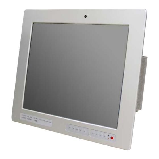
IPPCxxA9-RE User Manual CHAPTER 1 INTRODUCTION 1.1 General Description IPPCxxA9-RE series is a fanless-design panel pc, powered by 2nd Generation ® Intel Core i3-2340UE 1.3GHz and supports 2x SO-DIMM to fit up to 16GB DDRIII 1333MHz FSB, 4x USB connectors, 3x COM ports, support 1x SATA HDD space, 1x CFast slot, 2x PCI expansion slots and DC power 12~24V input. -
Page 10: System Specification
IPPCxxA9-RE User Manual 1.2 System Specification 1.2.1 Hardware Specifications Model Name IPPC17A9-RE IPPC19A9-RE System Mainboard IB907 ® 2nd Generation Intel Core i3-2340UE ® Chipset Intel HM76 PCH Memory 2x DDR3 1333 SO-DIMM up to 16GB 1x DVI-I connector I/O Interface 3x DB9 for COM1/2(RS-232/422/485), COM 3 (RS-232 only) 1x 10-pin terminal block for Digital I/O 2x RJ45 for GbE LAN... -
Page 11: Dimensions
1.2.2 Dimensions IPPC17A9-RE Copyright © 2013 All Rights Reserved. - Page 12 IPPCxxA9-RE User Manual IPPC19A9-RE...
-
Page 13: I/O View
1.2.3 I/O View Copyright © 2013 All Rights Reserved. -
Page 14: Packing List
IPPCxxA9-RE User Manual 1.3 Packing List Part No. Description Quantity Driver CD 1 pc Mounting Kits 1 set Power Cord 1 pc 1.4 Installation 1.4.1 Installing Memory 1. Unlock and remove 10 screws as in the picture below. - Page 15 2. After opening the back cover, please note the mating fan cable as shown. 3. Put the memory module into the socket. Copyright © 2013 All Rights Reserved.
-
Page 16: Installing Storage
IPPCxxA9-RE User Manual 4. Place the memory module into the socket and press it firmly. 1.4.2 Installing Storage 1. Unlock and remove 10 screws as shown. - Page 17 2. Unlock and remove 4 screws and SATA connector as shown. 3. Remove the four screws if you want to remove and change the HDD with a different storage capacity. Copyright © 2013 All Rights Reserved.
-
Page 18: Installing Cfast
IPPCxxA9-RE User Manual 1.4.3 Installing CFast 1. Unlock and remove the screw as shown. -
Page 19: Installing Pci Slot
1.4.4 Installing PCI slot 1. Unlock and remove the 2 screws from PCI slot cover. 2. Remove the PCI slot cover and PCI cover bracket from inside. Copyright © 2013 All Rights Reserved. - Page 20 IPPCxxA9-RE User Manual 3. Install the PCI card. 4. Put on the PCI cover bracket and lock the screw.
-
Page 21: Installing Wifi Module
1.4.5 Installing WIFI module 1. Push the WIFI module into the slot and use a screwdriver to turn the screw to its unlocked position. Copyright © 2013 All Rights Reserved. -
Page 22: Chapter 2 Motherboard Introduction
IPPCxxA9-RE User Manual CHAPTER 2 MOTHERBOARD INTRODUCTION 2.1 Introduction The IB907 motherboard is based on the latest Intel® HM76 chipset. The platform supports 3rd generation Intel® Core processor family with BGA1023 packing and feature an integrated dual-channel DDR3 memory controller as well as a graphics core. - Page 23 ® USB 2.0 Intel HM76 integrated USB 2.0 host controller: 1. 4ports in the rear panel (2x USB2.0; 2x USB3.0) 2. 2 ports (USB3.0) via edge golden-finger for connector ID912 3. 2 ports via onboard Mini-PCIE 4. 2 ports via edge golden-finger for connecting with ID912 5.
- Page 24 IPPCxxA9-RE User Manual Onboard 1x power button Button/Switch Watchdog Timer Yes (256 segments, 0, 1, 2…255 sec/min) Power MSP430G2433 management Power Connector Standard ATX connector for AT (default)/ATX mode RoHS Golden Finger A. PCIE(x16) golden finger x 1 for connecting to IP931 which has the following signals: - PCIe(1x) x1, PCI x3 (via ITE IT8892) - COM(TTL) x 1, USB 2.0 x 1...
-
Page 25: Installing The Memory
2.2 Installing the Memory The IB907 board supports two DDR3 memory sockets for a maximum total memory of 16GB in DDR3 SO-DIMM memory type. Installing and Removing Memory Modules To install the DDR3 modules, locate the memory slot on the board and perform the following steps: 1. -
Page 26: Setting Jumpers
IPPCxxA9-RE User Manual 2.3 Setting Jumpers Jumpers are used on IB907 to select various settings and features according to your needs and applications. Contact your supplier if you have doubts about the best configuration for your needs. The following lists the connectors on IB970 and their respective functions. - Page 27 JP2: COM1 RS232 RI/+5V/+12V Power Setting Setting Function Pin 1-2 +12V Short/Closed Pin 3-4 Short/Closed Pin 5-6 Short/Closed JP3: COM2 RS232 RI/+5V/+12V Power Setting Setting Function Pin 1-2 +12V Short/Closed Pin 3-4 Short/Closed Pin 5-6 Short/Closed Copyright © 2013 All Rights Reserved.
-
Page 28: Connectors
IPPCxxA9-RE User Manual 2.4 Connectors Connector Locations on IB907 CN1: COM1 and COM2 Serial Ports Pin # Signal Name RS-232 R2-422 RS-485 DATA- DATA+ Ground Ground Ground... - Page 29 CN2: COM3 and DVI-I Connector Signal Name Pin # Pin # Signal Name Data carrier detect DSR, Data set ready RXD, Receive data RTS, Request to send TXD, Transmit data CTS, Clear to send Data terminal ready RI, Ring indicator GND, ground Not Used Signal Name...
- Page 30 IPPCxxA9-RE User Manual CN8: Digital I/O Connector (4 in, 4 out) Pin # Digital I/O VCC5 (1A) OUT0 OUT1 OUT2 OUT3 J1: MCU Flash Connector (factory use only) J2, J3: SATA HDD Power Connector Pin # Signal Name Ground Ground +12V J4: Front Panel Function Connector Signal Name...
- Page 31 J9: ATX Power Supply Connector Signal Name Pin # Pin # Signal Name 3.3V 3.3V -12V 3.3V Ground Ground PS-ON Ground Ground Ground Ground Ground Power good 5VSB +12V J8: DDR SO-DIMM Channel A J13: DDR SO-DIMM Channel B J10: Mini-PCIE Connector J11: Mini-PCIE Connector and mSATA/share J12, J14: SATA3 Connector J15: SRAM CPLD Flash Connector (factory use only)
- Page 32 IPPCxxA9-RE User Manual J17: ATX 12V Power Connector This connector supplies the CPU operating voltage. Pin # Signal Name Ground Ground +12V +12V J18: Smart Battery Interface Connector Pin # Signal Name EXTSMI Ground DATA J19: LPC Debug Connector (factory use only) SYS_FAN1: CPU Fan Power Connector Pin # Signal Name...
-
Page 33: Chapter 3 Bios Setup
CHAPTER 3 BIOS SETUP 3.1 BIOS Introduction The BIOS (Basic Input/Output System) installed in your computer system’s ROM supports Intel processors. The BIOS provides critical low-level support for a standard device such as disk drives, serial ports and parallel ports. It also password protection as well as special support for detailed fine-tuning of the chipset controlling the entire system. -
Page 34: Main Settings
IPPCxxA9-RE User Manual 3.3 Main Settings Aptio Setup Utility – Copyright © 2011 American Megatrends, Inc. Advanced Main Chipset Boot Security Save & Exit BIOS Information Choose the system default language System Language [English] → ← Select Screen ↑↓ System Date [Tue 01/20/2009] Select Item Enter: Select... - Page 35 Advanced Settings This section allows you to configure and improve your system and allows you to set up some system features according to your preference. Aptio Setup Utility Main Advanced Chipset Boot Security Save & Exit ► PCI Subsystem Settings ►...
- Page 36 IPPCxxA9-RE User Manual PCI Subsystem Settings Aptio Setup Utility Chipset Boot Security Save & Exit Main Advanced PCI Bus Driver Version PCI 64bit Resources Handing Above 4G Decoding Disabled → ← Select Screen ↑↓ PCI Common Settings Select Item Enter: Select PCI Latency Timer 32 PCI Bus Change Field...
- Page 37 PCI Express Settings Aptio Setup Utility Chipset Boot Security Save & Exit Main Advanced PCI Express Device Register Settings Relaxed Ordering Disabled Extended Tag Disabled No Snoop Enabled Maximum Payload Auto Maximum Read Request Auto → ← Select Screen PCI Express Link Register Settings ↑↓...
- Page 38 IPPCxxA9-RE User Manual Link Training Timeout (uS) Defines number of Microseconds software will wait before polling ‘Link Training’ bit in Link Status register. Value range from 10 to 1000 uS. Unpopulated Links In order to save power, software will disable unpopulated PCI Express links, if this option set to ‘Disable Link’.
- Page 39 Wake up event settings Aptio Setup Utility Chipset Boot Security Save & Exit Main Advanced → ← Select Screen Wake on Ring Disabled ↑↓ Select Item Wake on PCI PME Disabled Enter: Select Change Field Wake on PCIE Wake Event Disabled F1: General Help F2: Previous Values...
- Page 40 IPPCxxA9-RE User Manual Hyper-threading Enabled for Windows XP and Linux (OS optimized for Hyper-Threading Technology) and Disabled for other OS (OS not optimized for Hyper-Threading Technology). When Disabled, only one thread per enabled core is enabled. Active Processor Cores Number of cores to enable in each processor package. Limit CPUID Maximum Disabled for Windows XP.
- Page 41 SATA Configuration SATA Devices Configuration. Aptio Setup Utility Chipset Boot Security Save & Exit Main Advanced SATA Controller(s) Enabled SATA Mode Selection SATA Port0 Empty Software Preserve Unknown SATA Port1 Empty Software Preserve Unknown → ← Select Screen SATA Port2 Empty ↑↓...
- Page 42 IPPCxxA9-RE User Manual Shutdown Temperature Configuration Aptio Setup Utility Boot Security Save & Exit Main Advanced Chipset → ← Select Screen APCI Shutdown Temperature Disabled ↑↓ Select Item Enter: Select Change Field F1: General Help F2: Previous Values F3: Optimized Default F4: Save ESC: Exit ACPI Shutdown Temperature...
- Page 43 Acoustic Management Configuration Aptio Setup Utility Advanced Main Chipset Boot Security Save & Exit Acoustic Management Configuration → ← Select Screen ↑↓ Acoustic Management Disabled Select Item Enter: Select Change Field F1: General Help F2: Previous Values F3: Optimized Default F4: Save ESC: Exit USB Configuration...
- Page 44 IPPCxxA9-RE User Manual XHCI Hand-off This is a workaround for OSes without XHCI hand-off support. The XHCI ownership change should be claimed by XHCI driver. EHCI Hand-off Enabled/Disabled. This is a workaround for OSes without EHCI hand-off support. The EHCI ownership change should be claimed by EHCI driver. USB Transfer time-out The time-out value for Control, Bulk, and Interrupt transfers.
- Page 45 F81866 Super IO Configuration Aptio Setup Utility Chipset Boot Security Save & Exit Main Advanced Super IO Configuration F81866 F81866 Super IO Chip → ← Select Screen ↑↓ F81866 ERP Support All Enable Select Item ► Serial Port 0 Configuration Enter: Select ►...
-
Page 46: Chipset Settings
IPPCxxA9-RE User Manual CPU PPM Configuration Aptio Setup Utility Chipset Boot Security Save & Exit Main Advanced CPU PPM Configuration → ← Select Screen ↑↓ Select Item EIST Enabled Enter: Select Change Field F1: General Help F2: Previous Values F3: Optimized Default F4: Save ESC: Exit EIST... - Page 47 PCH-IO Configuration This section allows you to configure the North Bridge Chipset. Aptio Setup Utility Main Advanced Chipset Boot Security Save & Exit Intel PCH RC Version 1.1.0.0 Intel PCH SKU Name HM76 Intel PCH Rev ID O4/C1 ► PCI Express Configuration ►...
- Page 48 IPPCxxA9-RE User Manual PCI Express Configuration Aptio Setup Utility Boot Security Save & Exit Main Advanced Chipset PCI Express Configuration PCI Express Clock Gating Enabled DMI Link ASPM Control Enabled DMI Link Extended Synch Control Disabled PCIe-USB Glitch W/A Disabled Subtractive Decode Disabled ►...
- Page 49 USB Configuration Aptio Setup Utility Boot Security Save & Exit Main Advanced Chipset USB Configuration XHCI Pre-Boot Driver Disabled xHCI Mode Auto HS Port #1 Switchable Enabled HS Port #2 Switchable Enabled HS Port #3 Switchable Enabled HS Port #4 Switchable Enabled →...
- Page 50 IPPCxxA9-RE User Manual PCH Azalia Configuration Aptio Setup Utility Main Advanced Chipset Boot Security Save & Exit PCH Azalia Configuration → ← Select Screen ↑↓ Azalia Auto Select Item Enter: Select Change Field F1: General Help F2: Previous Values F3: Optimized Default F4: Save ESC: Exit Azalia...
- Page 51 Graphics Configuration Aptio Setup Utility Security Save & Exit Main Advanced Chipset Boot Graphics Configuration IGFX VBIOS Version 2137 → ← Select Screen IGfx Frequency 650 MHz ↑↓ Select Item Primary Display Auto Enter: Select Internal Graphics Auto Change Field GTT Size F1: General Help Aperture Size...
- Page 52 IPPCxxA9-RE User Manual Memory Configuration Aptio Setup Utility Security Save & Exit Main Advanced Chipset Boot Memory Information Memory Frequency 1333 MHz Total Memory 2048 MB (DDR3) DIMM#0 2048 MB (DDR3) → ← Select Screen DIMM#1 ↑↓ DIMM#2 Select Item DIMM#3 Enter: Select CAS Latency (tCL)
- Page 53 Boot Settings This section allows you to configure the boot settings. Aptio Setup Utility Main Advanced Chipset Boot Security Save & Exit Boot Configuration Setup Prompt Timeout Bootup NumLock State Quiet Boot Disabled → ← Select Screen Fast Boot Disabled ↑↓...
- Page 54 IPPCxxA9-RE User Manual CSM parameters This section allows you to configure the boot settings. Aptio Setup Utility Main Advanced Chipset Security Save & Exit Boot → ← Select Screen Launch CSM Always ↑↓ Boot option filter UEFI and Legacy Select Item Launch PXE OpROM policy Do not launch Enter: Select...
- Page 55 Security Settings This section allows you to configure and improve your system and allows you to set up some system features according to your preference. Aptio Setup Utility Main Advanced Chipset Boot Security Save & Exit Password Description If ONLY the Administrator’s password is set, then this only limit access to Setup and is only asked for when entering Setup.
- Page 56 IPPCxxA9-RE User Manual Save & Exit Settings Aptio Setup Utility Main Advanced Chipset Boot Security Save & Exit Save Changes and Exit Discard Changes and Exit Save Changes and Reset → ← Select Screen Discard Changes and Reset ↑↓ Select Item Save Options Enter: Select Save Changes...
-
Page 57: Chapter 4 Drivers Installation
CHAPTER 4 DRIVERS INSTALLATION This section describes the installation procedures for software and drivers. The software and drivers are included with the motherboard. IMPORTANT NOTE: After installing your Windows operating system, you must install first the Intel Chipset Software Installation Utility before proceeding with the drivers installation. 4.1 Intel Chipset Software Installation Utility The Intel Chipset Drivers should be installed first before the software drivers to enable Plug &... - Page 58 IPPCxxA9-RE User Manual 2. Click Intel(R) Chipset Software Installation Utility.. 3. When the Welcome screen to the Intel® Chipset Device Software appears, click Next to continue.
- Page 59 4. Click Yes to accept the software license agreement and proceed with the installation process. 5. On the Readme File Information screen, click Next to continue the installation. 6. The Setup process is now complete. Click Finish to restart the computer and for changes to take effect.
-
Page 60: Vga Drivers Installation
IPPCxxA9-RE User Manual 4.2 VGA Drivers Installation NOTE: Before installing the Intel(R) 7 Series Chipset Family Graphics Driver, the Microsoft .NET Framework 3.5 SPI should be first installed. To install the VGA drivers, follow the steps below. 1. Insert the CD that comes with the board. Click Intel and then Intel(R) 7 Series Chipset Drivers. - Page 61 3. When the Welcome screen appears, click Next to continue. 4. Click Yes to to agree with the license agreement and continue the installation. Copyright © 2013 All Rights Reserved.
- Page 62 IPPCxxA9-RE User Manual 5. On the Readme File Information screen, click Next to continue the installation of the Intel® Graphics Media Accelerator Driver. 6. On Setup Progress screen, click Next to continue. 7. Setup complete. Click Finish to restart the computer and for changes to take effect.
-
Page 63: Realtek Hd Audio Driver Installation
4.3 Realtek HD Audio Driver Installation Follow the steps below to install the Realtek HD Audio Drivers. 1. Insert the CD that comes with the board. Click Intel and then Intel(R) 7 Series Chipset Drivers. 2. Click Realtek High Definition Audio Driver. Copyright ©... - Page 64 IPPCxxA9-RE User Manual 3. On the Welcome to the InstallShield Wizard screen, click Next to proceed with and complete the installation process. 4. The InstallShield Wizard Complete. Click Finish to restart the computer and for changes to take effect.
-
Page 65: Lan Drivers Installation
4.4 LAN Drivers Installation 1. Insert the CD that comes with the board. Click Intel and then Intel(R) 7 Series Chipset Drivers. 2. Click Intel(R) PRO LAN Network Driver. Copyright © 2013 All Rights Reserved. - Page 66 IPPCxxA9-RE User Manual 3. Click Install Drivers and Software. 4. When the Welcome screen appears, click Next.
- Page 67 5. Click Next to to agree with the license agreement. 6. Click the checkbox for Drivers in the Setup Options screen to select it and click Next to continue. Copyright © 2013 All Rights Reserved.
- Page 68 IPPCxxA9-RE User Manual 7. The wizard is ready to begin installation. Click Install to begin the installation. 8. When InstallShield Wizard is complete, click Finish.
-
Page 69: Realtek Lan Controller Drivers Installation
4.5 Realtek LAN Controller Drivers Installation Follow the steps below to install the Realtek LAN Drivers. 1. Insert the CD that comes with the board. Click Intel, then LAN Card, and then Realtek LAN Controller Drivers. 2. Click Realtek RTL8111E LAN Drivers. Copyright ©... - Page 70 IPPCxxA9-RE User Manual 3.When the welcome screen to InstallShield Wizard appears, click Next to start the installation 4.When the InstallShieldWizard has finished installing the Realtek LAN drivers, click Finish.
-
Page 71: Intel® Management Engine Interface
4.6 Intel® Management Engine Interface Follow the steps below to install the Intel Management Engine. 1. Insert the CD that comes with the board. Click Intel and then Intel(R) AMT 8.0 Drivers. 2. When the Welcome screen to the InstallShield Wizard for Intel® Management Engine Components, click the checkbox for Install Intel®... - Page 72 IPPCxxA9-RE User Manual 3. Click Yes to to agree with the license agreement. 4. When the Setup Progress screen appears, click Next. Then, click Finish when the setup progress has been successfully installed.
-
Page 73: Intel® Usb 3.0 Drivers
4.7 Intel® USB 3.0 Drivers 1. Insert the CD that comes with the board. Click Intel and then Intel(R) 7 Series Chipset Drivers. 2. Click Intel(R) USB 3.0 Drivers. Copyright © 2013 All Rights Reserved. - Page 74 IPPCxxA9-RE User Manual 3. When the Welcome screen to the InstallShield Wizard for Intel® USB 3.0 eXtensible Host Controller Driver, click Next. 4. Click Yes to to agree with the license agreement and continue the installation.
- Page 75 5. On the Readme File Information screen, click Next to continue the installation of the Intel® USB 3.0 eXtensible Host Controller Driver. 6. Setup complete. Click Finish to restart the computer and for changes to take effect. Copyright © 2013 All Rights Reserved.
-
Page 76: Altera Fpga Driver Installation
IPPCxxA9-RE User Manual 4.8 ALTERA FPGA Driver Installation 1. Insert the drivers DVD into the DVD drive. Click AMD and then ALTERA FPGA Driver. 2. When the Welcome to Peripheral Controller Driver 2.0 for Windows XP/Vista Setup Wizard screen appears, click Next to continue. 3.
Need help?
Do you have a question about the IPPC A9-RE Series and is the answer not in the manual?
Questions and answers