Table of Contents
Advertisement
Quick Links
Advertisement
Table of Contents

Subscribe to Our Youtube Channel
Related Manuals for IBASE Technology AMS210


Summary of Contents for IBASE Technology AMS210
- Page 1 AMS210 Embedded System with MB211 User’s Manual Version 1.0 (March 2020)
- Page 2 No part of this publication may be reproduced, copied, stored in a retrieval system, translated into any language or transmitted in any form or by any means, electronic, mechanical, photocopying, or otherwise, without the prior written consent of IBASE Technology, Inc. (hereinafter referred to as “IBASE”).
- Page 3 0.1% by weight (1000 ppm) except for cadmium, limited to 0.01% by weight (100 ppm). • Lead (Pb) • Mercury (Hg) • Cadmium (Cd) • Hexavalent chromium (Cr6+) • Polybrominated biphenyls (PBB) • Polybrominated diphenyl ether (PBDE) AMS210 User Manual...
- Page 4 You are not suggested to disassemble, repair or make any modification to the device. Disassembly, modification, or any attempt at repair could generate hazards and cause damage to the device, even bodily injury or property damage, and will void any warranty. AMS210 User Manual...
- Page 5 Software in use (such as OS and application software, including the version numbers) 3. If repair service is required, you can download the RMA form at http://www.ibase.com.tw/english/Supports/RMAService/. Fill out the form and contact your distributor or sales representative. AMS210 User Manual...
-
Page 6: Table Of Contents
Introduction ....................2 Features ....................2 Packing List ..................... 3 Optional Accessories ................3 Specifications – AMS210 ................. 4 System View – AMS210 ................6 Dimensions – AMS210 ................8 Chapter 2 Hardware Configuration ............10 Essential Installations ................11 Setting the Jumpers ................ -
Page 7: Chapter 1 General Information
Chapter 1 General Information The information provided in this chapter includes: Features Packing List Optional Accessories Specifications Overview Dimensions... -
Page 8: Introduction
1.1 Introduction The AMS210 embedded system is based on the Intel® 9th/8th Gen. Core™/ Pentium® / Celeron® processors and houses the MB211 motherboard built with two DDR4 memory slots with a 32GB capacity. Measuring 265mm x 247mm, the system has four Gigabit Ethernet connectors, four serial ports, USB 3.1 and USB 2.0 connectors, two DP++ display ports, and 24V DC power input. -
Page 9: Packing List
Round Head Screw (for Bracket) PCI Power Cable 1.4 Optional Accessories IBASE provide the following optional accessories: ABP-IP701 riser card: PCI-e(x16) slot + PCI-e(x4) slot ABP-IP702 riser card: PCI-e(x16) slot + PCI-e slot (default) ABP-IP703 riser card: 2x PCI slots AMS210 User Manual... -
Page 10: Specifications - Ams210
1.5 Specifications – AMS210 Product AMS210 Name System Motherboard MB211 Operating Windows10 (64-bit) / 7 (32-bit & 64-bit) System ® Intel 9th/8th Gen. Core / Pentium® / Celeron® processors TDP = 35W ® Chipset Intel Q370 2 x DDR4-2666/2400 SO-DIMM; Max. 32GB... - Page 11 Operating : 0.25Grms / 5~500Hz Vibration Non-operating : 1Grms / 5~500Hz Operating : 20G / 11ms Shock Non-operating : 40G / 11ms CE / FCC Class A / LVD Certification All specifications are subject to change without prior notice. AMS210 User Manual...
-
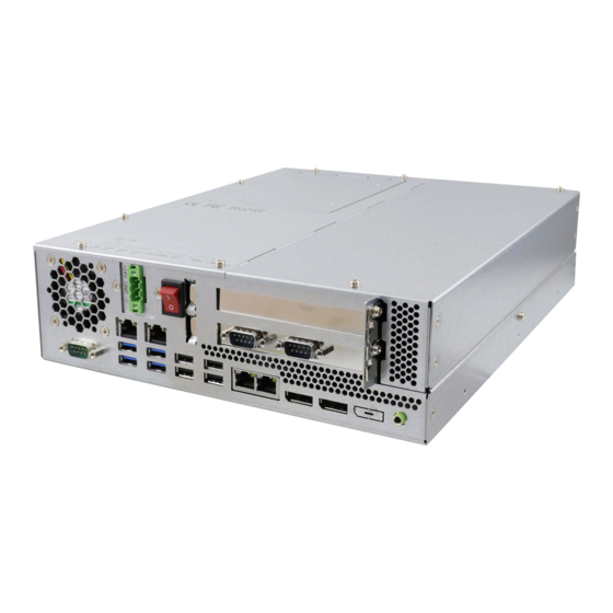
Page 12: System View - Ams210
1.6 System View – AMS210 Front View Name Name 24V Power Input USB 3.0 Ports Power Switch USB 2.0 Ports Expansion Slots DP Ports COM1 Serial Port Line Out GbE Ports AMS210 User Manual... - Page 13 Hardware Configuration Rear View Name Name Optional COM Ports BIOS POST Code DC Fan for PSU Power and HDD LEDs NVRAM Battery Compartment AMS210 User Manual...
-
Page 14: Dimensions - Ams210
1.7 Dimensions – AMS210 Unit: mm AMS210 User Manual... - Page 15 Hardware Configuration This page is intentionally left blank. AMS210 User Manual...
-
Page 16: Chapter 2 Hardware Configuration
Chapter 2 Hardware Configuration The information provided in this chapter includes: Essential installations before you begin Information and locations of connectors... -
Page 17: Essential Installations
HDD compartment cover. 2.1.1 Battery Installation The battery compartment is secured by one screw (M3x6). Unscrew the compartment cover and install the battery as shown below. Position the battery by observing the polarity. Replace the cover. AMS210 User Manual... - Page 18 After installing the card into place, secure the expansion card slot cover by using one M3*4 screw. The riser card bracket, as encircled below, can be used to secure the expansion card. Use one M3*4 screw to fasten the bracket. Replace the chassis cover. AMS210 User Manual...
- Page 19 Remove the (M3*6) screws of the HDD tray cover and pull the tray out. There are four screws securing the hard disk drive as shown below. Please note that the SATA interface connector and the HDD power interface are to be connected first during the HDD installation. AMS210 User Manual...
- Page 20 2. Locate the Mini-PCIe slot inside the system. 3. Align the key of the mini-PCIe card to the mini-PCIe interface, and insert the card slantwise. 4. Push the mini-PCIe card down and fix it with the an M2 screw. Mini PCIe: AMS210 User Manual...
- Page 21 4. Gently push the module until the clips of the slot click to hold the module in place when the module touches the bottom of the slot. 5. To remove the module, press the clips outwards with both hands. AMS210 User Manual...
-
Page 22: Setting The Jumpers
1 2 3 When two pins of a jumper are encased in a jumper cap, this jumper is closed, i.e. turned On. When a jumper cap is removed from two jumper pins, this jumper is open, i.e. turned Off. AMS210 User Manual... -
Page 23: Jumper & Connector Locations On Motherboard
2.3 Jumper & Connector Locations on Motherboard MB211 Motherboard 2.4 Jumpers Quick Reference Function Jumper Name Page Clearing CMOS Data Clearing ME Register ATX/AT Select PCIe (x16) Bifurcation Selection JP1 & JP2 PCIe_X16 Reverse Factory Use Only AMS210 User Manual... - Page 24 2.4.1 Clearing CMOS Data (JP6) Function Pin closed Illustration Normal (default) Clear CMOS 2.4.2 JP7: Clearing ME Register Function Pin closed Illustration Normal (default) Clear ME AMS210 User Manual...
- Page 25 JP1 & JP2: PCIe (x16) Bifurcation Selection Function Pin closed Illustration JP1: Open 1 x PCIe (x16) JP2: Open JP1: Open 2 x PCIe (x8) JP2: Close 1 x PCIe (x8) JP1: Close 2 x PCIe (x4) JP2: Close (default) AMS210 User Manual...
- Page 26 2.4.5 JP3: PCIe_X16 Reverse Function Pin closed Illustration Normal Open Reverse(default) Closed 2.4.6 JP8: Flash Descriptor Security Override (Factory use only) Function Pin closed Illustration Disabled Open (Default) Enabled Closed AMS210 User Manual...
-
Page 27: Connectors Quick Reference
PCI Power Connector J11,J14 Digital I/O Connector DDR4 SO-DIMM Slot J15, J16 SPI Flash Header Audio Connector PCIe (x16) Slot PCIE1 PCIe (x16) Combo Slot PCIE2 CPU Fan Connector CPU_FAN1 System Fan Connector SYS_FAN1 /2 Factory Use Only J3,J13,J19 AMS210 User Manual... - Page 28 DCD, Data carrier detect DSR, Data set ready RXD, Receive data RTS, Request to send TXD, Transmit data CTS, Clear to send DTR, Data terminal ready RI, Ring indicator Ground Signal Name RS-232 RS-422 RS-485 DATA- DATA+ Ground Ground Ground AMS210 User Manual...
- Page 29 TXD, Transmit data DTR, Data terminal ready Ground DSR, Data set ready RTS, Request to send CTS, Clear to send RI, Ring indicator 2.5.3 J12: Digital I/O Connector Signal Name Signal Name Ground OUT3 OUT1 OUT2 OUT0 AMS210 User Manual...
- Page 30 2.5.4 CPU_FAN1: CPU Fan Power Connector Signal Name Signal Name Ground Rotation detection +12V Control 2.5.5 SYS_FAN1/2: System Fan Power Connector AMS210 User Manual...
- Page 31 Hardware Configuration 2.5.6 PCIE1: PCIEx16 Slot (Including PCI-E(x16) signal) 2.5.7 PCIE2: PCIEx16 Slot (Including PCI-E(x4) & PCI signals) AMS210 User Manual...
- Page 32 2.5.8 J16: DDR SO-DIMM Channel A 2.5.9 J15: DDR SO-DIMM Channel B AMS210 User Manual...
- Page 33 Hardware Configuration 2.5.10 J1: DC-in Connector Signal Name Signal Name Power Ground +24V Power Ground +24V 2.5.11 J17: SPI Flash Connector (Factory use only) (2mm) AMS210 User Manual...
- Page 34 2.5.12 J3: LPC Debug Connector (Factory use only) (2mm) Signal Name Signal Name LPC_AD0 Reset# LPC_AD1 LPC_FRAME# LPC_AD2 +3.3V LPC_AD3 Ground CLK_33MHz Protect Pin 2.5.13 J4, J7: SATA Power Connector Signal Name Signal Name Ground Ground +12V AMS210 User Manual...
- Page 35 Hardware Configuration 2.5.14 J11,J14: PCI Power Connector Signal Name Signal Name Ground Ground +12V 2.5.15 J2: Battery 1/2AA Connector Signal Name Ground AMS210 User Manual...
- Page 36 2.5.16 CN1: Interface to ABP-ID45 2.5.17 CN5 : RJ45 (I219LM) + USB3.1 Gen1 Connector 2.5.18 CN6 : RJ45 (I210IT) + USB3.1 Gen1 Connector AMS210 User Manual...
- Page 37 Hardware Configuration 2.5.19 CN9 : Dual RJ45 I210IT Connector 2.5.20 CN10, CN13, CN14 : DP Connector AMS210 User Manual...
- Page 38 2.5.21 Audio Connector (J20) Assignment Assignment Lineout_L Lineout_R JD_FRONT Ground LINEIN_L Linein_R JD_LINEIN Ground MIC_L MIC-R JD_MIC1 Ground 2.5.22 Audio Line-OUT Connector CN12 AMS210 User Manual...
- Page 39 Hardware Configuration 2.5.23 USB 2.0 Connector CN7 / CN8 2.5.24 USB 2.0 DF11 Pin Header J18 Assignment Assignment Ground Ground AMS210 User Manual...
- Page 40 GbE LAN Port & CN2, CN3 Dual USB 3.1 Gen1 Ports PSE LAN (I210IT) CN13, CN14 Audio Connector SATA III Port CN8, CN9 DDR4 SO-DIMM Slot J3, J16 M.2 M2280 Slot M.2 E2230 Slot M.2 B3042 Slot AMS210 User Manual...
- Page 41 Hardware Configuration This page is intentionally left blank. AMS210 User Manual...
-
Page 42: Chapter 3 Driver Installation
Chapter 3 Driver Installation The information provided in this chapter includes: ® Intel Chipset Software Installation Utility Graphics Driver Installation HD Audio Driver Installation LAN Driver Installation ® Intel Management Engine Driver Installation... -
Page 43: Introduction
Chipset Device Software appears, click Next to continue. Accept the software license agreement and proceed with the installation process. On the Readme File Information screen, click Install for installation. When the driver is completely installed, restart the computer for changes to take effect. AMS210 User Manual... -
Page 44: Hd Graphics Driver Installation
3.2 HD Graphics Driver Installation 1. Click Intel(R) Coffeelake Chipset Drivers on the right pane. Click Intel(R) HD Graphics Driver. AMS210 User Manual... - Page 45 When the Welcome screen appears, click Next to continue. Accept the license agreement and click Next. On the Readme File Information screen, click Next until the installation starts. When the driver is completely installed, restart the computer for changes to take effect. AMS210 User Manual...
-
Page 46: Hd Audio Driver Installation
Click Intel(R) Coffeelake Chipset Drivers on the right pane. Click Realtek High Definition Audio Driver. On the Welcome screen of the InstallShield Wizard, click Next. Click Next until the installation starts. When the driver is completely installed, restart the computer for changes to take effect. AMS210 User Manual... -
Page 47: Lan Driver Installation
Driver Installation 3.4 LAN Driver Installation Click Intel(R) Coffeelake Chipset Drivers on the right pane. Click Intel(R) PRO LAN Network Drivers.. AMS210 User Manual... - Page 48 On the Setup Options screen, click the checkbox to select the desired driver(s) for installation. Then click Next to continue. The wizard is ready for installation. Click Install. As the installation is complete, restart the computer for changes to take effect. AMS210 User Manual...
-
Page 49: Intel® Management Engine Drivers Installation
Driver Installation 3.5 Intel® Management Engine Drivers Installation Click Intel(R) Coffeelake Chipset Drivers on the right pane. Click Intel(R) ME 12.x Drivers. AMS210 User Manual... - Page 50 When the Welcome screen appears, click Next. Accept the license agreement, choose a destination folder and click Next until the installation starts. Restart the computer when installation is complete. AMS210 User Manual...
-
Page 51: Chapter 4 Bios Setup
Chapter 4 BIOS Setup This chapter describes the different settings available in the AMI BIOS that comes with the board. The topics covered in this chapter are as follows: Main Settings Advanced Settings Chipset Settings Security Settings ... -
Page 52: Introduction
These defaults have been carefully chosen by both AMI and your system manufacturer to provide the absolute maximum performance and reliability. Changing the defaults could make the system unstable and crash in some cases. AMS210 User Manual... -
Page 53: Main Settings
System Language Choose the system default language. System Date Sets the date. Use the <Tab> key to switch between the data elements. System Time Set the time. Use the <Tab> key to switch between the data elements. AMS210 User Manual... -
Page 54: Advanced Settings
Number of cores to enable in each processor Cores package. Enable/Disable AES (Advanced Encryption Standard) Intel Trusted Enables utilization of additional hardare capabilities Execution provided by Intel (R) Trusted Execution Technology Technology. Changes require a full power cycle to take effect. AMS210 User Manual... - Page 55 BIOS Setup 4.4.2 Power & Performance BIOS Setting Description CPU – Power CPU – Power Management Control Options Management Control 4.4.3 PCH-FN Configuration Configure Management Engine Technology Parameters AMS210 User Manual...
- Page 56 (OS/S4 Sleep State). This option may not be effective with some operating systems. ACPI Sleep State Selects the highest ACPI sleep state for the system will enter when the SUSPEND button is pressed. Options: Suspend Disabled S3 (Suspend to RAM) AMS210 User Manual...
- Page 57 BIOS Setup 4.4.5 F81966 Super IO Configuration BIOS Setting Description Serial Port Sets parameters of Serial Ports. Configuration Enables / Disables the serial port and select an optimal setting for the Super IO device. AMS210 User Manual...
- Page 58 Options: Disabled / 50°C / 60°C / 70°C / 80°C / 90°C Control These fields are the parameters of the hardware Temperatures / monitoring function feature of the motherboard. The Voltages values are read-only values as monitored by the system and show the PC health status. AMS210 User Manual...
- Page 59 The maximum time the device will take before it delay properly reports itself to the Host Controller. Auto uses default value for a Root port it is 100ms. But for a Hub port, the delay is taken from Hub descriptor. Options: Auto / Manual AMS210 User Manual...
- Page 60 4.4.8 CSM Configuration BIOS Setting Description CSM Support Enables / Disables CSM support. Network Controls the execution of UEFI and Legacy Network OpROM. Options: Do not launch UEFI, Legacy AMS210 User Manual...
-
Page 61: Chipset Settings
BIOS Setup 4.5 Chipset Settings BIOS Setting Description System Agent (SA) System Agent (SA) parameters Configuration PCH-IO Configuration PCH parameters AMS210 User Manual... - Page 62 Sets the GTT size as 2 MB, 4 MB, or 8 MB. Aperture Size Select the aperture size. Note: Above 4 GB MMIO BIOS assignment is automatically enabled when selecting 2048 MB aperture. To use this feature, disable CSM support. AMS210 User Manual...
- Page 63 BIOS Setup 4.5.2 PCH-IO Configuration BIOS Setting Description SATA and RST Configures SATA devices. Configuration PCH LAN Controller Enables / Disables onboard NIC. Wake on LAN Enables / Disables integrated LAN to wake the system. AMS210 User Manual...
-
Page 64: Security Settings
HDD Security HDD Security Configuration for selected drive Configuration Secure Boot Secure Boot feature is Active if Secure Boot is Enabled. Platform Key(PK) is enrolled and the System is in User mode. The mode change requires platform reset. AMS210 User Manual... -
Page 65: Boot Settings
Boot mode select Selects a Boot mode, Legacy / UEFI. Fixed Boot Order Sets the system boot order. Priorities UEFI Hard Disk Drive Specifies the Boot Device Priority sequence from BBS Priorities available UEFI Hard Disk Drives AMS210 User Manual... -
Page 66: Save & Exit Settings
Restore Defaults Restores / Loads defaults values for all the setup options. Save as User Defaults Saves the changes done so far as user defaults. Restore User Defaults Restores the user defaults to all the setup options. AMS210 User Manual... -
Page 67: Appendix
Appendix This section provides the mapping addresses of peripheral devices and the sample code of watchdog timer configuration. I/O Port Address Map Interrupt Request Lines (IRQ) Watchdog Timer Configuration... -
Page 68: I/O Port Address Map
Motherboard resources 0x000000A0-0x000000A1 Programmable interrupt controller 0x000000A4-0x000000A5 Programmable interrupt controller 0x000000A8-0x000000A9 Programmable interrupt controller 0x000000AC-0x000000AD Programmable interrupt controller 0x000000B0-0x000000B1 Programmable interrupt controller 0x000000B2-0x000000B3 Motherboard resources 0x000000B4-0x000000B5 Programmable interrupt controller 0x000000B8-0x000000B9 Programmable interrupt controller 0x000000BC-0x000000BD Programmable interrupt controller AMS210 User Manual... - Page 69 PCI Standard RAM contoller 0x00007000-0x0000703F Intel(R) UHD Graphics 630 0x00007060-0x0000707F Standard SATA AHCI Controller 0x00007080-0x00007083 Standard SATA AHCI Controller 0x00007090-0x00007097 Standard SATA AHCI Controller 0x0000EFA0-0x0000EFBF Intel(R) SMBus - A323 0x0000FFF8-0x0000FFFF Intel(R) Active Management Technology - SOL (COM5) AMS210 User Manual...
-
Page 70: Interrupt Request Lines (Irq)
IRQ 4294967281-90 Intel(R) I210 Gigabit Network Connection IRQ 4294967291 Intel(R) USB 3.1 eXtensible Host Controller - 1.10 (Microsoft) IRQ 4294967292 Intel(R) UHD Graphics 630 IRQ 4294967293 Intel(R) Ethernet Connection (7) I219-LM IRQ 4294967294 Standard SATA AHCI Controller AMS210 User Manual... -
Page 71: Watchdog Timer Configuration
(argc != 2) printf(" Parameter incorrect!!\n"); return (1); bTime = strtol (argv[1], endptr, 10); printf("System will reset after %d seconds\n", bTime); if (bTime) { EnableWDT(bTime); } else { DisableWDT(); } return 0; //--------------------------------------------------------------------------- void EnableWDT(int interval) unsigned char bBuf; AMS210 User Manual... - Page 72 F81966_BASE = 0x4E; result = F81966_BASE; ucDid = Get_F81966_Reg(0x20); if (ucDid == 0x07) //Fintek 81966 { goto Init_Finish; F81966_BASE = 0x2E; result = F81966_BASE; ucDid = Get_F81966_Reg(0x20); if (ucDid == 0x07) //Fintek 81966 { goto Init_Finish; AMS210 User Manual...
- Page 73 #define F81966_DATA_PORT (F81966_BASE+1) //--------------------------------------------------------------------------- #define F81966_REG_LD 0x07 //--------------------------------------------------------------------------- #define F81966_UNLOCK 0x87 #define F81966_LOCK 0xAA //--------------------------------------------------------------------------- unsigned int Init_F81966(void); void Set_F81966_LD( unsigned char); void Set_F81966_Reg( unsigned char, unsigned char); unsigned char Get_F81966_Reg( unsigned char); //--------------------------------------------------------------------------- #endif // F81966_H AMS210 User Manual...
Need help?
Do you have a question about the AMS210 and is the answer not in the manual?
Questions and answers