Table of Contents
Advertisement
Quick Links
AMS200
Specifications
System Mainboard
Customized board
Intel
®
Celeron
CPU Type
(2.2GHz with 2MB cache)
System Speed
Up to 3.3GHz
Memory
4GB DDR3 SO-DIMM (Max. up to 16GB)
Steel
Construction
Chassis Color
Sliver
2x RJ45 (Gigabit Ethernet)
2x RS-232 (D-sub)
2x DVI-I (supports Analog + Digital)
Front Panel
4x USB 2.0
4x USB 3.0
External I/O
1x Line Out
1x DC input (3-pin phoenix connector with locking)
1x Power On/Off switch
Rear Panel
N/A
External I/O
ABP-IP701: 1x PCI-E(x16) + 1x PCI-E(x4)
Expansion slots
ABP-IP702: 1x PCI + 1x PCI-E(x16)
ABP-IP703: 2x PCI
2.5" SATA HDD or SSD
Storage
Mounting
Desktop or wall mount
297.4mm(W) x 266.2mm(D) x 78.5mm(H)
Dimensions
11.71"(W) x 10.48"(D) x 3.09"(H)
Operating
0°C~55°C (32°F~131°F)
Temperature
Storage Temperature
-20°C~80°C (-4°F~176°F)
Relative Humidity
10%~90% (non-condensing)
Operating:
10~58Hz: 0,075 mm,
58~500 Hz: 9.8 m/s2
Vibration
Non-Operating:
5~9Hz: 3.5 mm,
9~500 Hz: 9.8 m/s2
Certification
CE/FCC Class B, LVDS
Remarks: 1.
Automatic Manufacturing System
Automatic Controller System with Intel
®
3rd Gen Intel
®
1020E / 3rd Gen Processors
2.
ODM/OEM is available.
Core™ i Processors
Features
● Supports Intel
Celeron
®
Intel
Core™ i processors
®
● 2x DDR3 SO-DIMM, Max. 16GB
● Onboard dual Gigabit LAN
● Optional 2MB battery backup NVRAM (SRAM)
● 2x expansion slots
● Dual DVI-I display outputs
Ordering Information
Box PC Controller with Intel
AMS210
with 4GB DDR3 SO-DIMM, 2.5" 500GB SATA HDD and 1x PCI
+ 1x PCI-E(x16) expansion slots
Dimensions and Drawing
301
286
265.90
18
18.50
1.60
78.50
3.
®
®
Celeron
1020E /
1020E or 3rd Gen
®
Celeron
1020E 2.2GHz CPU
®
®
297.40
232
21
50
96
96
50
R4.50
5
10
1-23
1-23
Advertisement
Table of Contents

Related Manuals for IBASE Technology AMS200


Summary of Contents for IBASE Technology AMS200
- Page 1 AMS200 Automatic Manufacturing System ® ® Automatic Controller System with Intel Celeron 1020E / ® 3rd Gen Intel Core™ i Processors Features ● Supports Intel Celeron 1020E or 3rd Gen ® ® Intel Core™ i processors ® ● 2x DDR3 SO-DIMM, Max. 16GB ●...
- Page 2 AMS200 User Manual 2015 Sep Ver. A1 IBASE Technology Inc.
- Page 4 AMS200 User Manual Copyright © 2014 IBASE Technology Inc. All Rights Reserved. No part of this manual, including the products and software described in it, may be reproduced, transmitted, transcribed, stored in a retrieval system, or translated into any language in any form or by any means, except documentation kept by the purchaser for backup purposes, without the express written permission of IBASE Technology INC.
-
Page 5: Table Of Contents
1.2.1 Hardware Specifications ................. 7 1.2.2 Dimensions ....................10 1.2.3 Product I/O view & Introduction of specify function ........11 1.3 Exploded View of the AMS200 Assembly ............13 1.3.1 Parts Description ..................13 1.4 Packing List ..................... 14 1.4.1 Optional Items ..................... 14 CHAPTER 2 MOTHERBOARD INTRODUCTION ............ -
Page 6: Setting Up Your System
AMS200 User Manual Safety Information Your AMS200 is designed and tested to meet the latest standards of safety for information technology equipment. However, to ensure your safety, it is important that you read the following safety instructions Setting up your system ... -
Page 7: Care During Use
AMS200 User Manual Care during use Do not walk on the power cord or allow anything to rest on it. Do not spill water or any other liquids on your system. When the system is turned off, a small amount of electrical current still flows. -
Page 8: Acknowledgments
FINTEK is a registered trademark of FINTEK Electronics Corporation. REALTEK is a registered trademark of REALTEK Electronics Corporation. All other product names or trademarks are properties of their respective owners. Copyright © 2014 IBASE Technology Inc. All Rights Reserved. -
Page 9: Chapter 1 Introduction
22nm microarchitecture and 3-D Tri-Gate transistors. With unparalleled reliability, the 2.71GHz processor allows the AMS200 to operate in wide temperatures at -10°C to +55°C in harsh industrial environments for 24/7 operation. The AMS200 is ideal for factory automation machine, In-vehicle and other rugged applications that could utilize its 24V DC power input. -
Page 10: System Specifications
60mm x 60mm DC Fan x1 for CPU (on rear chassis). 50mm x 50mm DC Fan x 1 for PSU(on front Side). CPU fan x 1. Front Panel I/O **reference appendix 1** Display 2 x DVI-I connector Copyright © 2014 IBASE Technology Inc. All Rights Reserved. - Page 11 AMS200 User Manual LAN / PHY 2 x Gigabit LAN Connector type: RJ45+USB3.0x2 Intel Lewisville 82579VGbE PHY for 1 ® Realtek RTL8111E PCI-e Gigabit LAN for 2 Add the componet of strain relief. Please see the design in appendix 2.
- Page 12 Storage/transport: 5 to 9 Hz: 3.5mm, 9 to 500Hz : 9.8 m/s2 Drop ISTA-3A Brightness +/- 20% of normal (1200 nits) Other IP20 Noise Emission: <55 dB(A) according to EN ISO7779 Regulation Certification CE/FCC Safety Copyright © 2014 IBASE Technology Inc. All Rights Reserved.
-
Page 13: Dimensions
AMS200 User Manual UL 60950-1 (AC input) UL 508 (DC input) ‧ This specification is subject to change without prior notice. 1.2.2 Dimensions... -
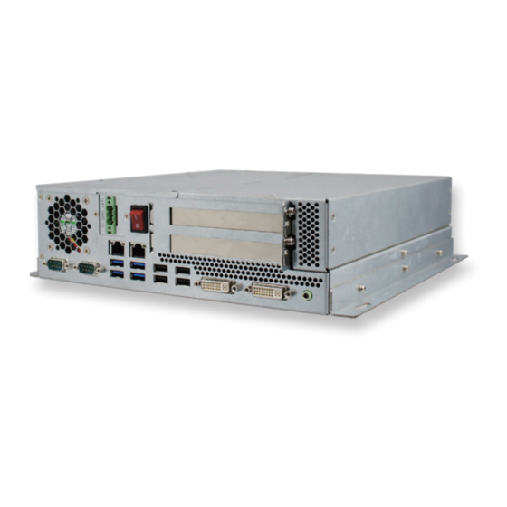
Page 14: Product I/O View & Introduction Of Specify Function
IBASE Technology Inc. 1.2.3 Product I/O view & Introduction of specify function Copyright © 2014 IBASE Technology Inc. All Rights Reserved. - Page 15 AMS200 User Manual...
-
Page 16: Exploded View Of The Ams200 Assembly
IBASE Technology Inc. 1.3 Exploded View of the AMS200 Assembly 1.3.1 Parts Description Part No. Description Part No. Description AMS200_base DIP PCBA, ABP-MB70 rocker sw_13.5x19_reset AMS200_bracket NUT-BT20 AMS200_cover brk AMS200_pci cover brk AMS200_HDD_asm Copyright © 2014 IBASE Technology Inc. All Rights Reserved. -
Page 17: Packing List
AMS200 User Manual CG-6F AMS200_DC-in_asm PCI expansion card_asm AMS200_side brk AMS200_L_asm ABP-ID45_asm PCIe card_asm SYS_FAN SYS_FAN AMS200_batt_asm AMS200_pci brk2 AMS200_pci brk1 ABP-IP702_asm SCREW-E2 SCREW-B30 NUTBOSS-S6 SCREW-B28A AMS200 cover label System label AMS200_HDD2_asm 1.4 Packing List Item No. Description Driver CD... -
Page 18: Chapter 2 Motherboard Introduction
25 x 27 mm package size BIOS Model AMI BIOS Memory Configuration Intel Ivy-Bridge mobile processors integrated memory ® controller DDRIII 1067/1333/1600 MHz - SO-DIMM [204-pin Horizontal type stacking] x 2 (Non-ECC) Copyright © 2014 IBASE Technology Inc. All Rights Reserved. - Page 19 AMS200 User Manual Max. Support Max. 16GB Onboard backup SRAM Edge I/O Display - Intel Ivy-Bridge mobile processor integrated Gfx, ® supports 2 independent displays, Direct X 11, OpenGL 3.1, Open CL 1.1 First DVI-I X 1 (thru Level shifter ASM1442)
- Page 20 Delay on for 2 seconds when main power is switched Maximum DC power wattage: 320W Connector: ATX 4-pin 2x2 connector x1 for DC power - Power consumption: 2x 12V, 8A Copyright © 2014 IBASE Technology Inc. All Rights Reserved.
-
Page 21: Board Dimensions
AMS200 User Manual 1x 5V, 10A 1x 3.3V, 10A Environmental Temperatur Operating: 0°C~60°C Storage: -20°C~70°C (-4°F~158°F) Humidity 5%~90% (non-condensing) Shock In operation 50 m/s2, 30 ms Storage/transport 250 m/s2, 6 ms Vibration In operation: 10 to 58Hz: 0.075mm, 58 to 500Hz: 9.8 m/s2 Storage/transport: 5 to 9 Hz: 3.5mm, 9 to 500Hz: 9.8 m/s2... -
Page 22: Setting The Jumpers
Contact your supplier if you have doubts about the best configuration for your needs. The following lists the connectors on ABP-MB70 and their respective functions. 2.4 Jumper Locations on ABP-MB70 Copyright © 2014 IBASE Technology Inc. All Rights Reserved. - Page 23 AMS200 User Manual JP1: Clear CMOS Contents Setting Function Pin 1-2 Normal Short/Closed Pin 2-3 Clear CMOS Short/Closed JP2: ATX or AT Power Selection Setting Function Pin 1-2 ATX Mode Short/Closed Pin 2-3 AT Mode Short/Closed...
- Page 24 IBASE Technology Inc. Connector Locations on ABP-MB70 Copyright © 2014 IBASE Technology Inc. All Rights Reserved.
- Page 25 AMS200 User Manual CN1, CN22: SATA3 Connector CN3: Interface to ABP-ID45 This connects to ABP-ID45 two seven-segment on daughter card BIOS need to support POST codes IBASE standard CN4: Gigabit LAN (82579V) + USB3 0/1, USB2 0/1 port CN5: Gigabit LAN (RTL8111E) + USB3 2/3, USB2 2/3 port...
- Page 26 A GROUND 1 A GROUND3 USB1, USB2: USB2 8/9/10/11 port J1: +24V Power Connector Pin # Signal Name Ground Ground +24V +24V J2: Battery 1/2AA Connector Pin # Signal Name Ground Copyright © 2014 IBASE Technology Inc. All Rights Reserved.
- Page 27 AMS200 User Manual J4, J5: HDD Power Connector Pin # Signal Name Ground Ground +12V J6: COM3, COM4 Serial Port (DF11 Connector) Signal Name Pin # Pin # Signal Name DSR1 DCD1 Data set ready Data carrier detect RTS1 RXD1...
- Page 28 J15: USB2 4/5 Port Connector (DF11 Connector) Signal Signal Name Name Ground Ground J16: Flash Descriptor Security Override (Factory use only) Flash Descriptor Setting Security Override Open Disabled (Default) Close Enabled Copyright © 2014 IBASE Technology Inc. All Rights Reserved.
- Page 29 AMS200 User Manual J19: Audio Connector (DF11 Connector) Signal Name Pin # Pin # Signal Name LINEOUT_R LINEOUT_L Ground JD_FRONT LINEIN_R LINEIN Ground JD_LINEIN MIC-In MIC_L Ground JD_MIC1 CPU_FAN1: CPU Fan Power Connector Pin # Signal Name Ground +12V Rotation...
- Page 30 Signal Name Ground +12V Rotation detection SYS_FAN2: System Fan Power Connector Pin # Signal Name Ground +12V PCIE1: PCIEx16 Slot (Including PCI-E(x16) signal) PCIE2: PCIEx16 Slot (Including PCI-E(x4) & PCI signals) Copyright © 2014 IBASE Technology Inc. All Rights Reserved.
-
Page 31: Chapter 3 Bios Setup
AMS200 User Manual CHAPTER 3 BIOS SETUP This chapter describes the different settings available in the AMI BIOS that comes with the board. The topics covered in this chapter are as follows: BIOS Introduction The BIOS (Basic Input/Output System) installed in your computer system’s ROM supports Intel processors. - Page 32 Aptio Setup Utility Advanced Main Chipset Boot Security Save & Exit ► PCI Subsystem Settings ► ACPI Settings ► Wake up event setting ► Trusted Computing ► CPU Configuration Copyright © 2014 IBASE Technology Inc. All Rights Reserved.
- Page 33 AMS200 User Manual ► SATA Configuration ► Shutdown Temperature Configuration → ← Select Screen ► USB Configuration ↑↓ Select Item ► F81866 Super IO Configuration Enter: Select ► F81866 H/W Monitor Change Field ► CPU PPM Configuration F1: General Help...
- Page 34 WARNING: Enabling ASPM may cause Disabled F3: Optimized Default PCI-E devices to fail F4: Save ESC: Exit Extended Synch Disabled Link Training Retry Link Training Timeout (uS) Unpopulated Links Keep Link ON Copyright © 2014 IBASE Technology Inc. All Rights Reserved.
- Page 35 AMS200 User Manual Relaxed Ordering Enables or disables PCI Express Device Relaxed Ordering. Extended Tag If ENABLED allows device to use 8-bit Tag field as a requester. No Snoop Enables or disables PCI Express Device No Snoop option. Maximum Payload Set Maximum Payload of PCI Express Device or allow System BIOS to select the value.
- Page 36 Select ACPI sleep state the system will enter, when the SUSPEND button is pressed. Lock Legacy Resources Enabled or Disabled Lock of Legacy Resources. S3 Video Repost Enable or disable S3 Video Repost. Copyright © 2014 IBASE Technology Inc. All Rights Reserved.
- Page 37 AMS200 User Manual Wake up event settings Aptio Setup Utility Advanced Main Chipset Boot Security Save & Exit Wake system with Fixed Time Disabled Wake up hour Wake up minute Wake up second → ← Select Screen ↑↓ Select Item...
- Page 38 Enabled for Windows XP and Linux (OS optimized for Hyper-Threading Technology) and Disabled for other OS (OS not optimized for Hyper-Threading Technology). When Disabled, only one thread per enabled core is enabled. Active Processor Cores Copyright © 2014 IBASE Technology Inc. All Rights Reserved.
- Page 39 AMS200 User Manual Number of cores to enable in each processor package. Limit CPUID Maximum Disabled for Windows XP. Execute Disable Bit XD can prevent certain classes of malicious buffer overflow attacks when combined with a supporting OS (Windows Server 2003 SP1, Windows XP SP2, SuSE Linux 9.2, Re33dHat Enterprise 3 Update 3.)
- Page 40 APCI Shutdown Temperature Disabled ↑↓ Select Item Enter: Select Change Field F1: General Help F2: Previous Values F3: Optimized Default F4: Save ESC: Exit ACPI Shutdown Temperature The default setting is Disabled. Copyright © 2014 IBASE Technology Inc. All Rights Reserved.
- Page 41 AMS200 User Manual USB Configuration Aptio Setup Utility Advanced Main Chipset Boot Security Save & Exit USB Configuration USB Devices: 2 Hubs Legacy USB Support Enabled USB3.0 Support Enabled → ← Select Screen XHCI Hand-off Enabled ↑↓ Select Item EHCI Hand-off...
- Page 42 ► Serial Port 1 Configuration F1: General Help ► Serial Port 2 Configuration F2: Previous Values ► Serial Port 3 Configuration F3: Optimized Default F4: Save ESC: Exit ►Parallel Port Configuration Copyright © 2014 IBASE Technology Inc. All Rights Reserved.
- Page 43 AMS200 User Manual Serial Port Configuration Set Parameters of Serial Ports. User can Enable/Disable the serial port and Select an optimal settings for the Super IO Device. Parallel Port Configuration Set Parameters of Parallel Port(LPT/LPTE) F81866 H/W Monitor Aptio Setup Utility...
- Page 44 Fan1/Fan2 Smart Fan Control This field enables or disables the smart fan feature. At a certain temperature, the fan starts turning. Once the temperature drops to a certain level, it stops turning again. Copyright © 2014 IBASE Technology Inc. All Rights Reserved.
- Page 45 AMS200 User Manual CPU PPM Configuration Aptio Setup Utility Advanced Main Chipset Boot Security Save & Exit CPU PPM Configuration EIST Enabled Turbo Mode Enabled → ← Select Screen ↑↓ Select Item Enter: Select Change Field F1: General Help F2: Previous Values...
- Page 46 ► PCH Azalia Configuration PCH LAN Controller Enabled Wake on LAN Enabled High Precision Event Timer Configuration → ← High Precision Timer Enabled Select Screen ↑↓ Select Item SLP_S4 Assertion Width 4-5 Seconds Copyright © 2014 IBASE Technology Inc. All Rights Reserved.
- Page 47 AMS200 User Manual Enter: Select Change Field F1: General Help F2: Previous Values F3: Optimized Default F4: Save ESC: Exit PCH LAN Controller Enable or disable onboard NIC. Wake on LAN Enable or disable integrated LAN to wake the system. (The Wake On LAN cannot be disabled if ME is on at Sx state.)
- Page 48 The control of Active State Power Management on both NB side and SB side of the DMI link. PCIe-USB Glitch W/A PCIe-USB Glitch W/A for bad USB device(s) connected behind PCIE/PEG port. Copyright © 2014 IBASE Technology Inc. All Rights Reserved.
- Page 49 AMS200 User Manual USB Configuration Chipset Main Advanced Boot Security Save & Exit USB Configuration EHCI1 Enabled EHCI2 Enabled USB Ports Per-Port Disable Control Disabled → ← Select Screen ↑↓ Select Item Enter: Select Change Field F1: General Help F2: Previous Values...
- Page 50 CHAP Device (B0:D7:F0) Disabled ↑↓ Select Item Thermal Device (B0:D4:F0) Disabled Enter: Select Enable NB CRID Disabled Change Field BDAT ACPI Table Support Disabled F1: General Help C-State Pre-Wake Enabled F2: Previous Values Copyright © 2014 IBASE Technology Inc. All Rights Reserved.
- Page 51 AMS200 User Manual F3: Optimized Default ► Graphics Configuration F4: Save ESC: Exit ► Memory Configuration VT-d Check to enable VT-d function on MCH. Enable NB CRID Enable or disable NB CRID WorkAround. C-State Pre-Wake Controls C-State Pre-Wake feature for ARAT, in SSKPD[57].
- Page 52 2048 MB (DDR3) → ← Select Screen DIMM#1 Not Present ↑↓ Select Item DIMM#2 2048 MB (DDR3) Enter: Select DIMM#3 Not Present Change Field CAS Latency (tCL) F1: General Help Minimum delay time Copyright © 2014 IBASE Technology Inc. All Rights Reserved.
- Page 53 AMS200 User Manual F2: Previous Values CAS to RAS (tRCDmin) F3: Optimized Default Row Precharge (tRPmin) F4: Save ESC: Exit Active to Precharge (tRASmin) Boot Settings This section allows you to configure the boot settings. Aptio Setup Utility Boot Main...
- Page 54 Launch PXE OpROM policy Do not launch Launch Storage OpROM policy Legacy only Launch Video OpROM policy Legacy only → ← Select Screen ↑↓ Select Item Other PCI device ROM priority Legacy OpROM Copyright © 2014 IBASE Technology Inc. All Rights Reserved.
- Page 55 AMS200 User Manual Enter: Select Change Field F1: General Help F2: Previous Values F3: Optimized Default F4: Save ESC: Exit Boot option filter This option controls what devices system can boot to. Launch PXE OpROM policy Controls the execution of UEFI and Legacy PXE OpROM.
- Page 56 Change Field Save Changes F1: General Help Discard Changes F2: Previous Values F3: Optimized Default Restore Defaults F4: Save ESC: Exit Save as User Defaults Restore User Defaults Save Changes and Exit Copyright © 2014 IBASE Technology Inc. All Rights Reserved.
- Page 57 AMS200 User Manual Exit system setup after saving the changes. Discard Changes and Exit Exit system setup without saving any changes. Save Changes and Reset Reset the system after saving the changes. Discard Changes and Reset Reset system setup without saving any changes.
-
Page 58: Chapter 4 Drivers Installation
INF support for Intel chipset components. Follow the instructions below to complete the installation. 1. Insert the CD that comes with the board. Click Intel and then Intel(R) 7 Series Chipset Drivers. 2. Click Intel(R) Chipset Software Installation Utility. Copyright © 2014 IBASE Technology Inc. All Rights Reserved. - Page 59 AMS200 User Manual 3. When the Welcome screen to the Intel® Chipset Device Software appears, click Next to continue. 4. Click Yes to accept the software license agreement and proceed with the installation process. 5. On the Readme File Information screen, click Next to continue the installation.
-
Page 60: Vga Drivers Installation
1. Insert the CD that comes with the board. Click Intel and then Intel(R) Q7 Series Chipset Drivers. 2. Click Intel(R) Q77 Chipset Family Graphics Driver. 3. When the Welcome screen appears, click Next to continue. Copyright © 2014 IBASE Technology Inc. All Rights Reserved. -
Page 61: Realtek Hd Audio Driver Installation
AMS200 User Manual 4. Click Yes to to agree with the license agreement and continue the installation. 5. On the Readme File Information screen, click Next to continue the installation of the Intel® Graphics Media Accelerator Driver. 6. On Setup Progress screen, click Next to continue. -
Page 62: Lan Drivers Installation
4.4 LAN Drivers Installation 1. Insert the CD that comes with the board. Click Intel and then Intel(R) Q7 Series Chipset Drivers. 2. Click Intel(R) PRO LAN Network Driver. Copyright © 2014 IBASE Technology Inc. All Rights Reserved. - Page 63 AMS200 User Manual 3. Click Install Drivers and Software. 4. When the Welcome screen appears, click Next. 5. Click Next to to agree with the license agreement. 6. Click the checkbox for Drivers in the Setup Options screen to select it and click...
-
Page 64: Realtek Lan Controller Drivers Installation
1. Insert the CD that comes with the board. Click Intel, then LAN Card, and then Realtek Lan Controller Drivers. 2. Click Realtek RTL8111E LAN Drivers. 3.When the welcome screen to InstallShield Wizard appears, click Next to start the installation. Copyright © 2014 IBASE Technology Inc. All Rights Reserved. - Page 65 AMS200 User Manual 4.When the InstallShieldWizard has finished installing the Realtek LAN drivers, click Finish.
-
Page 66: Appendix
Choose fasteners that are rated either ”Medium Duty“ or ”Heavy Duty.“ To assure proper fastener selection and installation, follow the fastener manufacturer’s Copyright © 2014 IBASE Technology Inc. All Rights Reserved. -
Page 67: Wall Mounting Requirements
AMS200 User Manual recommendations. Wall Mounting Requirements Note: Before mounting the system on wall, ensure that you are following all applicable building and electric codes. When mounting, ensure that you have enough room for power and signal cable routing. And have good ventilation for power adapter. The method of mounting must be able to support weight of the CSB110-902 plus the suspend weight of all the cables to be attached to the system.
Need help?
Do you have a question about the AMS200 and is the answer not in the manual?
Questions and answers