Table of Contents
Advertisement
Quick Links
Getting started with the AEK-POW-BMS63EN battery management system
Introduction
In a multicell battery pack, placing cells in series augments the possibilities of cell imbalance, which equates to a slower but
persistent degradation of the battery.
There are always slight differences in the state of charge (SOC), self-discharge rate, capacity, impedance, and temperature
characteristics, even for cells of the same model from the same manufacturer and even from the same batch of production.
These differences can lead to a divergence in a battery cell voltage over time. Cells with lower capacity or higher internal
impedance tend to have higher voltage than the rest of the series cells at full charge. These cells are weakened further by
continuous overcharge cycles. The higher voltage of weak cells at charge completion causes accelerated capacity degradation.
On the other hand, in discharge, the weak cells tend to have lower voltage than the other cells, due to either higher internal
resistance or the faster rate of discharge that results from their smaller capacity. This means that if any of the weak cells hits the
cell undervoltage-protection limit while the pack voltage is still sufficient to power the system, the full capacity of the battery is
not used.
One of the emerging technologies for enhancing battery safety and extending battery life is advanced cell balancing. Since
new cell balancing technologies track the amount of balancing needed by individual cells, the usable life of battery packs is
increased, and overall battery safety is enhanced.
A battery management system (BMS) can manage battery cells, enhancing their safety and duration.
A BMS combines hardware and software to monitor and send acquired data to a dedicated device to protect the battery from
overload or over discharge, lengthening its life cycle.
In the earlier BMSs, the SOC estimation was based only on the voltage reading.
Nowadays, instead, this estimation is based on Kalman filters, which provide more accurate data on the SOC by reading the
voltage, the current, and the temperature of battery cells.
The modern BMS includes functions such as cell monitoring, balancing, safety and protection of the batteries, the state of
charge estimation and thermal management:
•
Cell monitoring: this function is based on the acquisition of the current, the voltage, and the temperature of each cell of
the battery pack.
•
Cell balancing: consists of distributing the energy and maintaining the SOC of the cells at a similar level. There are two
different types of balancing: active and passive. Active balancing consists of transferring the exceeding energy of cells
with a higher SOC to cells with a lower SOC to reach the same level. Passive balancing dissipates the exceeding energy
of cells with a higher SOC, generating heat. Cell balancing is a key function to maintain the battery capacity and lengthen
its duration.
•
Battery safety and protection: a BMS ensures that the battery works in safe conditions for the users and the battery itself.
•
State of charge (SOC) and state of health (SOH): an accurate SOC estimation is necessary to lengthen the battery life
cycle, prevent battery damage, and ensure efficiency and accurate calculations of the SOH and cell balancing.
Our
AEK-POW-BMS63EN
is a battery management system (BMS) evaluation board that can handle from 1 to 31 Li-ion battery
nodes. Each battery node manages from 4 to 14 battery cells, for a voltage range between 48 V and 800 V.
The board is based on the L9963E, which is designed for operation in both hybrid (HE) and full electric (BE) vehicles using
lithium battery packs, but its use can be extended to other Transportation and Industrial applications.
The L9963E is an ASIL-D, AEC-Q1000 qualified device, compliant with ISO26262.
The main activity of the L9963E is monitoring cells and battery node status through stack voltage measurement, cell voltage
measurement, temperature measurement, and coulomb counting. Measurement and diagnostic tasks can be executed either on
demand or periodically, with a programmable cycle interval. Measurement data are available for an external microcontroller to
perform charge balancing and to compute the state of charge (SOC) and the state of health (SOH).
The AEK-POW-BMS63EN can measure 5 values of temperature through 5 GPIOs (which can be configured as analog inputs to
connect NTCs).
UM3185 - Rev 1 - May 2023
For further information contact your local STMicroelectronics sales office.
(BMS) evaluation board based on the L9963E
UM3185
User manual
www.st.com
Advertisement
Table of Contents

Subscribe to Our Youtube Channel
Related Manuals for STMicroelectronics AEK-POW-BMS63EN


Summary of Contents for STMicroelectronics AEK-POW-BMS63EN
- Page 1 Measurement data are available for an external microcontroller to perform charge balancing and to compute the state of charge (SOC) and the state of health (SOH). The AEK-POW-BMS63EN can measure 5 values of temperature through 5 GPIOs (which can be configured as analog inputs to connect NTCs).
-
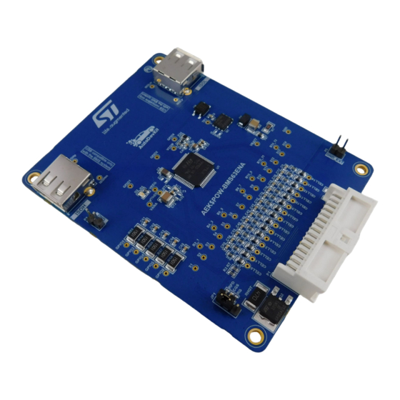
Page 2: Figure 1. Aek-Pow-Bms63En Evaluation Board
The communication is performed at two different speeds: high speed of 2.66 Mbps and low speed of 333 kbps. Note: The AEK-POW-BMS63EN evaluation board is designed for R&D laboratory use only; it is not intended for field use in vehicles. -
Page 3: Hardware Overview
UM3185 Hardware overview Hardware overview Main components ISOH port to connect the board to the AEK-COM-ISOSPI1 ISOL port to connect the board to another AEK-POW-BMS63EN in a daisy chain L9963E GPIOs for external NTC connection Hot plug protection Balancing resistors Connector for the battery pack Figure 2. -
Page 4: Voltage Operating Range
The power supply range is from 9.6 V to a maximum of 64 V. 1.3.1 Linear regulators The AEK-POW-BMS63EN features several linear voltage regulators, which are switched on according to a specific sequence at power-up (see Figure 11. Finite state machine of the voltage conversion routine). -
Page 5: Simplified State Machine
UM3185 Voltage operating range 1.3.2 Simplified state machine Figure 3. State machine 1.3.2.1 Reset and sleep states When the standby logic is reset, all registers on the device are in the reset state. The battery voltage is still under threshold. No operation is possible during this state. The sleep state is reached: •... -
Page 6: Figure 4. Daisy Chain Addressing Procedure
This procedure is performed through the “StartUpWakeUp” function, which configures the AEK-COM-ISOSPI1 and assigns an ID to each AEK-POW-BMS63EN of the chain. IDs are sequentially assigned to all the BMS included in the system: ID no. 1 is assigned to the first BMS in the chain, ID no. -
Page 7: Figure 5. Addressing Procedure Example
UM3185 Voltage operating range Figure 5. Addressing procedure example To determine if the addressing procedure has been successful, check the D2 LED on the BMS. If it remains always on, it means that the procedure has been correctly executed and each BMS has its own ID. Only if you unplug the connector, the BMS loses their ID. - Page 8 UM3185 Voltage operating range • A wakeup signal on communication or fault line can force the chip to stop balancing and then go back to the normal state. • An external fault must bring the device to the normal state and stop the balancing. •...
-
Page 9: Bms Topologies
BMS topologies BMS topologies The AEK-POW-BMS63EN can work in two different daisy chain topologies: centralized and dual access ring. To build these two configurations, we used the AEK-COM-ISOSPI, which allows converting SPI signals in isolated SPI signals, thereby reducing the number of necessary wires from 4 to 2 and implementing differential communication for higher noise immunity. -
Page 10: Figure 7. Centralized Bms Diagram
UM3185 Centralized configuration Figure 7. Centralized BMS diagram Figure 8. Example of centralized BMS with AEK-COM-ISOSPI1 and AEK-MCU-C4MLIT1 UM3185 - Rev 1 page 10/59... -
Page 11: Dual Access Ring Configuration
UM3185 Dual access ring configuration Dual access ring configuration A dual access ring configuration is realized by adding another transceiver that makes the communication bidirectional. The secondary ring is used as a backup in case the primary ring fails. Data moves in opposite directions around the rings, and each ring remains independent of the other unless the primary ring fails. -
Page 12: Voltage Conversion Routine
UM3185 Voltage conversion routine Voltage conversion routine L9963E implements a flexible voltage conversion routine, whose main goals are: • Providing on-demand information about the cell voltage, the stack voltage, and the cell temperature. • Providing on-demand diagnostic information about device functionality. •... -
Page 13: Figure 11. Finite State Machine Of The Voltage Conversion Routine
UM3185 Voltage conversion routine Figure 11. Finite state machine of the voltage conversion routine SOC = state of conversion To start on-demand conversions, the user must set SOC = 1 in the ADCV_CONV register: in case the coulomb counting routine is enabled, every time an on-demand voltage conversion is requested by setting SOC = 1, the actual conversion start is delayed until the first useful current conversion takes place. -
Page 14: Coulomb Counting Routine
UM3185 Coulomb counting routine Coulomb counting routine The coulomb counting routine is performed to evaluate the charge injected/subtracted during vehicle operation. To enable it, the CoulombCounter_en bit must be set to 1. Disabling the coulomb counter by setting CoulombCounter_en to 0 does not reset the accumulator (CoulombCounter_msb, CoulombCounter_lsb) and sample counter (CoulombCntTime) registers. -
Page 15: Safety And Diagnostic Features
UM3185 Safety and diagnostic features Safety and diagnostic features The L9963E provides an extended set of safety mechanisms to reach the required ASIL standard. It monitors potentially damaging conditions for the battery pack. Cell UV/OV diagnostic It is possible to select the value for the overvoltage threshold as well as for the undervoltage threshold of the cells. This diagnostic feature is completed by analyzing, inside the logic block, the digital information provided by the voltage measurement ADCs. -
Page 16: Cell Open With Adc_Cross_Check = 1
UM3185 PCB open diagnostic • RLPF (low pass filter resistor) degradation: diagnostic has been implemented to guarantee that low pass filter resistor in series to the Cx pin is below the critical limit RLPF_OPEN: – On odd cells, RLPF degradation will cause the assertion of the corresponding CELLx_OPEN flag. –... -
Page 17: Fault Condition
UM3185 Fault condition Fault condition Figure 12. Fault LED on the AEK-COM-ISOSPI1 The fault LED on the AEK-COM-ISOSPI1 is related to the state of all the BMS nodes in the daisy chain. If an undervoltage, overvoltage, overcurrent, or overtemperature occurs on any cell of a BMS, a fault condition is detected. -
Page 18: Figure 14. Aek_Pow_Bms63En_Init() Definition
UM3185 Fault condition Figure 14. AEK_POW_BMS63EN_Init() definition AEK_POW_BMS3EN_Init() is located in the driver lib of the file component (AEK_POW_BMS3EN_id.c). Figure 15. AEK_POW_BMS63EN_Init() location In the application AEK_POW_BMS3EN_Appl.c file, there is also a function that reads the current and temperature. UM3185 - Rev 1 page 18/59... -
Page 19: Figure 16. Functions For Current And Temperature Reading
UM3185 Fault condition Figure 16. Functions for current and temperature reading Figure 17. Resistor value to modify UM3185 - Rev 1 page 19/59... -
Page 20: Cell Balancing
UM3185 Cell balancing Cell balancing In the L9963E, the Sx and Bx_x-1 pins are used to balance the charge of the cells by discharging the ones with a higher SOC. Balancing can be performed either with external resistors or internal MOSFETs. Cell balance drivers are powered by VBAT stack voltage. -
Page 21: Methods For Soc Estimation
UM3185 Methods for SOC estimation Methods for SOC estimation The state of charge (SOC) of a cell indicates the energy stored by a cell, defined as the ratio of the charge quantity of a cell in a given moment and its total capacity. The traditional calculation method is the coulomb counting. - Page 22 UM3185 Methods for SOC estimation dV 1 − C 1 SOC, T R 1 SOC, T ∙ C 1 SOC, T V t = V 0 SOC, T − iR 0 − V 1 Where: • SOC is the state of charge •...
-
Page 23: Autodevkit Ecosystem
The doc folder contains the doxygen documentation. The lib folder contains the component header and source files. Software component architecture (AEK-POW-BMS63EN component RLA) The following image shows the architecture of the software components created for the AEK-POW-BMS63EN evaluation board, which consists of the following layers: •... -
Page 24: Aek-Pow-Bms63En In Autodevkit
AEK-POW-BMS63EN in AutoDevKit 9.3.1 Centralized configuration example This example is an application for the AEK-POW-BMS63EN in a centralized daisy chain topology using the AEK-MCU-C4MLIT1 as the microcontroller board. To recreate this scenario, follow the procedure below. Step 1. Create a new SPC5-STUDIO application for the SPC58EC series microcontroller and add the following components: –... -
Page 25: Figure 23. Adding Aek-Com-Isospi1 Component Rla
UM3185 AEK-POW-BMS63EN in AutoDevKit Step 2. Add the following additional components: – AEK-COM-ISOSPI1 Component RLA Figure 23. Adding AEK-COM-ISOSPI1 Component RLA Step 3. Select [AEK-COM-ISOSPI1 Component RLA] to open the [Application Configuration] window. Figure 24. Selecting AEK-COM-ISOSPI1 Component RLA UM3185 - Rev 1... -
Page 26: Figure 25. Adding A New Element
UM3185 AEK-POW-BMS63EN in AutoDevKit Step 4. Click on [+] to add a new element to the board list. Figure 25. Adding a new element Step 5. Double-click on the newly added element to configure the board. Figure 26. AEK-COM-ISOPI1 configuration... -
Page 27: Figure 27. Aek-Com-Isopi1 Scenario Two Configurations
UM3185 AEK-POW-BMS63EN in AutoDevKit Step 6. Configure parameters – Select scenario [two] – Select [DSPI] protocol number and [CS] chip select – Select the [cfg] configuration as [micro] – Select [TxAmp] as [not amplified] – Select [ISOFreq] as [333 KHz] –... -
Page 28: Figure 29. Adding Aek-Pow-Bms63En Component Rla
Step 8. Add the following additional components: – AEK-POW-BMS63EN Component RLA Figure 29. Adding AEK-POW-BMS63EN Component RLA Step 9. Select [AEK-POW-BMS63EN Component RLA] to open the [Application Configuration] window. Figure 30. Selecting AEK-POW-BMS63EN Component RLA UM3185 - Rev 1 page 28/59... -
Page 29: Figure 31. Isospi Configuration
UM3185 AEK-POW-BMS63EN in AutoDevKit Step 10. Select ISOSPI configuration settings: – Select [Daisy Chain Topology] as [Centralized]. – Select the already allocated in the [ISOSPI Transceiver Centralized] field. – Select [ISOSPI Frequency Mode] as [ISOFREQHigh]. Figure 31. ISOSPI configuration UM3185 - Rev 1... -
Page 30: Figure 32. Component Configuration
UM3185 AEK-POW-BMS63EN in AutoDevKit Step 11. Click on AEK_POW_BMS63EN list item to configure each component allocated. Figure 32. Component configuration Step 12. Configure Over/Under Voltage Battery Thresholds. Figure 33. Over/undervoltage battery threshold configuration Step 13. Configure Over/Under Voltage Cell Thresholds. -
Page 31: Figure 36. Coulomb Counting And Adc Filter Soc Configuration
UM3185 AEK-POW-BMS63EN in AutoDevKit Step 15. Configure Coulomb counting to Enable Current measurement and ADC Filter SOC timing. Figure 36. Coulomb counting and ADC filter SOC configuration Step 16. Configure the GPIOs: – Configure Conversion configuration for the analog input GPIO. -
Page 32: Figure 39. Vtref Configuration
UM3185 AEK-POW-BMS63EN in AutoDevKit Step 18. Check that the VTref option is always enabled. Figure 39. VTref configuration Step 19. Include AEK_POW_BMS63EN_id.h in your main application and write your application code. Step 20. Click on [Board View] to display the hardware connection between the AEK-MCU-C4MLIT1 board and the AEK-COM-ISOSP1. -
Page 33: Dual Access Ring Configuration Example
Step 23. Switch on the AEK-MCU-C4MLIT1 to start your BMS application. Note: If you want to define a centralized daisy chain configuration with more than one AEK-POW-BMS63EN, it is necessary to allocate more than one component in step 11. 9.3.2... -
Page 34: Centralized Application
This application is based on the SPC58EC microcontroller and can estimate the SOC of 3x14 cells (in our case, the battery used are INR 18650 MJ1 by LG) connected with 3 AEK-POW-BMS63EN evaluation boards. The results of SOC estimation, cell voltage, NTC temperatures, and current are printed via a serial port with a speed rate of 115200 bps. - Page 35 UM3185 Available demos for AEK-POW-BMS63EN sprintf(message," \n"); sd_lld_write(&SD5, (uint8_t *)message, (uint16_t)(sizeof(message)/sizeof(message[0]))); //Printing Voltage for(cell_idx = AEK_POW_BMS63EN_CELL1; cell_idx <= AEK_POW_BMS63EN_CELL14; cell_idx ++){ sprintf(message, "V%.2d:%.3f ", cell_idx+1, AEK_POW_BMS63EN_BatteryModule.AEK_POW_BMS63EN_Pa ck_CellVoltage[cell_idx]); sd_lld_write(&SD5, (uint8_t *)message, (uint16_t)(sizeof(message)/sizeof(message[0]))); sprintf(message," \n"); sd_lld_write(&SD5, (uint8_t *)message, (uint16_t)(sizeof(message)/sizeof(message[0]))); //Printing Current sprintf(message, "C:%.4f \n", AEK_POW_BMS63EN_BatteryModule.AEK_POW_BMS63EN_Pack_Current);...
-
Page 36: Dual Ring Application
This application is based on the SPC58EC microcontroller and can estimate the SOC of 1x14 cells (in our case, the battery used are INR 18650 MJ1 by LG) connected with 2 AEK-POW-BMS63EN evaluation boards. The results of SOC estimation, cell voltage, NTC temperatures, and current are printed via serial protocol with a speed rate of 115200 bps. -
Page 37: Single Centralized Application
This application is based on the SPC58EC microcontroller and can estimate the SOC of 14 cells in a single BMS node (in our case, the battery used are INR 18650 MJ1 by LG) connected with an AEK-POW-BMS63EN evaluation board. - Page 38 Available demos for AEK-POW-BMS63EN Find below the main code for the SPC58EC – AEK_POW_BMS63EN_SOC_Estimation_Single application for discovery demo: * Copyright © 2022 STMicroelectronics - All Rights Reserved * License terms: STMicroelectronics Proprietary in accordance with licensing * terms SLA0089 at www.st.com.
- Page 39 UM3185 Available demos for AEK-POW-BMS63EN extern uint8_t __heap_base__; extern uint8_t __heap_end__; static uint8_t *p=&__heap_base__; static uint8_t *newp; newp = p+ incr; if(newp> &__heap_end__) return (void*)-1; return p =newp; int main(void) { componentsInit(); irqIsrEnable(); wkpu_lld_start(&WKPUD1, &wkpu_config_wkpu_cfg); AEK_POW_BMS63EN_init(); runCore0(); AEK_POW_BMS63EN_Start_Mgn_exec(); while (1) { This application enables two cores: •...
-
Page 40: Available Apis
UM3185 Available APIs Available APIs The APIs listed in the following tables are declared in the AEK_POW_BMS63EN_id.h file. Table 1. General purpose APIs for the AEK-POW-BMS63EN Key API name Description AEK_POW_BMS63EN_Init (void) Driver instance(s) initialization. AEK_POW_BMS63EN_ParameterConfiguration (void) Driver instance(s) parameter configuration. -
Page 41: Table 4. Gpio 9, 3 Configuration Apis For The Aek-Pow-Bms63En
AEK_POW_BMS63EN_StopCellBalancing (unsigned Stops the balancing on the enabled AEK_POW_BMS63EN_devnum) cells of a device. Table 4. GPIO 9, 3 configuration APIs for the AEK-POW-BMS63EN Key API name Description AEK_POW_BMS63EN_ConfigGPIO (unsigned AEK_POW_BMS63EN_devnum, AEK_POW_BMS63EN_gpio_t Configures the GPIO 3 - 9. -
Page 42: Table 5. Other Apis For The Aek-Pow-Bms63En
Checks Enabled Cell. AEK_POW_BMS63EN_devnum, AEK_POW_BMS63EN_cell_id_t cell_idx AEK_POW_BMS63EN_SetOvercurrentThreshold (unsigned AEK_POW_BMS63EN_devnum, uint16_t Rshunt, float Sets OverCurrent Threshold. current_th_A) Table 5. Other APIs for the AEK-POW-BMS63EN Key API name Description AEK_POW_BMS63EN_ObjectInit Initializes the standard part of a (AEK_POW_BMS63EN_Driver *AEK_POW_BMS63ENp) AEK_POW_BMS63EN_Driver structure. AEK_POW_BMS63EN_Start (AEK_POW_BMS63EN_Driver... - Page 43 UM3185 Available APIs Key API name Description AEK_POW_BMS63EN_DualRingTX_reverse (void) Reverse TX in dual ring mode. For further details on the APIs, refer to the doxygen documentation under the doc folder (see Component folder structure). UM3185 - Rev 1 page 43/59...
-
Page 44: Waveforms
The following waveform shows the time trend of the battery pack voltage (defined by 14 cells connected to an AEK-POW-BMS63EN in a single centralized configuration) with an active load of 1 A. The x axis shows the time (in hours). The y axis shows the battery pack voltage in Volts and the load current. -
Page 45: Process Timing
UM3185 Process timing The following waveform shows the time trend of the voltages of the 14 cells connected to an AEK-POW- BMS63EN in a single centralized configuration, when balancing is active. The x axis shows the time (in hours). The y axis shows the voltages of the 14 cells in Volts. Figure 45. -
Page 46: Figure 46. Voltage Estimation Waveform
UM3185 Process timing Figure 46. Voltage estimation waveform Figure 47. NTC temperature estimation waveform UM3185 - Rev 1 page 46/59... -
Page 47: Figure 48. Soc Estimation Waveform
UM3185 Process timing Figure 48. SOC estimation waveform Figure 49. Fault estimation waveform UM3185 - Rev 1 page 47/59... -
Page 48: Schematic Diagrams
UM3185 Schematic diagrams Schematic diagrams Figure 50. AEK-POW-BMS63EN schematic diagram VBATT VBAT_UP STL8N10LF3 VBAT_CELL VBAT_CELL MPZ2012S102ATD25 RMREG 47nF N.M. 4.7uF VBAT_CELL 2.2uF 100nF 100pF 100nF 100K GND_EXT 100nF N.M. L9963E N.M. VREG VBAT VREG VREG CELL14 VCOM VTREF VCOM VCOM... -
Page 49: Bill Of Materials
UM3185 Bill of materials Bill of materials Table 7. Manufacture Item Q.ty Ref. Part / Value Description Order code C1, C8, C15, C19, C21, C29, C31, C33, C40, 0603 - 50V - X7R 47nF 885012206093 C42, C45, C48, Class II C50, C57, C59, C71, C75, C76 1206 - 50V - X7R... - Page 50 UM3185 Bill of materials Manufacture Item Q.ty Ref. Part / Value Description Order code 0805 - Led Green - Green 150080GS75000 3.2V SZMM3Z4V7T1 4.7V Zener Voltage Onsemi SZMM3Z4V7T1G Regulators, 300mW FB1, FB2, FB3, FB4, FB5, FB6, Ferrite Beads FB7, FB8, FB9, Multi-Layer Power FB10, FB11, 1K@100MHz...
- Page 51 UM3185 Bill of materials Manufacture Item Q.ty Ref. Part / Value Description Order code R15, R18, R25, 60.4 0603 - ±1% - 0.1W Panasonic ERJ3EKF60R4V R20, R43 0603 - ±1% - 0.2W Panasonic ERJP03F1002V R30, R36, R42 6.2K 0805 - ±1% - 0.5W Panasonic ERJP06F6201V 0603 - ±1% - 0.2W...
-
Page 52: Board Versions
AEK-POW-BMS63EN versions Finished good Schematic diagrams Bill of materials AEK$POW-BMS63ENA AEK-POW-BMS63EN schematic diagrams AEK-POW-BMS63EN bill of materials 1. This code identifies the AEK-POW-BMS63EN evaluation board first version. It is printed on the board PCB. UM3185 - Rev 1 page 52/59... -
Page 53: Regulatory Compliance Information
UM3185 Regulatory compliance information Regulatory compliance information Notice for US Federal Communication Commission (FCC) For evaluation only; not FCC approved for resale FCC NOTICE - This kit is designed to allow: (1) Product developers to evaluate electronic components, circuitry, or software associated with the kit to determine whether to incorporate such items in a finished product and (2) Software developers to write software applications for use with the end product. -
Page 54: Revision History
UM3185 Revision history Table 9. Document revision history Date Version Changes 16-May-2023 Initial release. UM3185 - Rev 1 page 54/59... -
Page 55: Table Of Contents
Available demos for AEK-POW-BMS63EN ........ - Page 56 UM3185 Contents 9.4.2 Dual ring application (SPC58EC – AEK_POW_BMS63EN_SOC_Estimation_DualRing application for discovery demo)..........36 9.4.3 Single centralized...
- Page 57 Selecting AEK-POW-BMS63EN Component RLA ........
- Page 58 Application-oriented APIs for the AEK-POW-BMS63EN ........
- Page 59 IMPORTANT NOTICE – READ CAREFULLY STMicroelectronics NV and its subsidiaries (“ST”) reserve the right to make changes, corrections, enhancements, modifications, and improvements to ST products and/or to this document at any time without notice. Purchasers should obtain the latest relevant information on ST products before placing orders. ST products are sold pursuant to ST’s terms and conditions of sale in place at the time of order acknowledgment.
Need help?
Do you have a question about the AEK-POW-BMS63EN and is the answer not in the manual?
Questions and answers