Sign In
Upload
Manuals
Brands
STMicroelectronics Manuals
Motherboard
AEK-POW-BMS63EN
STMicroelectronics AEK-POW-BMS63EN Manuals
Manuals and User Guides for STMicroelectronics AEK-POW-BMS63EN. We have
1
STMicroelectronics AEK-POW-BMS63EN manual available for free PDF download: User Manual
STMicroelectronics AEK-POW-BMS63EN User Manual (59 pages)
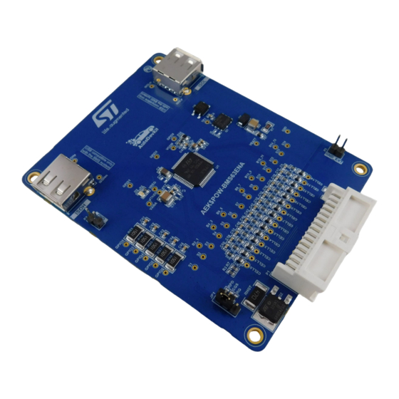
Battery Management System (BMS) Evaluation Board Based on the L9963E
Brand:
STMicroelectronics
| Category:
Motherboard
| Size: 8 MB
Table of Contents
Figure 1. AEK-POW-BMS63EN Evaluation Board
2
Hardware Overview
3
Main Components
3
Figure 2. AEK-POW-BMS63EN Main Components
3
Voltage Operating Range
4
Linear Regulators
4
Simplified State Machine
5
Figure 3. State Machine
5
Figure 4. Daisy Chain Addressing Procedure
6
Figure 5. Addressing Procedure Example
7
BMS Topologies
9
Centralized Configuration
9
Figure 6. AEK-COM-ISOSPI Configuration
9
Figure 7. Centralized BMS Diagram
10
Figure 8. Example of Centralized BMS with AEK-COM-ISOSPI1 and AEK-MCU-C4MLIT1
10
Dual Access Ring Configuration
11
Figure 9. Dual Access Ring BMS Diagram
11
Figure 10. Dual Ring Configuration Example
11
Voltage Conversion Routine
12
Figure 11. Finite State Machine of the Voltage Conversion Routine
13
Coulomb Counting Routine
14
Safety and Diagnostic Features
15
Cell UV/OV Diagnostic
15
Total Battery VBAT Diagnostic
15
VBAT Overvoltage
15
VBAT Undervoltage
15
Cell Open Wire Diagnostic
15
Cell Open with ADC_CROSS_CHECK = 0
15
Cell Open with ADC_CROSS_CHECK = 1
16
PCB Open Diagnostic
16
Die Temperature Diagnostic and Overtemperature
16
Fault Condition
17
Figure 12. Fault LED on the AEK-COM-ISOSPI1
17
Figure 13. Function Setup Example for Overcurrent Threshold, Resistor, and Load Values
17
Figure 14. Aek_Pow_Bms63En_Init() Definition
18
Figure 15. Aek_Pow_Bms63En_Init() Location
18
Figure 16. Functions for Current and Temperature Reading
19
Figure 17. Resistor Value to Modify
19
Cell Balancing
20
Passive Cell Balancing with Internal Mosfets
20
Figure 18. Cell Monitoring with Internal Balancing
20
Methods for SOC Estimation
21
Figure 19. Equivalent Circuit
21
Autodevkit Ecosystem
23
Component Folder Structure
23
Software Component Architecture (AEK-POW-BMS63EN Component RLA)
23
Figure 20. AEK-POW-BMS63EN Component Folder Structure
23
AEK-POW-BMS63EN in Autodevkit
24
Centralized Configuration Example
24
Figure 21. Software Architecture
24
Figure 22. Adding Components
24
Figure 23. Adding AEK-COM-ISOSPI1 Component RLA
25
Figure 24. Selecting AEK-COM-ISOSPI1 Component RLA
25
Figure 25. Adding a New Element
26
Figure 26. AEK-COM-ISOPI1 Configuration
26
Figure 27. AEK-COM-ISOPI1 Scenario Two Configurations
27
Figure 28. Component Allocation
27
Figure 29. Adding AEK-POW-BMS63EN Component RLA
28
Figure 30. Selecting AEK-POW-BMS63EN Component RLA
28
Figure 31. ISOSPI Configuration
29
Figure 32. Component Configuration
30
Figure 33. Over/Undervoltage Battery Threshold Configuration
30
Figure 34. Over/Undervoltage Cell Threshold Configuration
30
Figure 35. Communication Configuration
30
Figure 36. Coulomb Counting and ADC Filter SOC Configuration
31
Figure 37. GPIO Configuration
31
Figure 38. Enabling/Disabling Cells
31
Figure 39. Vtref Configuration
32
Figure 40. Available Editors
32
Figure 41. Board View
32
Dual Access Ring Configuration Example
33
Available Demos for AEK-POW-BMS63EN
33
Figure 42. Wsx File Import
33
Centralized Application
34
Application for Discovery Demo)
34
Dual Ring Application
36
Application for Discovery Demo)
36
Single Centralized Application
37
Aek_Pow_Bms63En_Soc_Estimation_Single Application for Discovery Demo)
37
Available Apis
40
Table 1. General Purpose Apis for the AEK-POW-BMS63EN
40
Table 2. Application-Oriented Apis for the AEK-POW-BMS63EN
40
Table 3. Cell-Oriented Apis for the AEK-POW-BMS63EN
40
Table 4. GPIO 9, 3 Configuration Apis for the AEK-POW-BMS63EN
41
Table 5. Other Apis for the AEK-POW-BMS63EN
42
Waveforms
44
Figure 43. 14-Cell Voltage Discharge with an Active Load of 1 a
44
Figure 44. Battery Pack Voltage Discharge with an Active Load of 1 a
44
Process Timing
45
Figure 45. 14 Cell Voltages During Balancing
45
Table 6. Task Process Timing
45
Figure 46. Voltage Estimation Waveform
46
Figure 47. NTC Temperature Estimation Waveform
46
Figure 48. SOC Estimation Waveform
47
Figure 49. Fault Estimation Waveform
47
Schematic Diagrams
48
Figure 50. AEK-POW-BMS63EN Schematic Diagram
48
Bill of Materials
49
Table 7. BOM
49
Board Versions
52
Table 8. AEK-POW-BMS63EN Versions
52
Regulatory Compliance Information
53
Revision History
54
Table 9. Document Revision History
54
Advertisement
Advertisement
Related Products
STMicroelectronics ATLASISABD
STMicroelectronics ATLASLBBD
STMicroelectronics AN3248
STMicroelectronics EVALSPEAr320CPU
STMicroelectronics EVALSTGAP4S
STMicroelectronics L62 Series
STMicroelectronics LED7707
STMicroelectronics MB467
STMicroelectronics SPC570SADPT100S
STMicroelectronics Categories
Motherboard
Microcontrollers
Computer Hardware
Controller
Control Unit
More STMicroelectronics Manuals
Login
Sign In
OR
Sign in with Facebook
Sign in with Google
Upload manual
Upload from disk
Upload from URL