
Related Manuals for Gemu R629 eSyLite


Summary of Contents for Gemu R629 eSyLite
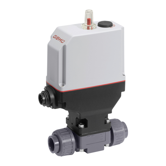
- Page 1 All manuals and user guides at all-guides.com GEMÜ R629 eSyLite Motorized diaphragm valve Operating instructions further information webcode: GW-R629...
- Page 2 All manuals and user guides at all-guides.com All rights including copyrights or industrial property rights are expressly reserved. Keep the document for future reference. © GEMÜ Gebr. Müller Apparatebau GmbH & Co. KG 08.05.2020 GEMÜ R629 2 / 37 www.gemu-group.com...
-
Page 3: Table Of Contents
14 Removal from piping ..........34 15 Disposal ..............34 16 Returns ..............34 17 Declaration of Incorporation according to 2006/42/ EC (Machinery Directive) ........... 35 18 Declaration of conformity according to 2014/30/EU (EMC Directive) ............36 3 / 37 www.gemu-group.com GEMÜ R629... -
Page 4: General Information
The following signal words and danger levels are used: DANGER Imminent danger! ▶ Non-observance can cause death or severe injury. WARNING Potentially dangerous situation! ▶ Non-observance can cause death or severe injury. GEMÜ R629 4 / 37 www.gemu-group.com... -
Page 5: Safety Information
8. Observe the safety regulations for the media used. 3.2 Description During operation: The GEMÜ R629 eSyLite 2/2-way diaphragm valve is motor- ized. It is available as an OPEN/CLOSE version. An integral 9. Keep this document available at the place of use. - Page 6 The product is designed for installation in piping systems and for controlling a working medium. The product is not intended for use in potentially explosive areas. ● Use the product in accordance with the technical data. GEMÜ R629 6 / 37 www.gemu-group.com...
-
Page 7: Order Data
2 DN DN 25 3 Body configuration 2/2-way body 4 Connection type Union end with DIN insert (socket) 5 Valve body material PVC-U, grey 6 Diaphragm material EPDM 7 Voltage/Frequency 24 V DC 7 / 37 www.gemu-group.com GEMÜ R629... - Page 8 All manuals and user guides at all-guides.com 5 Order data Order option Code Description 8 Control module Open/Close control (economy) 9 Actuator version Actuator size 1 diaphragm size 20 10 Mounting plate Standard 8 / 37 GEMÜ R629 www.gemu-group.com...
-
Page 9: Technical Data
The pressure rating (PN) depends on the connection code. Data for extended temperature ranges on request. Please note that the ambient temperature and media tem- perature generate a combined temperature at the valve body which must not exceed the above values. 9 / 37 www.gemu-group.com GEMÜ R629... -
Page 10: Diaphragm Material Code
DIN EN 61800-3 Interference resistance: DIN EN 61326-1 (industrial processes) DIN EN 61800-3 Food: FDA* USP* Class VI * depending on version and/or operating parameters 6.5 Materials Materials: Diaphragm material O-ring material PTFE EPDM EPDM EPDM 10 / 37 GEMÜ R629 www.gemu-group.com... -
Page 11: Duty Cycle And Service Life
Code 78: Union end with DIN insert (for IR butt welding) 6.7 Duty cycle and service life Service life: Class A acc. to EN 15714-2 Minimum 50,000 switching cycles at room temperature and permissible duty cycle. Duty cycle: max. 30% duty 11 / 37 www.gemu-group.com GEMÜ R629... - Page 12 6.8.2 Emergency power supply module Charging current: MG 10, MG 20, MG 25: max. 0.16 A MG 40: 0.32 A Charging time: approx. 13 min Service life: Guide value at 25 °C ambient temperature, approx. 3 years 12 / 37 GEMÜ R629 www.gemu-group.com...
-
Page 13: Dimensions
195.0 66.0 59.5 134.5 115.0 82.0 204.0 75.0 59.5 134.5 115.0 82.0 228.0 91.0 80.0 167.0 147.5 94.5 Dimensions in mm MG = diaphragm size * CT = A + H1 (see body dimensions) 13 / 37 www.gemu-group.com GEMÜ R629... -
Page 14: Body Dimensions
2) Valve body material Code 1: PVC-U, grey Code 4: ABS Code 5: PP, reinforced Code 20: PVDF Code 71: Inliner PP-H, grey, outliner PP, reinforced Code 75: Inliner PVDF/outliner PP, reinforced Code N5: PP-H, natural 14 / 37 GEMÜ R629 www.gemu-group.com... - Page 15 G 2 3/4 103.0 184.0 63.2 23.2 266.0 Dimensions in mm MG = diaphragm size 1) Connection type Code 7R: Union end with Rp threaded socket insert 2) Valve body material Code 1: PVC-U, grey 15 / 37 www.gemu-group.com GEMÜ R629...
- Page 16 1) Connection type Code 33: Union end with inch insert - BS (socket) Code 3M: Union end with inch insert – ASTM (socket) 2) Valve body material Code 1: PVC-U, grey Code 4: ABS 16 / 37 GEMÜ R629 www.gemu-group.com...
- Page 17 G 2 3/4 103.0 184.0 63.2 23.2 266.0 60.0 Dimensions in mm MG = diaphragm size 1) Connection type Code 3T: Union end with JIS insert (socket) 2) Valve body material Code 1: PVC-U, grey 17 / 37 www.gemu-group.com GEMÜ R629...
- Page 18 Code 78: Union end with DIN insert (for IR butt welding) 2) Valve body material Code 20: PVDF Code 5: PP, reinforced Code 71: Inliner PP-H, grey, outliner PP, reinforced Code 75: Inliner PVDF/outliner PP, reinforced Code N5: PP-H, natural 18 / 37 GEMÜ R629 www.gemu-group.com...
- Page 19 Code 30: Imperial butt weld spigot 2) Valve body material Code 1: PVC-U, grey Code 20: PVDF Code 4: ABS Code 5: PP, reinforced Code 71: Inliner PP-H, grey, outliner PP, reinforced Code 75: Inliner PVDF/outliner PP, reinforced 19 / 37 www.gemu-group.com GEMÜ R629...
- Page 20 Code 20: Spigot for IR butt welding Code 28: Spigot for IR butt welding, BCF 2) Valve body material Code 20: PVDF Code 71: Inliner PP-H, grey, outliner PP, reinforced Code 75: Inliner PVDF/outliner PP, reinforced 20 / 37 GEMÜ R629 www.gemu-group.com...
- Page 21 Code 4: Flange EN 1092, PN 10, form B, face-to-face dimension FTF EN 558 series 1, ISO 5752, basic series 1 2) Valve body material Code 1: PVC-U, grey Code 71: Inliner PP-H, grey, outliner PP, reinforced Code 75: Inliner PVDF/outliner PP, reinforced 21 / 37 www.gemu-group.com GEMÜ R629...
- Page 22 Code 39: Flange ANSI Class 125/150 RF, face-to-face dimension FTF EN 558 series 1, ISO 5752, basic series 1, length only for body con- figuration D 2) Valve body material Code 1: PVC-U, grey Code 71: Inliner PP-H, grey, outliner PP, reinforced Code 75: Inliner PVDF/outliner PP, reinforced 22 / 37 GEMÜ R629 www.gemu-group.com...
- Page 23 40.0 62.0 134.0 44.5 15.0 26.5 40.0 62.0 Dimensions in mm MG = diaphragm size 1) Connection type Code 75: Flare connection with PVDF union nut 2) Valve body material Code N5: PP-H, natural 23 / 37 www.gemu-group.com GEMÜ R629...
- Page 24 Material code 1 ø D 16.0 13.0 27.5 12.5 55.0 Dimensions in mm MG = diaphragm size 1) Connection type Code 2: Solvent cement socket DIN 2) Valve body material Code 1: PVC-U, grey 24 / 37 GEMÜ R629 www.gemu-group.com...
-
Page 25: Valve Body Mounting
35.0 MG 20 DN 15 - 25 25.0 MG 25 DN 32 25.0 MG 40 DN 40, DN 50 44.5 Dimensions in mm 7.4 Mounting plate ø5,5 Dimensions in mm, MG = diaphragm size 25 / 37 www.gemu-group.com GEMÜ R629... -
Page 26: Manufacturer's Information
Do not use the product as a step or a foothold. ● NOTICE Suitability of the product! ▶ The product must be appropriate for the piping system operating conditions (medium, medium concentration, temperature and pressure) and the prevailing ambient conditions. GEMÜ R629 26 / 37 www.gemu-group.com... -
Page 27: Installation Position
4. Weld the body of the product in the piping. 5. Allow butt weld spigots to cool down. 6. Mount actuator A (see chapter "Mounting the actuator"). 7. Re-attach or reactivate all safety and protective devices. 8. Flush the system. www.gemu-group.com 27 / 37 GEMÜ R629... -
Page 28: Installation With Union Ends
7. Connect the valve flange and the piping flange using ap- propriate sealing materials and matching bolting. 8. Use all flange holes. 9. Tighten the bolts diagonally. 10. Re-attach or reactivate all safety and protective devices. GEMÜ R629 28 / 37 www.gemu-group.com... -
Page 29: Electrical Connection
▶ The appropriate connector is included for X1. 10.1.1 Position of the connectors 10.1.2 Electrical connection Connection X1 7-pin plug, Binder, type 693 Signal name 24 V supply voltage Digital input OPEN Digital input CLOSED n. c. n. c. n. c. 29 / 37 www.gemu-group.com GEMÜ R629... -
Page 30: Operation
Cycle Counter. 2. Operate the manual override 3 with the hexagon socket (WAF3). ð Turn clockwise to close the valve. ð Turn anticlockwise to open the valve. GEMÜ R629 30 / 37 www.gemu-group.com... - Page 31 3. Clean all parts of contamination (do not damage parts during cleaning). NOTICE 4. Check parts for potential damage, replace if necessary (only use genuine parts from GEMÜ). ▶ The compressor is loose and can fall out. www.gemu-group.com 31 / 37 GEMÜ R629...
- Page 32 10. Press the diaphragm face tightly onto the backing dia- tightness. phragm manually so that it returns to its original shape 9. Carry out initialisation. and fits closely on the backing diaphragm. 11. Align the weir of compressor and diaphragm in parallel. GEMÜ R629 32 / 37 www.gemu-group.com...
- Page 33 Check the body of the GEMÜ product for corroded potential damage, replace body if necessary Incorrect installation Check installation of valve body in piping Valve body connection to piping leaks Incorrect installation Check installation of valve body in piping 33 / 37 www.gemu-group.com GEMÜ R629...
-
Page 34: Removal From Piping
2. Request a return delivery note from GEMÜ. 2. Dispose of all parts in accordance with the disposal regu- 3. Complete the return delivery note. lations/environmental protection laws. 4. Send the product with a completed return delivery note to GEMÜ. GEMÜ R629 34 / 37 www.gemu-group.com... -
Page 35: Declaration Of Incorporation According To 2006/42/Ec (Machinery Directive)
Important note! The partly completed machinery may be put into service only if it was determined, where appropriate, that the machinery into which the partly completed machinery is to be installed meets the provisions of this Directive. Ingelfingen-Criesbach 2020-04-08 Joachim Brien Head of Technical Department 35 / 37 www.gemu-group.com GEMÜ R629... -
Page 36: Declaration Of Conformity According To 2014/30/Eu (Emc Directive)
Description of the product: GEMÜ R629 Technical standards used: Interference resistance: – DIN EN 61326-1 (industrial processes) – DIN EN 61800-3 Interference emission: – DIN EN 61800-3 Ingelfingen-Criesbach 2020-01-28 Joachim Brien Head of Technical Department 36 / 37 GEMÜ R629 www.gemu-group.com... - Page 37 All manuals and user guides at all-guides.com GEMÜ Gebr. Müller Apparatebau GmbH & Co. KG Subject to alteration Fritz-Müller-Straße 6-8, 74653 Ingelfingen-Criesbach, *88658324* Germany 05.2020 | 88658324 Phone +49 (0)7940 123-0 · info@gemue.de www.gemu-group.com...
Need help?
Do you have a question about the R629 eSyLite and is the answer not in the manual?
Questions and answers