Table of Contents
Advertisement
Available languages
Available languages
Advertisement
Chapters
Table of Contents

Related Manuals for Gemu 650


Summary of Contents for Gemu 650
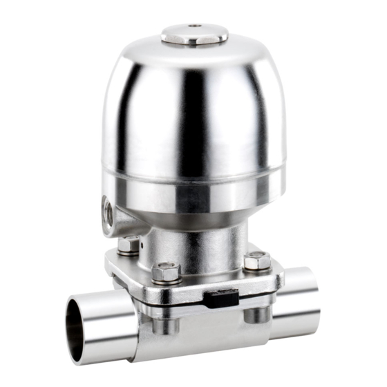
- Page 1 Membranventil Metall, DN 4 - 100 Diaphragm valve Metal, DN 4 - 100 ORIGINAL EINBAU- UND MONTAGEANLEITUNG INSTALLATION, OPERATING AND MAINTENANCE INSTRUCTIONS DN 100 "T" Antriebsausführung "T" Antriebsausführung "D" Actuator version "T" Actuator version "D"...
-
Page 2: Table Of Contents
Inhaltsverzeichnis Allgemeine Hinweise Voraussetzungen für die einwandfreie Allgemeine Hinweise Funktion des GEMÜ-Ventils: Allgemeine Sicherheitshinweise 2 Sachgerechter Transport und Lagerung Hinweise für Service- Installation und Inbetriebnahme durch und Bedienpersonal eingewiesenes Fachpersonal Warnhinweise Bedienung gemäß dieser Einbau- und Verwendete Symbole Montageanleitung Begriff sbestimmungen Ordnungsgemäße Instandhaltung Vorgesehener Einsatzbereich Technische Daten... -
Page 3: Hinweise Für Service
Hinweise für Service- Warnhinweise und Bedienpersonal Warnhinweise sind, soweit möglich, nach Die Einbau- und Montageanleitung enthält folgendem Schema gegliedert: grundlegende Sicherheitshinweise, die bei SIGNALWORT Inbetriebnahme, Betrieb und Wartung zu beachten sind. Nichtbeachtung kann zur Art und Quelle der Gefahr Folge haben: Mögliche Folgen bei Nichtbeachtung. -
Page 4: Begriffsbestimmungen
Mögliche Betätigungsfunktionen des explosionsgefährdeten Zonen Membranventils. verwendet werden, die auf der Vorgesehener Einsatzbereich Konformitätserklärung (ATEX) Das GEMÜ-Membranventil 650 ist für bestätigt wurden. den Einsatz in Rohrleitungen konzipiert. Es steuert ein durchfließendes Medium indem es durch ein Steuermedium geschlossen oder geöffnet werden kann. - Page 5 Steuermedium Neutrale Gase Max. zul. Temp. des Steuermediums 60 °C Füllvolumen Membran- Antriebs- Antriebs- Steuer- Steuer- Federsatz größe größe ausführung funktion 1 funktion 2 0,01 dm³ 0,01 dm³ 4 bis 15 0,02 dm³ 0,01 dm³ 10 bis 20 T/R/D/B 0,03 dm³ 0,07 dm³...
- Page 6 Steuerdruck [bar] Steuerfunktion Antriebsausführung Steuerdruck 0T1, 0R1 5,0 bis 7,0 0TA, 0RA 3,5 bis 7,0 4 bis 15 0T1, 0R1 max. 5,5 2 + 3 0TA, 0RA max. 4,5 1T1, 1R1, 1D1, 1B1 4,5 bis 7,0 10 bis 20 2 + 3 1T1, 1R1, 1D1, 1B1 max.
- Page 7 Autoklavierbarkeit Antriebsgröße 0 Standardausführung autoklavierbar Antriebsgröße 1 Standardausführung autoklavierbar Antriebsgröße 2 Standardausführung autoklavierbar Antriebsgröße 3 mit Sonderausführung Antriebsgröße 4 mit Sonderausführung Antriebsgröße 5 nicht möglich Antriebsgröße 6 nicht möglich Antriebsgröße 8 nicht möglich Steuerfunktion 2 + 3 Steuerfunktion 2 + 3 mit Elastomer-Membrane mit Elastomer-Membrane Membrangröße 8 bis 25...
-
Page 8: Bestelldaten (2/2-Wege-Ventile)
Bestelldaten (2/2-Wege-Ventile) Gehäuseform Code Ventilkörperwerkstoff Code Bodenablasskörper (Ausführung Antrieb T) 1.4435, Feinguss Zweiwege-Durchgangskörper 1.4408, Feinguss (Ausführung Antrieb D und T) 1.4408, PFA-Auskleidung T-Körper (Ausführung Antrieb T) 1.4435 (316L), Schmiedekörper * Abmessungen siehe Broschüre T-Ventile 1.4435 (316L), Vollmaterial ** Abmessungen und Ausführungen auf Anfrage 1.4435 (BN2), Schmiedekörper Δ... - Page 9 Innenoberfl ächengüten für Schmiede- und Vollmaterialkörper Mechanisch poliert Elektropoliert Medienberührte Hygieneklasse Hygieneklasse Innenoberflächen Code Code DIN 11866 DIN 11866 Ra ≤ 0,80 μm 1502 1503 Ra ≤ 0,60 μm 1507 1508 Ra ≤ 0,40 μm 1536 1537 Ra ≤ 0,25 μm 1527 1516 Mechanisch poliert...
-
Page 10: Herstellerangaben
Herstellerangaben Funktionsbeschreibung GEMÜ 650 ist ein Metall-Membranventil mit Zweiwege-Durchgangs-, T- oder Transport Bodenablasskörper bzw. Ausführung in Mehrwege-Ausführung. Das Ventil verfügt Membranventil nur auf geeignetem Lademittel transportieren, nicht stürzen, über einen Kolbenantrieb sowie serienmäßig über eine optische Stellungsanzeige. vorsichtig handhaben. Alle Antriebsteile inkl. Schließfedern... -
Page 11: Typenschild
Typenschild VORSICHT Geräteversion Ausführung gemäß Bestelldaten Ventil nicht als Trittstufe oder gerätespezifische Daten Aufstiegshilfe benutzen! Gefahr des Abrutschens / ® der Beschädigung des Ventils. Baujahr VORSICHT Maximal zulässigen Druck nicht 12103529 I 0001 überschreiten! Rückmeldenummer Eventuell auftretende Druckstöße Artikelnummer Seriennummer ®... -
Page 12: Steuerfunktionen
Antriebs bewirkt das Schließen des Ventils Clampanschlüsse: Drehwinkel durch Federkraft. für das entleerungsoptimierte Einschweißen entnehmen Sie Steuerfunktion 2 bitte der Broschüre "Drehwinkel für Federkraft geöffnet (NO): 2/2-Wege-Ventilkörper" (auf Anfrage Ruhezustand des Ventils: durch Federkraft oder unter www.gemu-group.com). geöffnet. Ansteuern des Antriebs 12 / 52... -
Page 13: Steuermedium Anschließen
(Anschluss 4) schließt das Ventil. Entlüften Gewinde der Steuermediumanschlüsse: des Antriebs bewirkt das Öffnen des Ventils Membrangröße 8: G1/8 durch Federkraft. Membrangröße 10 - 100: G1/4 Steuerfunktion Anschlüsse Steuerfunktion 3 Federkraft Beidseitig angesteuert (DA): 2: Steuermedium (Öffnen) geschlossen (NC) Ruhezustand des Ventils: durch Federkraft Federkraft geöffnet. -
Page 14: Montage / Demontage Von Ersatzteilen
11 Montage / Demontage 11.2 Demontage Membrane von Ersatzteilen Wichtig: Vor Demontage der Membrane bitte Antrieb demontieren, siehe "Demontage Ventil (Antrieb vom Körper lösen)". 1. Membrane herausschrauben bzw. herausziehen (Membrangröße 8). 2. Alle Teile von Produktresten und Verschmutzungen reinigen. Teile dabei nicht zerkratzen oder beschädigen! 3. - Page 15 Membrangröße 10: Wichtig: Druckstück und Antriebsflansch von unten Ist die Membrane nicht weit gesehen: genug in das Verbindungsstück eingeschraubt, wirkt die Schließkraft direkt auf den Membranpin und nicht über Bild 1 das Druckstück. Das führt zu Beschädigungen und frühzeitigem Ausfall der Membrane und Undichtheit des Ventils.
-
Page 16: Montage Der Konkav-Membrane
11.3.2 Montage der Membrangröße 25 - 80: Konkav-Membrane Druckstück und Antriebsflansch von unten gesehen: Membrangröße 8 Membrane zum Einknüpfen: Druckstückaussparung Lasche Befestigungs- zapfen 1. Antrieb A in Geschlossen-Position bringen. 2. Membrane 2 mit angeformtem Befestigungszapfen schräg an Druckstückaussparung ansetzen. Druckstück lose auf Antriebsspindel Wichtig: aufsetzen, Aussparungen D in Führungen C Keine Fette oder Schmierstoff... -
Page 17: Montage Der Konvex-Membrane
3. Kontrollieren ob das Druckstück in den Verbin- Druckstückaussparung Führungen liegt. dungs- stück 4. Neue Membrane von Hand fest in Druckstück einschrauben. Druck- 5. Kontrollieren ob Membrandom in stück Druckstückaussparung liegt. 6. Bei Schwergängigkeit Gewinde prüfen, beschädigte Teile austauschen (nur Stützmembrane Membranpin Originalteile von GEMÜ... -
Page 18: Inbetriebnahme
13 Inspektion und Wartung 7. Komplett montiertes Ventil auf Dichtheit prüfen. WARNUNG Wichtig: Unter Druck stehende Armaturen! Wartung und Service: Gefahr von schwersten Verletzungen Membranen setzen sich im Laufe ® oder Tod! der Zeit. Nach Demontage / Nur an druckloser Anlage arbeiten. Montage des Ventils Schrauben 18 und Muttern 20 körperseitig auf VORSICHT... -
Page 19: Reinigung Und Sterilisation
14 Reinigung und Sterilisation 17 Rücksendung Das Ventil kann ohne Ausbau gereinigt Membranventil reinigen. (CIP) und sterilisiert (SIP) werden. Rücksendeerklärung bei GEMÜ Hierbei sind die Bedingungen unter anfordern. Kapitel "Technische Daten" (Betriebs-, Rücksendung nur mit vollständig Reinigungs- und Sterilisationsmedien, ausgefüllter Rücksendeerklärung. Temperaturen) einzuhalten. -
Page 20: Fehlersuche / Störungsbehebung
19 Fehlersuche / Störungsbehebung Fehler Möglicher Grund Fehlerbehebung Steuermedium entweicht aus Entlüftungsbohrung* / Entlüftung* im Oberteil des Antriebs bei Steuerfunktion Antriebskolben defekt Antrieb austauschen NC bzw. Anschluss 2 (siehe Kapitel 10.2 "Steuerfunktionen") bei Steuerfunktion NO Steuermedium entweicht aus Antrieb austauschen und Steuermedium Spindelabdichtung undicht Leckagebohrung* auf Verschmutzungen untersuchen... -
Page 21: Schnittbilder Und Ersatzteile
Stf. NC / Membrangrößen 10 - 50 Entlüftung bei Stf. NC / Membran- größe 8 Anschluss 2 Leckagebohrung Pos. Benennung Bestellbezeichnung Membrangrößen 8 - 50 / Antriebsausführung: T Ventilkörper K600... Membrane 600...M Schraube Scheibe 650...S30... Mutter Antrieb 9650... 21 / 52... - Page 22 Entlüftungsbohrung bei Stf. NC / Membrangrößen 10 - 50 Anschluss 2 Leckagebohrung Pos. Benennung Bestellbezeichnung Membrangrößen 10 - 50 / Antriebsausführung: D Ventilkörper K600... Membrane 600...M Schraube 650...S30... Scheibe Antrieb 9650... 22 / 52...
- Page 23 Entlüftungsbohrung bei Stf. NC Anschluss 2 Leckagebohrung Pos. Benennung Bestellbezeichnung Membrangröße 80 Ventilkörper K600... Membrane 600...M Schraube Scheibe 650...S30... Mutter Antrieb 9650... 23 / 52...
- Page 24 Entlüftungsbohrung bei Stf. NC Anschluss 2 Leckagebohrung Pos. Benennung Bestellbezeichnung Membrangröße 100 Ventilkörper K600... Membrane 600...M Scheibe 650...S30... Mutter Antrieb 9650... 24 / 52...
-
Page 25: Einbauerklärung
29.12.2009 Projektnummer: MV-Pneum-2009-12 Handelsbezeichnung: Typ 650 Es wird erklärt, dass die folgenden grundlegenden Anforderungen der Maschinenrichtlinie 2006/42/EG erfüllt sind: 1.1.3., 1.1.5., 1.2.1., 1.3., 1.3.2., 1.3.3., 1.3.4., 1.3.7., 1.3.9., 1.5.3., 1.5.5., 1.5.6., 1.5.7., 1.5.8., 1.5.9., 1.6.5. Ferner wird erklärt, dass die speziellen technischen Unterlagen gemäß Anhang VII Teil B erstellt wurden. - Page 26 GEMÜ Gebr. Müller Apparatebau GmbH & Co. KG Fritz-Müller-Straße 6-8 D-74653 Ingelfi ngen erklären, dass unten aufgeführte Armaturen die Sicherheitsanforderungen der Druckgeräterichtlinie 2014/68/EU erfüllen. Benennung der Armaturen - Typenbezeichnung Membranventil GEMÜ 650 Benannte Stelle: TÜV Rheinland Industrie Service GmbH Nummer: 0035 Zertifikat-Nr.: 01 202 926/Q-02 0036...
- Page 27 Contents General information Prerequisites to ensure that the GEMÜ valve General information functions correctly: General safety information Correct transport and storage Information for service and Installation and commissioning by trained operating personnel personnel Warning notes Operation according to these installation, Symbols used operating and maintenance instructions Defi...
-
Page 28: Information For Service And Operating Personnel
Information for service and Warning notes operating personnel Wherever possible, warning notes are organised according to the following The installation, operating and maintenance instructions contain fundamental safety scheme: information that must be observed during SIGNAL WORD commissioning, operation and maintenance. Non-compliance with these instructions may Type and source of the danger cause:... -
Page 29: Definition Of Terms
Intended area of use in the declaration of conformity (ATEX). The GEMÜ 650 diaphragm valve is designed for installation in piping systems. It controls a flowing medium by being closed or opened by a control medium. - Page 30 Control medium Inert gases Max. permissible temperature of control medium 60 °C Filling volume Diaphragm Actuator Actuator Control Control Spring set size size version function 1 function 2 0.01 dm³ 0.01 dm³ 4 to 15 0.02 dm³ 0.01 dm³ 10 to 20 T/R/D/B 0.03 dm³...
- Page 31 Control pressure [bar] Control function Actuator version Control pressure 0T1, 0R1 5.0 to 7.0 0TA, 0RA 3.5 to 7.0 4 to 15 0T1, 0R1 max. 5.5 2 + 3 0TA, 0RA max. 4.5 1T1, 1R1, 1D1, 1B1 4.5 to 7.0 10 to 20 2 + 3 1T1, 1R1, 1D1, 1B1...
- Page 32 Autoclavability Actuator size 0 Standard version with autoclave capability Actuator size 1 Standard version with autoclave capability Actuator size 2 Standard version with autoclave capability Actuator size 3 with special version Actuator size 4 with special version Actuator size 5 not possible Actuator size 6 not possible...
-
Page 33: Order Data (2/2-Way Valves)
Order data (2/2-way valves) Body confi guration Code Valve body material Code Tank bottom valve body (actuator version T) 1.4435, investment casting 2/2-way body (actuator version D and T) 1.4408, investment casting T body (actuator version T) 1.4408, PFA lined 1.4435 (316L), forged body * For dimensions see T Valves brochure ** Dimensions and versions on request... - Page 34 Internal surface fi nishes for forged and block material bodies Mechanically polished Electropolished Readings for Process Hygienic class Hygienic class Contact Surfaces Code Code DIN 11866 DIN 11866 Ra ≤ 0.80 μm 1502 1503 Ra ≤ 0.60 μm 1507 1508 Ra ≤...
-
Page 35: Manufacturer's Information
Manufacturer's information Functional description GEMÜ 650 is a metal diaphragm valve Transport with 2/2-way, T or tank bottom valve Only transport the diaphragm valve by body or multi-port design. The valve has suitable means. Do not drop. Handle a piston actuator and an optical position carefully. -
Page 36: Product Label
Product label CAUTION Device version Design in accordance with order data Never use the valve as a step or an aid Device-specific data for climbing! This entails the risk of slipping-off or ® damaging the valve. Year of CAUTION manu- facture Do not exceed the maximum 12103529 I 0001... -
Page 37: Control Functions
2) opens the valve. When the actuator is optimised draining see brochure vented, the valve is closed by spring force. "Angle of rotation for 2/2-way valve bodies" (on request or www.gemu- Control function 2 group.com). Normally open (NO): Valve resting position: opened by spring force. -
Page 38: Connecting The Control Medium
Control function 3 Thread size of the control medium Double acting (DA): connectors: Valve resting position: opened by spring Diaphragm size 8: G1/8 force. The valve is opened and closed by Diaphragm size 10 - 100: G1/4 activating the respective control medium Control function Connectors connectors (connector 2: open / connector... -
Page 39: Fitting/Removing Spare Parts
11 Fitting/removing spare parts 11.2 Removing the diaphragm Important: Before removing the diaphragm, please remove the actuator, see "Valve disassembly (removing actuator from body)". 1. Unscrew the diaphragm or pull it out (diaphragm size 8). 2. Clean all parts of remains of product and contaminants. - Page 40 Diaphragm size 10: Important: Compressor and actuator flange seen from If the diaphragm is not screwed below: into the adapter far enough, the closing force is transmitted directly onto the diaphragm pin and not via the compressor. This will cause Picture 1 damage and early failure of the diaphragm and thus leakage of the...
-
Page 41: Mounting A Concave Diaphragm
11.3.2 Mounting a Diaphragm size 25 - 80: concave diaphragm Compressor and actuator flange seen from below: Diaphragm size 8 Push-fit diaphragm: Recess of compressor Fastening spigot 1. Move actuator A to the closed position. 2. Place the diaphragm 2 with the fastening spigot in an inclined position at the recess of the compressor. -
Page 42: Mounting A Convex Diaphragm
3. Check if the compressor fits closely in the Adapter Recess of compressor guides. 4. Screw new diaphragm tightly into the compressor manually. Com- 5. Check if the diaphragm boss fits closely in pressor the recess of the compressor. 6. If it is difficult to screw it in, check the thread, replace damaged parts (only use Backing Diaphragm... -
Page 43: Commissioning
13 Inspection and maintenance Important: Service and maintenance: WARNING Diaphragms set in the course of time. After valve disassembly / The equipment is subject to pressure! assembly check that the bolts 18 Risk of severe injury or death! ® and nuts 20 on the body are tight Only work on depressurized plant. -
Page 44: Cleaning And Sterilization
14 Cleaning and sterilization 17 Returns The valve can be cleaned (CIP) and Clean the diaphragm valve. sterilized (SIP) without removal. The Request a return delivery note from conditions in chapter "Technical data" GEMÜ. (operating, cleaning and sterilization Returns must be made with a completed media, temperatures) must be observed. -
Page 45: Troubleshooting / Fault Clearance
19 Troubleshooting / Fault clearance Error Possible cause Troubleshooting Control medium escapes from vent hole*/vent* in the actuator cover for control function NC Piston faulty Replace the actuator or connector 2 for control function NO (see chapter 10.2 "Control functions"). Control medium escapes from Replace the actuator and check control Spindle seal leaking... -
Page 46: Sectional Drawings And Spare Parts
10 - 50 Vent for c.f. NC / diaphragm size 8 Connector 2 Leak detection hole Item Name Order designation Diaphragm sizes 8 - 50 / Actuator version: T Valve body K600... Diaphragm 600...M Bolt Washer 650...S30... Actuator 9650... 46 / 52... - Page 47 NC / diaphragm sizes 10 - 50 Connector 2 Leak detection hole Item Name Order designation Diaphragm sizes 10 - 50 / Actuator version: D Valve body K600... Diaphragm 600...M Bolt 650...S30... Washer Actuator 9650... 47 / 52...
- Page 48 Vent hole for c.f. NC Connector 2 Leak detection hole Item Name Order designation Diaphragm size 80 Valve body K600... Diaphragm 600...M Bolt Washer 650...S30... Actuator 9650... 48 / 52...
- Page 49 Vent hole for c.f. NC Connector 2 Leak detection hole Item Name Order designation Diaphragm size 100 Valve body K600... Diaphragm 600...M Washer 650...S30... Actuator 9650... 49 / 52...
-
Page 50: Declaration Of Incorporation
29.12.2009 Project number: MV-Pneum-2009-12 Commercial name: Type 650 We hereby declare that the following essential requirements of the Machinery Directive 2006/42/EC have been fulfilled: 1.1.3., 1.1.5., 1.2.1., 1.3., 1.3.2., 1.3.3., 1.3.4., 1.3.7., 1.3.9., 1.5.3., 1.5.5., 1.5.6., 1.5.7., 1.5.8., 1.5.9., 1.6.5. -
Page 51: Eu Declaration Of Conformity
74653 Ingelfi ngen, Germany declare that the equipment listed below complies with the safety requirements of the Pressure Equipment Directive 2014/68/EU. Description of the equipment - product type Diaphragm valve GEMÜ 650 Notified body: TÜV Rheinland Industrie Service GmbH Number: 0035 Certificate no.:... - Page 52 GEMÜ Gebr. Müller Apparatebau GmbH & Co. KG · Fritz-Müller-Str. 6-8 · D-74653 Ingelfi ngen-Criesbach Telefon +49(0)7940/123-0 · Telefax +49(0)7940/123-192 · info@gemue.de · www.gemu-group.com...
Need help?
Do you have a question about the 650 and is the answer not in the manual?
Questions and answers