
Related Manuals for Gemu eSyDrive R649


Summary of Contents for Gemu eSyDrive R649
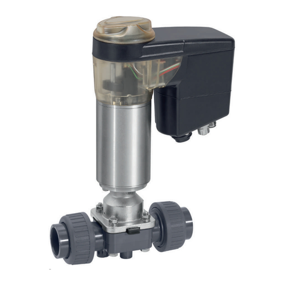
- Page 1 GEMÜ R649 eSyDrive Motorized diaphragm valve Operating instructions further information webcode: GW-R649...
- Page 2 All rights including copyrights or industrial property rights are expressly reserved. Keep the document for future reference. © GEMÜ Gebr. Müller Apparatebau GmbH & Co. KG 07.04.2021 GEMÜ R649 eSyDrive 2 / 50 www.gemu-group.com...
-
Page 3: Table Of Contents
20 Declaration of Incorporation according to 2006/42/ EC (Machinery Directive) ........... 47 21 Declaration of conformity according to 2014/68/EU (Pressure Equipment Directive) ......... 48 22 Declaration of conformity according to 2014/30/EU (EMC Directive) ............49 www.gemu-group.com 3 / 50 GEMÜ R649 eSyDrive... -
Page 4: General Information
The following signal words and danger levels are used: DANGER Imminent danger! ▶ Non-observance can cause death or severe injury. WARNING Potentially dangerous situation! ▶ Non-observance can cause death or severe injury. GEMÜ R649 eSyDrive 4 / 50 www.gemu-group.com... -
Page 5: Safety Information
14. Do not carry out any maintenance work and repairs not de- scribed in this document without consulting the manufac- turer first. In cases of uncertainty: 15. Consult the nearest GEMÜ sales office. www.gemu-group.com 5 / 50 GEMÜ R649 eSyDrive... - Page 6 Moves actuator to the closed position Manual opera- tion Starting initialisation Actuator switched off (OFF mode) Manual opera- tion (on-site) Software update alternating On-site initialisa- tion (buttons) Remote initial- isation (via Di- gIn) GEMÜ R649 eSyDrive 6 / 50 www.gemu-group.com...
-
Page 7: Product Label
DANGER CLOSED position Position indicator Danger of explosion LEDs, ▶ Risk of death or severe injury. inversed Do not use the product in potentially ● explosive zones. Position unknown (e.g. 50%) Initialisation alternating www.gemu-group.com 7 / 50 GEMÜ R649 eSyDrive... - Page 8 The product is designed for installation in piping systems and for controlling a working medium. The product is not intended for use in potentially explosive areas. ● Use the product in accordance with the technical data. GEMÜ R649 eSyDrive 8 / 50 www.gemu-group.com...
-
Page 9: Order Data
6 Diaphragm material Code PTFE/EPDM one-piece PTFE/EPDM two-piece 7 Voltage/Frequency Code 24 V DC 8 Control module Code ON/OFF, positioner and process controller 9 Actuator version Code 10 Mounting plate Code With mounting plate Without www.gemu-group.com 9 / 50 GEMÜ R649 eSyDrive... - Page 10 5 Valve body material PVC-U, grey 6 Diaphragm material 7 Voltage/Frequency 24 V DC 8 Control module ON/OFF, positioner and process controller 9 Actuator version 2 A Actuator size 2 10 Mounting plate Without GEMÜ R649 eSyDrive 10 / 50 www.gemu-group.com...
-
Page 11: Technical Data
PVDF (code 20) -10 — 80 °C Inliner PP-H grey / outliner PP, reinforced (code 5–80 °C Inliner PVDF / outliner PP, reinforced (code 75) -10 — 80 °C PP-H, natural (code N5) 5–80 °C www.gemu-group.com 11 / 50 GEMÜ R649 eSyDrive... - Page 12 0/4 - 20 mA; 0 – 10 V DC (selectable using software) Input type: passive Input resistance: 250 Ω Accuracy/linearity: ≤ ±0.3% of full flow Temperature drift: ≤ ±0.1% / 10°K Resolution: 12 bit GEMÜ R649 eSyDrive 12 / 50 www.gemu-group.com...
- Page 13 Load resistor: ≤ 750 kΩ Resolution: 10 bit Overload proof: Yes (up to ± 24 V DC) Short-circuit proof: 6.7.4 Digital output signals 6.7.4.1 Switching outputs 1 and 2 Design: 2x change-over contact, potential-free www.gemu-group.com 13 / 50 GEMÜ R649 eSyDrive...
- Page 14 The actuator and the PC must be in the same network to use the web server. The IP address of the actuator is entered in the web browser and the actuator can then be parametrised. In order to use more than one actuator, a definitive IP address must be assigned to each actuator in the same network. GEMÜ R649 eSyDrive 14 / 50 www.gemu-group.com...
- Page 15 6 Technical data 6.7.6 www.gemu-group.com 15 / 50 GEMÜ R649 eSyDrive...
-
Page 16: Dimensions
132.0 172.0 243.0 40, 50 360.0 124.0 134.0 157.0 224.0 296.0 360.0 124.0 134.0 157.0 224.0 296.0 Dimensions in mm, MG = diaphragm size * CT = A + H1 (see body dimensions) GEMÜ R649 eSyDrive 16 / 50 www.gemu-group.com... - Page 17 Code 30: Imperial butt weld spigot 2) Valve body material Code 1: PVC-U, grey Code 4: ABS Code 5: PP, reinforced Code 20: PVDF Code 71: Inliner PP-H, grey, outliner PP, reinforced Code 75: Inliner PVDF/outliner PP, reinforced www.gemu-group.com 17 / 50 GEMÜ R649 eSyDrive...
- Page 18 75.0 43.0 1) Connection type Code 20: Spigot for IR butt welding 2) Valve body material Code 20: PVDF Code 71: Inliner PP-H, grey, outliner PP, reinforced Code 75: Inliner PVDF/outliner PP, reinforced GEMÜ R649 eSyDrive 18 / 50 www.gemu-group.com...
- Page 19 ød 1/2'' 31,0 37,0 20,0 41,0 16,0 134,0 1) Connection type Code 28: Spigot for IR butt welding, BCF 2) Valve body material Code 20: PVDF Dimensions in mm MG = diaphragm size www.gemu-group.com 19 / 50 GEMÜ R649 eSyDrive...
- Page 20 32.0 60.0 39.0 13.0 116.0 166.0 170.0 158.0 162.0 G 1½ 1¼" 40.0 74.0 41.0 15.0 134.0 192.0 196.0 181.0 184.0 1½" 50.0 83.0 63.2 23.2 154.0 222.0 222.0 207.0 210.0 G 2¼ GEMÜ R649 eSyDrive 20 / 50 www.gemu-group.com...
- Page 21 2) Valve body material Code 1: PVC-U, grey Code 4: ABS Code 5: PP, reinforced Code 20: PVDF Code 71: Inliner PP-H, grey, outliner PP, reinforced Code 75: Inliner PVDF/outliner PP, reinforced Code N5: PP-H, natural www.gemu-group.com 21 / 50 GEMÜ R649 eSyDrive...
- Page 22 Code 4: ABS 7.2.6 Union end DIN (code 78 / MG 10) Connection type code 78 Material code 20, N5 20, N5 øD ød 90.0 196.0 42.0 20.0 36.0 30.0 41.0 15.0 16.0 GEMÜ R649 eSyDrive 22 / 50 www.gemu-group.com...
- Page 23 Code 78: Union end with insert (for IR butt welding) – DIN 2) Valve body material Code 5: PP, reinforced Code 20: PVDF Code 71: Inliner PP-H, grey, outliner PP, reinforced Code 75: Inliner PVDF/outliner PP, reinforced Code N5: PP-H, natural www.gemu-group.com 23 / 50 GEMÜ R649 eSyDrive...
- Page 24 G 2¼ 1½ 2" 103.0 63.2 23.2 184.0 266.0 G 2¾ 1) Connection type Code 7R: Union end with insert (Rp threaded socket) - DIN 2) Valve body material Code 1: PVC-U, grey GEMÜ R649 eSyDrive 24 / 50 www.gemu-group.com...
- Page 25 Connection type solvent cement socket (code 2) , body material PVC-U (code 1) ø D 1/2" 16.0 27.5 12.5 55.0 13.0 1) Connection type Code 2: Solvent cement socket DIN 2) Valve body material Code 1: PVC-U, grey www.gemu-group.com 25 / 50 GEMÜ R649 eSyDrive...
- Page 26 Material code 5, 20 71, 75 5, 20 71, 75 5, 20 71, 75 5, 20 71, 75 øD øL ød øk 130.0 36.0 10.0 95.0 95.0 14.0 14.0 45.0 45.0 65.0 65.0 GEMÜ R649 eSyDrive 26 / 50 www.gemu-group.com...
- Page 27 Code 4: Flange EN 1092, PN 10, form B, face-to-face dimension FTF EN 558 series 1, ISO 5752, basic series 1 2) Valve body material Code 1: PVC-U, grey Code 5: PP, reinforced Code 20: PVDF Code 71: Inliner PP-H, grey, outliner PP, reinforced Code 75: Inliner PVDF/outliner PP, reinforced www.gemu-group.com 27 / 50 GEMÜ R649 eSyDrive...
- Page 28 16.0 1" 63.0 115.0 160.0 39.0 13.0 79.0 16.0 1¼" 73.0 140.0 180.0 41.0 15.0 89.0 16.0 1½" 82.0 150.0 200.0 63.2 23.2 98.0 16.0 2" 102.0 165.0 230.0 63.2 23.2 121.0 19.0 GEMÜ R649 eSyDrive 28 / 50 www.gemu-group.com...
- Page 29 Code 39: Flange ANSI Class 125/150 RF, face-to-face dimension FTF EN 558 series 1, ISO 5752, basic series 1, length only for body config- uration D 2) Valve body material Code 1: PVC-U, grey Code 5: PP, reinforced Code 20: PVDF Code 71: Inliner PP-H, grey, outliner PP, reinforced Code 75: Inliner PVDF/outliner PP, reinforced 7.2.12 www.gemu-group.com 29 / 50 GEMÜ R649 eSyDrive...
-
Page 30: Availability Of Mounting Plate
7 Dimensions 7.3 Valve body mounting See also 2 Valve body mounting [} 30] 7.4 Availability of mounting plate ø5,5 Dimensions in mm, MG = diaphragm size GEMÜ R649 eSyDrive 30 / 50 www.gemu-group.com... - Page 31 31 / 50 GEMÜ R649 eSyDrive...
- Page 32 8.2 Connection X2 5-pin M12 built-in socket, D-coded Signal name Pin 1 Tx + (Ethernet) Pin 2 Rx + (Ethernet) Pin 3 Tx - (Ethernet) Pin 4 Rx - (Ethernet) Pin 5 Shield GEMÜ R649 eSyDrive 32 / 50 www.gemu-group.com...
-
Page 33: Manufacturer's Information
▶ Risk of severe injury or death. Depressurize the plant. ● 9.2 Packaging Completely drain the plant. ● The product is packaged in a cardboard box which can be re- cycled as paper. www.gemu-group.com 33 / 50 GEMÜ R649 eSyDrive... -
Page 34: Installation Position
(medium, medium concentration, temperature and pressure) and the prevailing ambient 10.2 Installation position conditions. The installation position of the product is optional. 10.3 Installation with clamp connections Fig. 4: Clamp connection GEMÜ R649 eSyDrive 34 / 50 www.gemu-group.com... -
Page 35: Installation With Butt Weld Spigots
3. Screw the threaded connections into the pipe in accord- ance with valid standards. 4. Screw the body of the product onto the piping using ap- propriate thread sealant. 5. Re-attach or reactivate all safety and protective devices. www.gemu-group.com 35 / 50 GEMÜ R649 eSyDrive... - Page 36 7. Connect the valve flange and the piping flange using ap- propriate sealing materials and matching bolting. 8. Use all flange holes. 9. Tighten the bolts diagonally. 10. Re-attach or reactivate all safety and protective devices. GEMÜ R649 eSyDrive 36 / 50 www.gemu-group.com...
-
Page 37: Electrical Connection
Relay output K2, common Pin 6 Relay output K2, make contact Pin PE Function earth 11.2 Connection X2 5-pin M12 built-in socket, D-coded Signal name Pin 1 Tx + (Ethernet) Pin 2 Rx + (Ethernet) www.gemu-group.com 37 / 50 GEMÜ R649 eSyDrive... - Page 38 5. Correctly close the actuator cover/manual override again immediately after use (see chapter "Manual override" (see “Manual override“, page 40)). 6. Correctly close the product again after replacing the dia- phragm (see chapter "Diaphragm replacement"). GEMÜ R649 eSyDrive 38 / 50 www.gemu-group.com...
- Page 39 11 Electrical connection 11.6 www.gemu-group.com 39 / 50 GEMÜ R649 eSyDrive...
-
Page 40: Network Connection
4. Place the actuator of housing cover 12 in the starting 14.1 Operation on the device point for manual override. 14.1.1 Moving the valve to the open position 1. Move the "ON-Site" DIP switch 8 to the "ON" position. GEMÜ R649 eSyDrive 40 / 50 www.gemu-group.com... -
Page 41: Inspection And Maintenance
8. Ensure correct positioning of the O-ring. 9. Push actuator 12 into the groove provided for this pur- pose. 10. Turn housing cover 3 anticlockwise until it stops. ð The actuator cover is closed. 11. Reconnect the power supply. www.gemu-group.com 41 / 50 GEMÜ R649 eSyDrive... - Page 42 ▶ Incorrectly mounted diaphragms cause the product leak- (only use genuine parts from GEMÜ). age and emission of medium. In this case, remove the diaphragms, check the complete valve and diaphragms and reassemble again proceeding as described above. GEMÜ R649 eSyDrive 42 / 50 www.gemu-group.com...
- Page 43 1. Move the actuator A to the open position. 2. Position actuator A with the mounted diaphragm on the valve body. 3. Screw in bolts, washers and nuts hand tight. www.gemu-group.com 43 / 50 GEMÜ R649 eSyDrive...
- Page 44 7. Ensure even compression of the diaphragm (approx. 10 to 15%). ð Even compression is detected by an even outer bulge. 8. With the valve fully assembled, check the function and tightness. 9. Carry out initialisation. GEMÜ R649 eSyDrive 44 / 50 www.gemu-group.com...
-
Page 45: Troubleshooting
LED 1 flashes yellow Actual value signal outside of the area Check actual value signal LED 1 and 2 are flashing yellow and red No calibration Contact GEMÜ simultaneously Internal error Contact GEMÜ www.gemu-group.com 45 / 50 GEMÜ R649 eSyDrive... -
Page 46: Removal From Piping
2. Request a return delivery note from GEMÜ. 2. Dispose of all parts in accordance with the disposal regu- 3. Complete the return delivery note. lations/environmental protection laws. 4. Send the product with a completed return delivery note to GEMÜ. GEMÜ R649 eSyDrive 46 / 50 www.gemu-group.com... -
Page 47: Declaration Of Incorporation According To 2006/42/Ec (Machinery Directive)
Important note! The partly completed machinery may be put into service only if it was determined, where appropriate, that the machinery into which the partly completed machinery is to be installed meets the provisions of this Directive. 2020-05-20 Joachim Brien Head of Technical Department www.gemu-group.com 47 / 50 GEMÜ R649 eSyDrive... -
Page 48: Declaration Of Conformity According To 2014/68/Eu (Pressure Equipment Directive)
GEMÜ Gebr. Müller Apparatebau GmbH & Co. KG Fritz-Müller-Straße 6-8 74653 Ingelfingen-Criesbach, Germany declare that the product listed below complies with the safety requirements of the Pressure Equipment Directive 2014/68/EU. Description of the pressure equipment: GEMU R649 Notified body: TÜV Rheinland Industrie Service GmbH Number: 0035 Certificate no.:... -
Page 49: Declaration Of Conformity According To 2014/30/Eu (Emc Directive)
Description of the product: GEMÜ R649 Technical standards used: • DIN EN 61326-1 (industrial processes) Interference resistance: • DIN EN 61800-3 Interference emission: • DIN EN 61800-3 2020-05-20 Joachim Brien Head of Technical Department www.gemu-group.com 49 / 50 GEMÜ R649 eSyDrive... - Page 50 Subject to alteration GEMÜ Gebr. Müller Apparatebau GmbH & Co. KG *88659161* Fritz-Müller-Straße 6–8, 74653 Ingelfingen-Criesbach, Germany 04.2021 | 88659161 Phone +49 (0) 7940 1230 · info@gemue.de www.gemu-group.com...
Need help?
Do you have a question about the eSyDrive R649 and is the answer not in the manual?
Questions and answers