Table of Contents
Advertisement
Available languages
Available languages
Quick Links
Advertisement
Chapters
Table of Contents

Subscribe to Our Youtube Channel
Related Manuals for Gemu 9650100Z 26T1-C


Summary of Contents for Gemu 9650100Z 26T1-C
- Page 1 Membranventil Metall, DN 4 - 50 Diaphragm Valve Metal, DN 4 - 50 ORIGINAL EINBAU- UND MONTAGEANLEITUNG INSTALLATION, OPERATING AND MAINTENANCE INSTRUCTIONS DN 100 "T" Antriebsausführung "T" Antriebsausführung "D" Actuator version "T" Actuator version "D" 650_us...
-
Page 2: Table Of Contents
Inhaltsverzeichnis Allgemeine Hinweise Allgemeine Hinweise Voraussetzungen für die einwandfreie Funk- Allgemeine tion des GEMÜ-Ventils: Sicherheitshinweise Sachgerechter Transport und Lagerung. Hinweise für Service- Installation und Inbetriebnahme durch und Bedienpersonal eingewiesenes Fachpersonal. Warnhinweise Bedienung gemäß dieser Einbau- und Verwendete Symbole Montageanleitung. Begriff sbestimmungen Ordnungsgemäße Instandhaltung. -
Page 3: Hinweise Für Service- Und Bedienpersonal
Hinweise für Service- Warnhinweise und Bedienpersonal Warnhinweise sind, soweit möglich, nach folgendem Schema gegliedert: Die Einbau- und Montageanleitung enthält grundlegende Sicherheitshinweise, die bei SIGNALWORT Inbetriebnahme, Betrieb und Wartung zu be- achten sind. Nichtbeachtung kann zur Folge Art und Quelle der Gefahr haben: Mögliche Folgen bei Nichtbeachtung. -
Page 4: Begriff Sbestimmungen
Das Ventil darf nur gemäß den tech- Punkt: Beschreibt auszuführende nischen Daten eingesetzt werden Tätigkeiten. (siehe Kapitel 5 "Technische Daten"). Schrauben und Kunststoff teile am Pfeil: Beschreibt Reaktion(en) auf ® Membranventil nicht lackieren! Tätigkeiten. WARNUNG Aufzählungszeichen Membranventil nur bestimmungsgemäß einsetzen! Begriff... - Page 5 Steuermedium Neutrale Gase Max. zul. Temp. des Steuermediums 60 °C Füllvolumen Membran- Antriebs- Antriebs- Steuer- Steuer- Federsatz größe größe ausführung funktion 1 funktion 2 0,01 dm³ 0,01 dm³ 4 bis 15 0,02 dm³ 0,01 dm³ 10 bis 20 T/R/D/B 0,03 dm³ 0,07 dm³...
- Page 6 Steuerdruck [bar] Steuerfunktion Antriebsausführung Steuerdruck 0T1, 0R1 5,0 bis 7,0 0TA, 0RA 3,5 bis 7,0 4 bis 15 0T1, 0R1 max. 5,5 2 + 3 0TA, 0RA max. 4,5 1T1, 1R1, 1D1, 1B1 4,5 bis 7,0 10 bis 20 2 + 3 1T1, 1R1, 1D1, 1B1 max.
- Page 7 Autoklavierbarkeit Antriebsgröße 0 Standardausführung autoklavierbar Antriebsgröße 1 Standardausführung autoklavierbar Antriebsgröße 2 Standardausführung autoklavierbar Antriebsgröße 3 mit Sonderausführung Antriebsgröße 4 mit Sonderausführung Antriebsgröße 5 nicht möglich Antriebsgröße 6 nicht möglich Antriebsgröße 8 nicht möglich Steuerfunktion 2 + 3 Steuerfunktion 2 + 3 mit Elastomer-Membrane mit Elastomer-Membrane Membrangröße 8 bis 25...
-
Page 8: Bestelldaten (2/2-Wege-Ventile)
Bestelldaten (2/2-Wege-Ventile) Gehäuseform Code Ventilkörperwerkstoff Code Bodenablasskörper (Ausführung Antrieb T) 1.4435, Feinguss Zweiwege-Durchgangskörper 1.4408, Feinguss (Ausführung Antrieb D und T) 1.4408, PFA-Auskleidung T-Körper (Ausführung Antrieb T) 1.4435 (316L), Schmiedekörper * Abmessungen siehe Broschüre T-Ventile 1.4435 (316L), Vollmaterial ** Abmessungen und Ausführungen auf Anfrage 1.4435 (BN2), Schmiedekörper Δ... - Page 9 Innenoberfl ächengüten für Schmiede- und Vollmaterialkörper Mechanisch poliert Elektropoliert Medienberührte Hygieneklasse Hygieneklasse Innenoberflächen Code Code DIN 11866 DIN 11866 Ra ≤ 0,80 μm 1502 1503 Ra ≤ 0,60 μm 1507 1508 Ra ≤ 0,40 μm 1536 1537 Ra ≤ 0,25 μm 1527 1516 Mechanisch poliert...
-
Page 10: Herstellerangaben
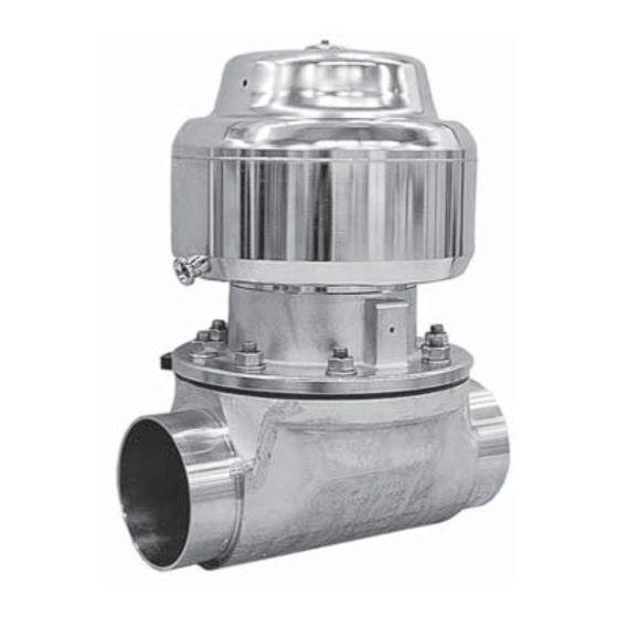
Herstellerangaben Funktionsbeschreibung GEMÜ 650 ist ein Metall-Membranventil mit Durchgangs-, T- oder Behälterboden- Transport Ablasskörper bzw. Ausführung in Mehr- Membranventil nur auf geeignetem wegeausführung. Das Ventil verfügt über Lademittel transportieren, nicht stürzen, einen Kolbenantrieb sowie serienmäßig vorsichtig handhaben. über eine optische Stellungsanzeige. Alle Verpackungsmaterial entsprechend Antriebsteile inkl. -
Page 11: Montage Und Bedienung
10 Montage und Bedienung Installationsort: Vor Einbau: VORSICHT Ventilkörper- und Membranwerkstoff Ventil äußerlich nicht stark beanspruchen. entsprechend Betriebsmedium auslegen. Installationsort so wählen, dass Ventil Eignung vor Einbau prüfen! nicht als Steighilfe genutzt werden kann. Siehe Kapitel 5 "Technische Daten". Rohrleitung so legen, dass Schub- und Biegungskräfte, sowie Vibrationen und 10.1 Montage des Spannungen vom Ventilkörper fernge-... -
Page 12: Steuerfunktionen
Montage bei Clampanschluss: Steuerfunktion 3 Bei Montage der Clampanschlüsse Beidseitig angesteuert (DA): entsprechende Dichtung zwischen Ruhezustand des Ventils: durch Federkraft Ventilkörper und Rohranschluss einlegen geöff net. Öff nen und Schließen des Ventils und mit Klammer verbinden. Die Dichtung durch ansteuern der entsprechenden Steu- sowie die Klammer der Clampanschlüsse ermediumanschlüsse (Anschluss 2: Öff... -
Page 13: Optische Stellungsanzeige
11.1 Demontage Ventil Steuerfunktion Anschluss (Antrieb vom Körper lösen) Federkraft ge- 2: Steuermedium (Öff nen) schlossen (NC) 1. Antrieb A in Off en-Position bringen. 2. Antrieb A vom Ventilkörper 1 Federkraft 4: Steuermedium (Schließen) demontieren. geöff net (NO) 3. Antrieb A in Geschlossen-Position Beidseitig 2: Steuermedium (Öff... -
Page 14: Montage Membrane
11.3 Montage Membrane Membrangröße 8: Das Druckstück ist fest montiert. Druckstück und Antriebsfl ansch von unten 11.3.1 Allgemeines gesehen: Wichtig: Für Ventil passende Membrane einbauen (geeignet für Medium, Mediumkonzentration, Tempera- tur und Druck). Die Absperrmem- brane ist ein Verschleißteil. Vor In- betriebnahme und über gesamte Membrangröße 10: Einsatzdauer des Membranventils... - Page 15 Membrangröße 25: Ist die Antriebsspindel nicht in der richtigen Das Druckstück ist lose. Position, muss sie in die richtige Position Druckstück und Antriebsfl ansch von unten gedreht werden. Die Position der Verdreh- gesehen: sicherung (A) ist gegenüber der Position der Druckstückführung (C) um 45°...
- Page 16 Membrangrößen 10 - 50 Membrane zum Einschrauben: Druckstückaussparung Membranschild Schraubpin Schraubpin 5. Neue Stützmembrane auf Druckstück aufl egen. 6. Membranschild auf Stützmembrane Membrandom aufl egen. 1. Antrieb A in Geschlossen-Position 7. Membranschild von Hand fest bringen. in Druckstück einschrauben. 2. Druckstück lose auf Antriebsspindel Der Membrandom muss in der aufsetzen, Aussparungen in Druckstückaussparung liegen.
-
Page 17: Montage Antrieb Auf Ventilkörper
11.4 Montage Antrieb VORSICHT auf Ventilkörper Gegen Leckage vorbeugen! 1. Antrieb A in Off en-Position bringen. Schutzmaßnahmen gegen Überschrei- 2. Antrieb A mit montierter Membrane 2 tung des maximal zulässigen Drucks auf Ventilkörper 1 aufsetzen, auf durch eventuelle Druckstöße (Wasser- Übereinstimmung von Druckstücksteg schläge) vorsehen. -
Page 18: Demontage
16 Rücksendung VORSICHT Membranventil reinigen. Wartungs- und Instandhaltungstätigkei- Rücksendung nur mit vollständig aus- ten nur durch geschultes Fachpersonal. gefüllter Rücksendeerklärung (anbei). Für Schäden welche durch unsachgemäße Handhabung oder Ansonsten erfolgt keine Fremdeinwirkung entstehen, Gutschrift bzw. keine übernimmt GEMÜ keinerlei Haftung. Erledigung der Reparatur Nehmen Sie im Zweifelsfall vor sondern eine kostenpfl... -
Page 19: Fehlersuche / Störungsbehebung
18 Fehlersuche / Störungsbehebung Fehler Möglicher Grund Fehlerbehebung Steuermedium entweicht aus Entlüftungsbohrung* / Entlüf- tung* im Oberteil des Antriebs bei Steuerfunktion 1 (NC) bzw. Steuerkolben defekt Antrieb austauschen Anschluss 2 (siehe Kapitel 10.2 " Steuerfunktionen") bei Steuerfunktion 2 (NO) Steuermedium entweicht aus Antrieb austauschen und Steuermedium Spindelabdichtung undicht Leckagebohrung*... -
Page 20: Schnittbild Und Ersatzteile
19 Schnittbild und Ersatzteile Entlüftungsbohrung bei Stf. 1 (NC) / Membrangröße 8 Entlüftung bei Stf. 1 (NC) / Membran- größen 10 - 50 Anschluss 2 Leckagebohrung Pos. Benennung Bestellbezeichnung Antriebsausführung: T Ventilkörper K600... Membrane 600...M Schraube Scheibe 650...S30... Mutter Antrieb 9650... -
Page 21: Einbauerklärung
20 Einbauerklärung Einbauerklärung im Sinne der EG-Maschinenrichtlinie 2006/42/EG, Anh. II, 1.B für unvollständige Maschinen Hersteller: GEMÜ Gebr. Müller Apparatebau GmbH & Co. KG Postfach 30 Fritz-Müller-Straße 6-8 D-74653 Ingelfingen-Criesbach Beschreibung und Indentifizierung der unvollständigen Maschine: Fabrikat: GEMÜ Membranventil pneumatisch betätigt Seriennummer: ab 29.12.2009 Projektnummer:... -
Page 22: Eg-Konformitätserklärung
21 EG-Konformitätserklärung Konformitätserklärung Gemäß der Richtlinie 97/23/EG Wir, die Firma GEMÜ Gebr. Müller GmbH & Co. KG Fritz-Müller-Straße 6-8 D-74653 Ingelfi ngen erklären, dass unten aufgeführte Armaturen die Sicherheitsanforderungen der Druckgeräte- richtlinie 97/23/EG erfüllen. Benennung der Armaturen - Typenbezeichnung Membranventil GEMÜ... -
Page 23: Notizen
Notizen 650_us 23 / 48... - Page 24 Contents General notes General notes Prerequisites for the correct function of the General safety notes GEMÜ valve: Notes for servicing and operating Correct transport and storage. personnel Installation and commissioning by trained Warning notes personnel. Symbols used Operation according to these installation, Defi...
-
Page 25: Notes For Servicing And Operating Personnel
Notes for servicing and Warning notes operating personnel Wherever possible, warning notes are organised according to the following scheme: The installation, operating and maintenance instructions contain fundamental safety notes that must be observed during commissioning, SIGNAL WORD operation and servicing. Type and source of the danger Non-observance can cause: Possible consequences of... -
Page 26: Defi Nition Of Terms
More detailed directions sign To avoid malfunction which could cause injury or damage, do not paint the bolts and plastic parts of the diaphragm Defi nition of terms valve! Working medium The medium that fl ows through the diaphragm WARNING valve. - Page 27 Control medium Inert gases Max. permissible temperature of control medium 140 °F Filling volume Diaphragm Actuator Actuator Control Control Spring set size size version function 1 function 2 0.61 cu in 0.61 cu in 4 to 15 1.22 cu in 0.61 cu in 10 to 20 T/R/D/B...
- Page 28 Autoclavability Actuator size 0 Standard version with autoclave capability Actuator size 1 Standard version with autoclave capability Actuator size 2 Standard version with autoclave capability Actuator size 3 with special version Actuator size 4 with special version Actuator size 5 not possible Actuator size 6 not possible...
- Page 29 Control pressure [psi] Control function Actuator version Control pressure 0T1, 0R1 75 to 105 0TA, 0RA 51 to 105 4 to 15 0T1, 0R1 max. 80 2 + 3 0TA, 0RA max. 65 1T1, 1R1, 1D1, 1B1 65 to 105 10 to 20 2 + 3 1T1, 1R1, 1D1, 1B1...
-
Page 30: Order Data (2/2-Way Valves)
Order data (2/2-way valves) Nominal size Code Connection Code DN 4 Butt weld spigots DN 6 NPS 1/8“ Spigots DIN DN 8 NPS 1/4“ Spigots EN 10357 series B (formerly DIN 11850 series 1) DN 10 NPS 3/8“ Spigot EN 10357 series A DN 12 G 3/8“... - Page 31 Control function Code Spring set Code Normally closed (NC) Standard Normally open (NO) For higher operating pressure Double acting (DA) (with opening spring) For higher operating pressure Internal surface fi nishes for forged and block material bodies Mechanically polished Electropolished Readings for Process Hygienic class Hygienic class...
-
Page 32: Manufacturer's Information
Manufacturer’s information Functional description GEMÜ 650 is a metal diaphragm valve with a 2/2-way, T or tank bottom valve body or Transport in multi-port design. The valve has a piston actuator and an optical position indicator as Only transport the diaphragm valve standard. -
Page 33: Installation And Operation
10 Installation and operation Installation work may only be performed by trained personnel. Prior to installation: Ensure that valve body and diaphragm Use appropriate protective gear as material are appropriate and compatible specifi ed in plant operator's guidelines. to handle the working medium. Check the suitability prior to the Installation location: installation. -
Page 34: Control Functions
10.2 Control functions Installation - Butt weld spigots: The following control functions are available: 1. Adhere to good welding practices! 2. Remove the actuator with the diaphragm Control function 1 before welding the valve body into the Normally closed (NC): pipeline (see chapter 12.1). -
Page 35: Connecting The Control Medium
10.4 Optical position indicator Connectors Control function 1 (NC) 2 (NO) 3 (DA) + = available / - = not available Valve open Valve closed (for connectors 2 / 4 see pictures on page 30) 10.3 Connecting the 11 Assembly / disassembly control medium of spare parts Important:... -
Page 36: Removing The Diaphragm
11.2 Removing the diaphragm Important: Incorrectly mounted diaphragm Important: may cause valve leakage / emission Before removing the diaphragm, of medium. In this case remove the please remove the actuator, see diaphragm, check the complete "Valve disassembly (removing valve and diaphragm and re- actuator from body)". - Page 37 Place the compressor loosely on the twisting. Ensure that the position of the anti- actuator spindle, fi t the grooves into the twist system is off set by 45° to the position of guides (arrows). The compressor must be the compressor guide (C). able to be moved freely between the guides! When mounting the compressor the pin must be properly engaged in the recess of the...
- Page 38 4. Align diaphragm tab (identifying manufacturer and material) in parallel to compressor weir. Diaphragm sizes 10 - 50 Diaphragm face Threaded pin type diaphragm: Threaded Recess of compressor Threaded 5. Position the new backing diaphragm onto the compressor. 6. Position the diaphragm face onto the backing diaphragm.
-
Page 39: Actuator Mounting On Valve Body
11.4 Actuator mounting on valve body WARNING Corrosive chemicals! 1. Move actuator A to the open position. Risk of caustic burns! 2. Position actuator A with the mounted ® Check the tightness of the diaphragm 2 on the valve body 1, take media connections prior to care to align the compressor weir and commissioning! -
Page 40: Disassembly
15 Disposal WARNING All valve parts must be Hot plant components! disposed of according to Risk of burns! ® relevant local or national Only work on plant that has disposal regulations / environ- cooled down. mental protection laws. Pay attention to adhered residual material and gas dif- WARNING fusion from penetrated media. -
Page 41: Troubleshooting / Fault Clearance
Troubleshooting / Fault clearance Fault Possible cause Fault clearance Control medium escapes from vent hole* / vent* in the actuator cover (control function 1 (NC)) or from Control piston faulty Replace actuator connector 2 (control function 2 (NO) (see chapter 10.2 "Control functions") Control medium escapes from Replace actuator and check control... -
Page 42: Sectional Drawing And Spare Parts
19 Sectional drawing and spare parts Vent hole for c.f. 1 (NC) / diaphragm size 8 Vent for c.f. 1 (NC) / diaphragm sizes 10 - 50 Connector 2 Leak detection hole Item Name Order description Actuator version: T Valve body K600... -
Page 43: Declaration Of Incorporation
20 Declaration of incorporation Declaration of Incorporation according to the EC Machinery Directive 2006/42/EC, Annex II, 1.B for partly completed machinery Manufacturer: GEMÜ Gebr. Müller Apparatebau GmbH & Co. KG Postfach 30 Fritz-Müller-Straße 6-8 D-74653 Ingelfingen-Criesbach Description and identification of the partly completed machinery: Make: GEMÜ... -
Page 44: Ec Declaration Of Conformity
21 EC Declaration of conformity Declaration of Conformity According of the Directive 97/23/EC Hereby we, GEMÜ Gebr. Müller GmbH & Co. KG Fritz-Müller-Straße 6-8 D-74653 Ingelfi ngen declare that the equipment listed below complies with the safety requirements of the Pressure Equipment Directive 97/23/EC. -
Page 45: Notes
Notes 650_us 45 / 48... - Page 46 Rücksendeerklärung (Kopiervorlage) Gesetzliche Bestimmungen, der Schutz der Umwelt und des Personals erfordern es, diese Erklärung vollständig ausgefüllt und unterschrieben den Versandpapieren beizulegen. Wenn diese Erklärung nicht vollständig ausgefüllt ist oder den Versandpapieren nicht beigelegt ist wird Ihre Rücksendung nicht bearbeitet! Wurde das Ventil / Gerät mit giftigen, ätzenden, brennbaren, aggressiven oder wassergefährdenden Medien betrieben, alle mediumsberührten Teile sorgfältig entleeren, dekontaminieren und spülen.
- Page 47 Goods return declaration (copy specimen) Legal regulations for the protection of the environment and personnel require that you include the completed and signed goods return declaration with your dispatch documents. If this declaration is not completed or not included with the dispatch documents, your return will not be processed! If the valve / device was operated with poisonous, corrosive, flammable, aggressive or water- endangering media, all medium wetted parts must be emptied carefully, decontaminated and rinsed.
- Page 48 VENTIL-, MESS- UND REGELSYSTEME VALVES, MEASUREMENT AND CONTROL SYSTEMS GEMÜ Gebr. Müller Apparatebau GmbH & Co. KG · Fritz-Müller-Str. 6-8 · D-74653 Ingelfi ngen-Criesbach Telefon +49(0)7940/123-0 · Telefax +49(0)7940/123-192 · info@gemue.de · www.gemue.de...
Need help?
Do you have a question about the 9650100Z 26T1-C and is the answer not in the manual?
Questions and answers
Hello, I would like to make sure that the Gemu 9650 actuator can be sterilised in an autoclave at 125°C for 30 minutes. Are there any special precautions to be taken? Thanks