
Related Manuals for Gemu 611


Summary of Contents for Gemu 611
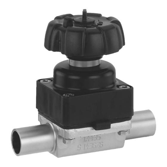
- Page 1 GEMÜ 611/671 Manually operated diaphragm valve Operating instructions further information webcode: GW-611/671...
- Page 2 All rights including copyrights or industrial property rights are expressly reserved. Keep the document for future reference. © GEMÜ Gebr. Müller Apparatebau GmbH & Co. KG 21.02.2023 GEMÜ 611/671 2 / 41 www.gemu-group.com...
-
Page 3: Table Of Contents
15 Removal from piping ..........16 Disposal .............. 17 Returns ..............18 EU Declaration of Conformity in accordance with 2014/68/EU (Pressure Equipment Directive) ..19 Manufacturer's declaration according to the Pres- sure Equipment Directive 2014/68/EU ....www.gemu-group.com 3 / 41 GEMÜ 611/671... -
Page 4: General Information
The following signal words and danger levels are used: DANGER Imminent danger! ▶ Non-observance can cause death or severe injury. WARNING Potentially dangerous situation! ▶ Non-observance can cause death or severe injury. GEMÜ 611/671 4 / 41 www.gemu-group.com... -
Page 5: Safety Information
Potentially dangerous conditions can arise in combination with other plant components, which need to be GEMÜ 611 considered on the basis of a risk analysis. The operator is re- sponsible for the production of the risk analysis and for com- pliance with the resulting precautionary measures and re- gional safety regulations. -
Page 6: Description
3 Product description GEMÜ 671 3.2 Description The GEMÜ 611 / 671 2/2-way diaphragm valve has a low- maintenance plastic actuator and is manually operated. An in- tegrated optical position indicator is standard. 3.3 Function The product is designed for use in piping. It controls a flowing medium by manual operation. -
Page 7: Gemü Conexo
The product is designed for installation in piping systems and for controlling a working medium. 1. Use the product in accordance with the technical data. 2. Note the supplement acc. to ATEX 3. Please note the flow direction on the valve body. www.gemu-group.com 7 / 41 GEMÜ 611/671... -
Page 8: Order Codes
Flange ANSI Class 150 RF, face-to-face dimension FTF MSS SP-88, 2 DN Code length only for body configuration D GEMÜ 611 Flange ANSI Class 125/150 RF, DN 10 face-to-face dimension FTF EN 558 series 1, ISO 5752, DN 12 basic series 1,... - Page 9 Ra max. 0.64 µm (25 µin.) for media wetted surfaces, in accordance with ASME BPE SF2, 7 Control function Code mechanically polished internal GEMÜ 611 and GEMÜ 671 Ra max. 0.76 µm (30 µin.) for media wetted surfaces, Manually operated in accordance with ASME BPE SF3, mechanically polished internal GEMÜ...
-
Page 10: Order Example
8 Actuator version Actuator size 2 9 Surface 1500 Ra ≤ 6.3 μm (250 μin.) for media wetted surfaces, mechanically polished internal 10 Special version Special version for oxygen, maximum medium temperature: 60 °C 11 CONEXO Without GEMÜ 611/671 10 / 41 www.gemu-group.com... -
Page 11: Technical Data
0 — 60 °C Storage temperature: 0 — 40 °C 7.3 Pressure Operating pressure: Diaphragm material Elastomer PTFE GEMÜ 611 10 - 20 0 - 10 0 - 6 GEMÜ 671 25 - 100 15 - 100 0 - 10... - Page 12 Therefore the Kv values may exceed the tolerance limits of the standard. The Kv value curve (Kv value dependent on valve stroke) can vary depending on the diaphragm material and dur- ation of use. GEMÜ 611/671 12 / 41 www.gemu-group.com...
-
Page 13: Product Conformity
FDA* USP* Class VI Drinking water: Belgaqua* * depending on version and / or operating parameters 7.5 Mechanical data Weight: GEMÜ 611 actuator 0.15 kg GEMÜ 671 actuator Weight 15 – 25 32 – 40 50 – 65 65 – 80... - Page 14 0.88 1.66 4.90 1.62 1.32 0.93 1.62 5.65 1.50 2.25 1.56 2.70 7.45 2.50 2.20 2.30 8.60 9.22 10.20 8.90 8.00 9.20 14.20 8.50 24.10 21.00 24.80 Weights in kg MG = diaphragm size GEMÜ 611/671 14 / 41 www.gemu-group.com...
-
Page 15: Dimensions
8 Dimensions 8 Dimensions 8.1 Actuator dimensions 8.1.1 GEMÜ 611 ØB ØB 10 - 20 80.0 60.0 Dimensions in mm MG = diaphragm size * CT = A + H1 (see body dimensions) 8.1.2 GEMÜ 671 Special version - Accessory Code Z ØB... -
Page 16: Body Dimensions
Code 60: Spigot ISO 1127/EN 10357 series C/DIN 11866 series B 2) Valve body material Code 40: 1.4435 (F316L), forged body Code 42: 1.4435 (BN2), forged body, Δ Fe < 0.5% Code F4: 1.4539, forged body GEMÜ 611/671 16 / 41 www.gemu-group.com... - Page 17 Code 17: Spigot EN 10357 series A / DIN 11866 series A formerly DIN 11850 series 2 Code 60: Spigot ISO 1127/EN 10357 series C/DIN 11866 series B 2) Valve body material Code C3: 1.4435, investment casting www.gemu-group.com 17 / 41 GEMÜ 611/671...
- Page 18 Code 64: Spigot ANSI/ASME B36.19M schedule 5s Code 65: Spigot ANSI/ASME B36.19M schedule 40s 2) Valve body material Code 40: 1.4435 (F316L), forged body Code 42: 1.4435 (BN2), forged body, Δ Fe < 0.5% Code F4: 1.4539, forged body GEMÜ 611/671 18 / 41 www.gemu-group.com...
- Page 19 8 Dimensions Connection type spigot ASME BPE (code 59) , investment casting material (code C3) c (min) ød GEMÜ 611 3/4" 25.0 19.05 12.5 108.0 1.65 GEMÜ 671 3/4" 25.0 19.05 16.0 120.0 1.65 1" 25.0 25.40 19.0 120.0 1.65 1½"...
- Page 20 Code 37: Spigot SMS 3008 2) Valve body material Code 40: 1.4435 (F316L), forged body Code 42: 1.4435 (BN2), forged body, Δ Fe < 0.5% Code C3: 1.4435, investment casting Code F4: 1.4539, forged body GEMÜ 611/671 20 / 41 www.gemu-group.com...
- Page 21 = number of flats 1) Connection type Code 1: Threaded socket DIN ISO 228 2) Valve body material Code 12: CW614N, CW617N (brass) Code 37: 1.4408, investment casting Code 90: EN-GJS-400-18-LT (GGG 40.3) www.gemu-group.com 21 / 41 GEMÜ 611/671...
- Page 22 Dimensions in mm MG = diaphragm size n = number of flats 1) Connection type Code 31: NPT female thread 2) Valve body material Code 37: 1.4408, investment casting Code 90: EN-GJS-400-18-LT (GGG 40.3) GEMÜ 611/671 22 / 41 www.gemu-group.com...
- Page 23 8 Dimensions 8.2.6 Threaded spigot DIN (code 6) Connection type threaded spigot DIN (code 6) , forged material (code 40, 42) ød1 GEMÜ 611 3/8" 10.0 12.5 118.0 Rd 28 x 1/8 1/2" 16.0 12.5 118.0 Rd 34 x 1/8 GEMÜ...
- Page 24 8 Dimensions 8.2.7 Cone spigot DIN (code 6K) Connection type cone spigot DIN (code 6K) , forged material (code 40, 42) ød1 GEMÜ 611 3/8" 10.0 12.5 116.0 Rd 28 x 1/8 1/2" 16.0 12.5 116.0 Rd 34 x 1/8 GEMÜ...
- Page 25 Code 17: EN-GJS-400-18-LT (GGG 40.3), PFA lined Code 18: EN-GJS-400-18-LT (GGG 40.3), PP lined Code 39: 1.4408, PFA lined Code 40: 1.4435 (F316L), forged body Code 42: 1.4435 (BN2), forged body, Δ Fe < 0.5% Code C3: 1.4435, investment casting www.gemu-group.com 25 / 41 GEMÜ 611/671...
- Page 26 Code 38: Flange ANSI Class 150 RF, face-to-face dimension FTF MSS SP-88, length only for body configuration D 2) Valve body material Code 17: EN-GJS-400-18-LT (GGG 40.3), PFA lined Code 18: EN-GJS-400-18-LT (GGG 40.3), PP lined Code 39: 1.4408, PFA lined GEMÜ 611/671 26 / 41 www.gemu-group.com...
- Page 27 Code 17: EN-GJS-400-18-LT (GGG 40.3), PFA lined Code 18: EN-GJS-400-18-LT (GGG 40.3), PP lined Code 39: 1.4408, PFA lined Code 40: 1.4435 (F316L), forged body Code 42: 1.4435 (BN2), forged body, Δ Fe < 0.5% Code C3: 1.4435, investment casting www.gemu-group.com 27 / 41 GEMÜ 611/671...
- Page 28 , forged material (code 40, 42, F4) ød1 ød3 Connection type Connection type Connection type 80, 8P 88, 8T 80, 8P 88, 8T 80, 8P 88, 8T GEMÜ 611 1/2" 9.40 25.0 25.0 12.5 88.9 108.0 3/4" 15.75 15.75 25.0 25.0...
- Page 29 Code 8E: Clamp ISO 2852 for pipe ISO 2037, clamp SMS 3017 for pipe SMS 3008 face-to-face dimension FTF EN 558 series 7, length only for body configuration D 2) Valve body material Code 40: 1.4435 (F316L), forged body Code 42: 1.4435 (BN2), forged body, Δ Fe < 0.5% Code F4: 1.4539, forged body www.gemu-group.com 29 / 41 GEMÜ 611/671...
-
Page 30: Manufacturer's Information
▶ Risk of burns Only work on plant that has cooled 14. Pay attention to the installation position (see chapter "In- ● down. stallation position"). 10.2 Installation position The installation position of the product is optional. GEMÜ 611/671 30 / 41 www.gemu-group.com... -
Page 31: Installation With Butt Weld Spigots
7. Connect the valve flange and the piping flange using ap- Fig. 3: Threaded socket propriate sealing materials and matching bolting. 8. Use all flange holes. 9. Tighten the bolts diagonally. 10. Re-attach or reactivate all safety and protective devices. www.gemu-group.com 31 / 41 GEMÜ 611/671... -
Page 32: Installation With Clamp Connections
▶ Risk of burns! Ensure protective gloves are worn ● when operating handwheel. CAUTION Risk of crushing due to rising handwheel! ▶ Danger of crushing fingers. GEMÜ 611 optical position indicator Valve open Valve closed GEMÜ 611/671 32 / 41 www.gemu-group.com... -
Page 33: Commissioning
ð Harmful foreign matter has been removed. ð The product is ready for use. 3. Commission the product. 4. Commissioning of actuators in accordance with the en- closed instructions. 12 Operation The product is manually operated. www.gemu-group.com 33 / 41 GEMÜ 611/671... -
Page 34: Troubleshooting
Handwheel cannot be turned Actuator defective Replace the actuator GEMÜ 671: Handwheel clamp locked Unlock handwheel clamp GEMÜ 671: Threaded spindle seized Dependent on the operating conditions, regrease the threaded spindle; replace ac- tuator if necessary. GEMÜ 611/671 34 / 41 www.gemu-group.com... -
Page 35: Inspection And Maintenance
In case of doubt, contact GEMÜ prior to commissioning. Diaphragm 600...M ● 18, 19, 20, 21 Screw connection kit 611 S30 1. Wear appropriate protective gear as specified in the plant operator's guidelines. 671 S30 2. Shut off plant or plant component. - Page 36 A Grooved pin (anti-twist system) assemble again proceeding as described above. B Recesses on the compressor GEMÜ 611: C Grooves at the actuator bottom The compressor is fixed to the spindle. D Compressor wings...
- Page 37 10. Press the diaphragm face tightly onto the backing dia- phragm manually so that it returns to its original shape and fits closely on the backing diaphragm. www.gemu-group.com 37 / 41 GEMÜ 611/671...
-
Page 38: Removal From Piping
4. GEMÜ 611: Insert washers 21 and bolts 18 from the actu- goods at the operator's expense. ator side and insert washers 19 and nuts 20 from the body 1. -
Page 39: Eu Declaration Of Conformity In Accordance With 2014/68/Eu (Pressure Equipment Directive)
Other applied technical standards / Remarks Other applied technical standards / Remarks: Normen • AD 2000 M. Barghoorn Head of Global Technics Ingelfingen, 20/02/2023 GEMÜ Gebr. Müller Apparatebau GmbH & Co. KG www.gemu-group.com Fritz-Müller-Straße 6-8 D-74653 Ingelfingen-Criesbach info@gemue.de www.gemu-group.com 39 / 41 GEMÜ 611/671... -
Page 40: Manufacturer's Declaration According To The Pressure Equipment Directive 2014/68/Eu
Article 4, Paragraph 3 of the Pressure Equipment Directive 2014/68/EU. PED texts Product: GEMÜ 611 Product name: Manually operated diaphragm valve The product has been developed and produced according to GEMÜ's in-house process instructions and standards of quality which comply with the requirements of ISO 9001 and ISO 14001. - Page 41 GEMÜ Gebr. Müller Apparatebau GmbH & Co. KG Fritz-Müller-Straße 6-8, 74653 Ingelfingen-Criesbach, Germany Subject to alteration Phone +49 (0) 7940 1230 · info@gemue.de www.gemu-group.com 02.2023 | 88847210...
Need help?
Do you have a question about the 611 and is the answer not in the manual?
Questions and answers