
Related Manuals for Gemu 673


Summary of Contents for Gemu 673
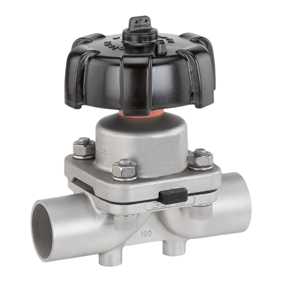
- Page 1 Membranventil Metall, DN 15 - 50 Diaphragm Valve Metal, DN 15 - 50 ORIGINAL EINBAU- UND MONTAGEANLEITUNG INSTALLATION, OPERATING AND MAINTENANCE INSTRUCTIONS 673_us...
-
Page 2: Table Of Contents
Inhaltsverzeichnis Allgemeine Hinweise Allgemeine Hinweise Voraussetzungen für einwandfreie Allgemeine Sicherheitshinweise 2 Funktion des GEMÜ-Ventils: Hinweise für Service- Sachgerechter Transport und Lagerung. und Bedienpersonal Installation und Inbetriebnahme durch Warnhinweise eingewiesenes Fachpersonal. Verwendete Symbole Bedienung gemäß dieser Einbau- und Begriff sbestimmungen Montageanleitung. Vorgesehener Einsatzbereich Ordnungsgemäße Instandhaltung. -
Page 3: Hinweise Für Service
Hinweise für Service- Warnhinweise und Bedienpersonal Warnhinweise sind, soweit möglich, nach folgendem Schema gegliedert: Die Einbau- und Montageanleitung enthält grundlegende Sicherheitshinweise, die bei SIGNALWORT Inbetriebnahme, Betrieb und Wartung zu be- achten sind. Nichtbeachtung kann zur Folge Art und Quelle der Gefahr haben: ®... -
Page 4: Verwendete Symbole
Verwendete Symbole Vorgesehener Einsatzbereich Das GEMÜ-Membranventil 673 ist für Gefahr durch heiße Oberfl ächen! den Einsatz in Rohrleitungen konzipiert. Es steuert ein durchfl ießendes Medium durch Handbetätigung. Gefahr durch ätzende Stoff e! Das Ventil darf nur gemäß den technischen Daten eingesetzt werden Quetschgefahr! (siehe Kapitel 5 "Technische Daten"). - Page 5 Temperaturen Medientemperatur FKM (Code 4/4A) -10 ... 90 °C EPDM (Code 13/3A) -10 ... 100 °C EPDM (Code 17) -10 ... 100 °C EPDM (Code 19) -10 ... 100 °C EPDM (Code 36) -10 ... 100 °C PTFE/EPDM (Code 54) -10 ...
-
Page 6: Bestelldaten
Bestelldaten Ventiltyp Code Ventilkörperwerkstoff Code GEMÜ 673 Membrangröße 25 - 50 EN-GJS-400-18-LT (GGG 40.3) PFA-Auskleidung EN-GJS-400-18-LT (GGG 40.3) PP-Auskleidung 1.4435, Feinguss Gehäuseform Code 1.4408, Feinguss Behälterkörper 1.4435 (316L), Schmiedekörper Durchgang 1.4435 (BN2), Schmiedekörper Δ Fe<0,5% T-Körper 1.4539, Schmiedekörper * Abmessungen siehe Broschüre T-Ventile ** Abmessungen und Ausführungen auf Anfrage... - Page 7 Innenoberfl ächengüten für Schmiede- und Vollmaterialkörper Mechanisch poliert Elektropoliert Medienberührte Hygieneklasse Hygieneklasse Innenoberfl ächen Code Code DIN 11866 DIN 11866 Ra ≤ 0,80 μm 1502 1503 Ra ≤ 0,60 μm 1507 1508 Ra ≤ 0,40 μm 1536 1537 Ra ≤ 0,25 μm 1527 1516 Mechanisch poliert...
-
Page 8: Herstellerangaben
Herstellerangaben Funktionsbeschreibung GEMÜ 673 ist ein Metall-Membranventil mit Durchgangs-, T- oder Behälterboden-Ablass- Transport körper bzw. Ausführung in Mehrwegeausfüh- Membranventil nur auf geeignetem rung. Antriebsgehäuse und -mechanik sind Lademittel transportieren, nicht stürzen, komplett aus Edelstahl. Das Ventil verfügt vorsichtig handhaben. serienmäßig über eine Schließbegrenzung... -
Page 9: Montage Und Bedienung
10 Montage und Bedienung Installationsort: Vor Einbau: VORSICHT Ventilkörper- und Membranwerkstoff Ventil äußerlich nicht stark beanspruchen. entsprechend Betriebsmedium auslegen. Installationsort so wählen, dass Ventil Eignung vor Einbau prüfen! nicht als Steighilfe genutzt werden kann. Siehe Kapitel 5 "Technische Daten". Rohrleitung so legen, dass Schub- und Biegungskräfte, sowie Vibrationen 10.1 Montage des und Spannungen vom Ventilkörper... -
Page 10: Bedienung
Montage bei Clampanschluss: Nach der Montage: Bei Montage der Clampanschlüsse Alle Sicherheits- und Schutzeinrichtungen entsprechende Dichtung zwischen wieder anbringen bzw. in Funktion setzen. Ventilkörper und Rohranschluss einlegen und mit Klammer verbinden. Die Dichtung 10.2 Bedienung sowie die Klammer der Clampanschlüsse sind nicht im Lieferumfang enthalten. -
Page 11: Einstellung Der Schließbegrenzung
Einstellung der Schließbegrenzung nur bei komplett montiertem Ventil (mit Membrane und Ventilkörper) und in kaltem Zustand! Zum Schutz der Dichtmembrane verfügen die Ventile der Baureihe GEMÜ 673 serien- mäßig über eine mechanisch einstellbare Schließbegrenzung. 5. Gewindespindel entsprechend den Ein- Standardeinstellung:... -
Page 12: Montage / Demontage Von Ersatzteilen
ben bis die Unterseite des Einstellrings 4 2. Antrieb A vom Ventilkörper 1 demontieren. stirnseitig auf dem Ventilantrieb anliegt. 3. Antrieb A in Geschlossen-Position bringen. Wichtig: Nach Demontage alle Teile von Ver- schmutzungen reinigen (Teile dabei nicht beschädigen). Teile auf Be- schädigung prüfen, ggf. - Page 13 11.3.2 Montage der Wichtig: Konkav-Membrane Ist die Membrane nicht weit genug in das Verbindungsstück einge- Druckstückaussparung schraubt, wirkt die Schließkraft direkt auf den Schraubpin und nicht Schraubpin über das Druckstück. Das führt zu Beschädigungen und frühzeitigem Ausfall der Membrane und Undicht- heit des Ventils.
-
Page 14: Montage Antrieb Auf Ventilkörper
11.3.3 Montage der 11.4 Montage Antrieb Konvex-Membrane auf Ventilkörper 1. Antrieb A in Geschlossen-Position 1. Antrieb A in Geschlossen-Position bringen. bringen. 2. Neues Membranschild von Hand 2. Antrieb A ca. 20% öff nen. umklappen; bei großen Nennweiten 3. Alle Teile von Produktresten und saubere, gepolsterte Unterlage Verschmutzungen reinigen. -
Page 15: Inbetriebnahme
12 Inbetriebnahme 13 Inspektion und Wartung WARNUNG WARNUNG Aggressive Chemikalien! Unter Druck stehende Armaturen! ® Verätzungen! ® Gefahr von schwersten Verletzungen Vor Inbetriebnahme Dichtheit oder Tod! der Medienanschlüsse Nur an druckloser Anlage arbeiten. prüfen! Dichtheitsprüfung nur mit ge- VORSICHT eigneter Schutzausrüstung. Heiße Anlagenteile! ®... -
Page 16: Demontage
14 Demontage 17 Hinweise Demontage erfolgt unter den gleichen Hinweis zur Richtlinie 94/9/EG Vorsichtsmaßnahmen wie die Montage. (ATEX Richtlinie): Membranventil demontieren (siehe Ein Beiblatt zur Richtlinie 94/9/EG Kapitel 11.1 "Demontage Ventil (Antrieb liegt dem Produkt bei, sofern es vom Körper lösen)"). gemäß... -
Page 17: Fehlersuche / Störungsbehebung
18 Fehlersuche / Störungsbehebung Fehler Möglicher Grund Fehlerbehebung Medium entweicht aus Absperrmembrane auf Beschädigungen Absperrmembrane defekt Leckagebohrung* prüfen, ggf. Membrane tauschen Antrieb defekt Antrieb austauschen Ventil öff net nicht bzw. nicht Absperrmembrane nicht korrekt Antrieb demontieren, Membranmontage vollständig montiert prüfen, ggf. austauschen Ventil mit Betriebsdruck laut Datenblatt Betriebsdruck zu hoch betreiben... -
Page 18: Schnittbild Und Ersatzteile
19 Schnittbild und Ersatzteile Leckagebohrung Pos. Benennung Bestellbezeichnung Ventilkörper K600... Membrane 600...M Schraube Scheibe 673...S30... Mutter Antrieb 9673... 673_us 18 / 44... - Page 19 GEMÜ Gebr. Müller GmbH & Co. KG Fritz-Müller-Straße 6-8 D-74653 Ingelfi ngen erklären, dass unten aufgeführte Armaturen die Sicherheitsanforderungen der Druckgeräte- richtlinie 97/23/EG erfüllen. Benennung der Armaturen - Typenbezeichnung Membranventil GEMÜ 673 Benannte Stelle: TÜV Rheinland Berlin Brandenburg Nummer: 0035 Zertifi kat-Nr.: 01 202 926/Q-02 0036 Konformitätsbewertungsverfahren:...
- Page 20 Notizen 673_us 20 / 44...
- Page 21 Contents General notes General notes Prerequisites for the correct functioning of General safety notes the GEMÜ valve: Notes for servicing and Proper transport and storage. operating personnel Installation and commissioning by trained Warning notes specialist staff . Symbols used Operation according to these installation, Defi...
-
Page 22: Notes For Servicing And Operating Personnel
Notes for servicing and In case of uncertainty operating personnel Consult the nearest GEMÜ sales offi ce. The installation, operating and maintenance instructions contain fundamental safety Warning notes notes that must observed during Wherever possible, warning notes are commissioning, operation and serving. organised according to the following scheme: Non-observance can cause: SIGNAL WORD... -
Page 23: Symbols Used
Symbols used Limited use Danger - hot surfaces! The GEMÜ 673 diaphragm valve is designed for installation in piping systems. It controls a fl owing medium by Danger - corrosive materials! manual operation. The valve may only be used providing... -
Page 24: Technical Data
Technical data Working medium Corrosive, inert, gaseous and liquid media which have no negative impact on the physical and chemical properties of the body and diaphragm material. Temperatures Media temperature FKM (Code 4/4A) 14 ... 194 °F EPDM (Code 13/3A) 14 ... -
Page 25: Order Data
GEMÜ 612 diaphragm size 10 Flanges EN 1092 / PN16 / form B, length EN 558, series 1, GEMÜ 673 diaphragm size 25 - 50 ISO 5752, basic series 1 Flanges ANSI Class 150 RF, length MSS SP-88 Body confi guration... - Page 26 Valve body material Code Bonnet version Code EN-GJS-400-18-LT (SG iron 40.3) PFA lined With seal adjuster, black handwheel GEMÜ 673 diaphragm size 25 EN-GJS-400-18-LT (SG iron 40.3) PP lined With seal adjuster, black handwheel 1.4435, investment casting GEMÜ 673 diaphragm size 40 1.4408, investment casting...
- Page 27 Internal surface fi nishes for investment cast bodies Mechanically polished Readings for Process Hygienic class Contact Surfaces Code DIN 11866 Ra ≤ 6,30 μm 1500 Ra ≤ 0,80 μm 1502 Ra ≤ 0,60 μm 1507 Surface fi nishes of customized valve bodies may be limited in special cases. Or any other fi...
-
Page 28: Manufacturer's Information
Manufacturer’s information Function description GEMÜ 673 is a metal diaphragm valve with a 2/2-way, T or tank bottom valve body or in Transport multi-port design. Bonnet and internals are made all of stainless steel. An integral optical Only transport the diaphragm valve... -
Page 29: Assembling The Diaphragm Valve
10.1 Assembling the Installation location: diaphragm valve CAUTION Do not apply external force to the valve. WARNING Choose the installation location so that The equipment is subject to the valve cannot be used as a foothold. pressure! Lay the pipeline so that the valve body ®... -
Page 30: Operation
Assembly - Clamp connections: Observe appropriate regulations for connections! When assembling clamp connections, insert a gasket between the body clamp and the adjacent After the assembly: piping clamp and join them using the Reactivate all safety and protective appropriate clamp fi tting. The gasket and devices. -
Page 31: Setting The Seal Adjuster
Only set the seal adjuster when the valve is completely assembled (with diaphragm and valve body) and in a cold condition! The valves type GEMÜ 673 have a mechanical seal adjuster as standard to protect the sealing diaphragm. Standard setting: The valve is sealed when the handwheel is 5. -
Page 32: Assembly / Disassembly Of Spare Parts
spindle until the bottom side of the adjusting 2. Remove bonnet A from valve body 1. ring 4 sits on the face of the valve bonnet. 3. Move bonnet A to the closed position. Important: After disassembly, clean all parts of contamination (do not damage parts). - Page 33 11.3.2 Mounting a Important: concave diaphragm If the diaphragm is not screwed into the adapter far enough, the closing Recess of compressor force is transmitted directly onto the threaded pin and not via the Threaded pin compressor. This will cause damage and early failure of the diaphragm and thus leakage of the valve.
-
Page 34: Bonnet Mounting On The Valve Body
11.4 Bonnet mounting compressor. on the valve body Adapter Recess of compressor Compressor 1. Move bonnet A to the closed position. 2. Open bonnet A approx. 20 %. 3. Clean all parts of the remains of product and contamination. Do not scratch or damage parts during cleaning! Backing 4. -
Page 35: Commissioning
12 Commissioning 13 Inspection and servicing WARNING WARNING Corrosive chemicals! The equipment is subject to pressure! ® Risk of caustic burns! ® Risk of severe injury or death! Check the tightness of the Only work on depressurized plant. media connections prior to commissioning! WARNING Use only the appropriate... -
Page 36: Disassembly
14 Disassembly 17 Information Note on Directive 94/9/EC Disassembly is performed observing the (ATEX Directive): same precautionary measures A supplement to Directive 94/9/EC assembly. is included with the product if it was Disassemble the diaphragm valve ordered according to ATEX. (see chapter 11.1 "Valve disassembly (removing bonnet from body)"). -
Page 37: Troubleshooting / Fault Clearance
Troubleshooting / Fault clearance Fault Possible cause Fault clearance Medium escapes from leak Check valve diaphragm for damage, Valve diaphragm faulty detection hole* replace diaphragm if necessary Bonnet faulty Replace bonnet Valve doesn't open or Remove bonnet, check diaphragm doesn't open fully Valve diaphragm incorrectly mounted mounting, replace if necessary Operate valve with operating pressure... -
Page 38: Sectional Drawing And
19 Sectional drawing and spare parts Leak detection hole Item. Name Order description Valve body K600... Diaphragm 600...M Bolt Washer 673...S30... Bonnet 9673... 673_us 38 / 44... - Page 39 D-74653 Ingelfi ngen declare that the equipment listed below complies with the safety requirements of the Pressure Equipment Directive 97/23/EC. Description of the equipment - product type Diaphragm Valve GEMÜ 673 Notifi ed body: TÜV Rheinland Berlin Brandenburg Number: 0035 Certifi...
- Page 40 Notes 673_us 40 / 44...
- Page 41 673_us 41 / 44...
- Page 42 Rücksendeerklärung (Kopiervorlage) Gesetzliche Bestimmungen, der Schutz der Umwelt und des Personals erfordern es, diese Erklärung vollständig ausgefüllt und unterschrieben den Versandpapieren beizulegen. Wenn diese Erklärung nicht vollständig ausgefüllt ist oder den Versandpapieren nicht beigelegt ist wird Ihre Rücksendung nicht bearbeitet! Wurde das Ventil / Gerät mit giftigen, ätzenden, brennbaren, aggressiven oder wassergefährdenden Medien betrieben, alle mediumsberührten Teile sorgfältig entleeren, dekontaminieren und spülen.
- Page 43 Goods return declaration (copy specimen) Legal regulations for the protection of the environment and personnel require that you include the completed and signed goods return declaration with your dispatch documents. If this declaration is not completed or not included with the dispatch documents, your return will not be processed! If the valve / device was operated with poisonous, corrosive, flammable, aggressive or water- endangering media, all medium wetted parts must be emptied carefully, decontaminated and rinsed.
- Page 44 VENTIL-, MESS- UND REGELSYSTEME VALVES, MEASUREMENT AND CONTROL SYSTEMS GEMÜ Gebr. Müller Apparatebau GmbH & Co. KG · Fritz-Müller-Str. 6-8 · D-74653 Ingelfi ngen-Criesbach Telefon +49(0)7940/123-0 · Telefax +49(0)7940/123-192 · info@gemue.de ·www.gemue.de...
Need help?
Do you have a question about the 673 and is the answer not in the manual?
Questions and answers