Table of Contents
Advertisement
Quick Links
Industrial
Wireless Access Point
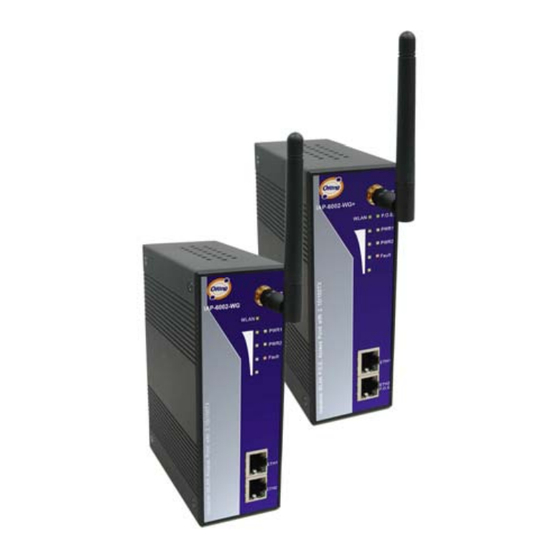
IAP-6002-WA / WA+ User's Manual
Version 1.0
May, 2008.
ORing Industrial Networking Corp.
4F, NO.3, Lane235, Baociao Rd. Sindian City,
Taipei County 23145 Taiwan, R.O.C.
Tel: + 886 2 2918 3036
Fax: + 886 2 2918 3084
Website: www.oring-networking.com
E-mail:
support@oring-networking.com
Advertisement
Table of Contents

Related Manuals for ORiNG IAP-6002-WA


Summary of Contents for ORiNG IAP-6002-WA
- Page 1 Industrial Wireless Access Point IAP-6002-WA / WA+ User’s Manual Version 1.0 May, 2008. ORing Industrial Networking Corp. 4F, NO.3, Lane235, Baociao Rd. Sindian City, Taipei County 23145 Taiwan, R.O.C. Tel: + 886 2 2918 3036 Fax: + 886 2 2918 3084 Website: www.oring-networking.com...
-
Page 2: Table Of Contents
Table of Content Getting to Know Your Access Point ............1 About the ORing Access Point ................. 1 Software Features ....................1 Hardware Features....................1 Hardware Installation..................2 Installation AP on DIN-Rail ..................2 Wall Mounting Installation ..................3 Hardware Overview..................5 Front Panel....................... - Page 3 Setting DHCP Server....................26 5.5.2 Advanced Setting....................27 Wireless ........................27 MAC Filter........................29 System Event......................29 Email Settings......................30 SNMP Settings ......................31 Syslog Server Settings ....................31 5.5.3 System Tools...................... 32 Administrator....................... 32 Date & Time ........................ 33 Configuration ......................
-
Page 4: Getting To Know Your Access Point
Switch Mode Supported: Daisy Chain support to reduce usage of switch ports Secured Management by HTTPS Event Warning by Syslog, Email, SNMP Trap, Relay and Beeper Hardware Features Fully Compliant with IEEE802.3af (Power Device at ETH2, IAP-6002-WA+ only) Redundant Power Inputs: 12~48 VDC on terminal block 10/100Base-T(X) Ethernet port Casing: IP-30... -
Page 5: Hardware Installation
IAP-6002-WA / WA+ User’s Manual ardware Installation Installation AP on DIN-Rail Each AP has a DIN-Rail kit on rear panel. The DIN-Rail kit helps AP to fix on the DIN-Rail. It is easy to install the AP on the DIN-Rail: Step 1: Slant the AP and mount the metal spring to DIN-Rail. -
Page 6: Wall Mounting Installation
IAP-6002-WA / WA+ User’s Manual Wall Mounting Installation Each AP has another installation method to fix the AP. A wall mount panel can be found in the package. The following steps show how to mount the AP on the wall: Step 1: Remove DIN-Rail kit. - Page 7 IAP-6002-WA / WA+ User’s Manual The screws specification shows in the following two pictures. In order to prevent the AP from any damage, the screws should not larger than the size that used in IAP-6002-WA / WA+. Pozidrive Step 3: Mount the combined AP on the wall.
-
Page 8: Hardware Overview
IAP-6002-WA / WA+ User’s Manual ardware Overview Front Panel The following table describes the labels that stick on the IAP-6002-WA / WA+. Port Description 2 10/100Base-T(X) RJ-45 fast Ethernet ports support 10/100 RJ-45 fast Ethernet ports auto-negotiation. Default Setting : Speed: auto P.O.E. - Page 9 4. LED for PWR2 and system status. When the PWR2 links, the green LED will be light 5. LED for Fault Relay. When the fault occurs, the amber LED will be light on. 6. 10/100Base-T(X) Ethernet ports. (IAP-6002-WA+ contains PD function of P.O.E.) 7. LED for Ethernet ports status.
-
Page 10: Front Panel Leds
IAP-6002-WA / WA+ User’s Manual Front Panel LEDs Color Status Description Green On P.O.E. power connected. Green blinking Device been located P.O.E. Green/Red Indicates an IP conflict, or (IAP-6002-WA+) Red blinking DHCP or BOOTP server did not respond properly Green On DC power 1 activated. -
Page 11: Bottom Panel
IAP-6002-WA / WA+ User’s Manual Bottom Panel The bottom panel components of IAP-6002-WA / WA+ are showed as below: 1. Terminal block includes: PWR1, PWR2 (12 ~ 48V DC) and Relay output (1A@24VDC). 2. Reset bottom. Push the bottom 3 seconds for reset; 5 seconds for factory default. -
Page 12: Cables And Antenna
Ethernet Cables The IAP-6002-WA / WA+ WLAN AP have standard Ethernet ports. According to the link type, the AP use CAT 3, 4, 5,5e UTP cables to connect to any other network device (PCs, servers, switches, routers, or hubs). Please refer to the following table for cable specifications. -
Page 13: Wireless Antenna
Note: “+” and “-” signs represent the polarity of the wires that make up each wire pair. Wireless Antenna A 2.4GHz antenna is used for IAP-6002-WA / WA+ and connected with a reversed SMA connector. External antenna also can be applied with this connector. -
Page 14: Management Interface
Explore IAP-6002-WA / WA+ 5.1.1 AP-Tool software Each model contains friendly software, AP-Tool, to explore IAP-6002-WA / WA+ on local area network. Step 1: Open the AP tool and click “Refresh list”, the AP devices will show on the list. -
Page 15: Upnp Equipment
IAP-6002-WA / WA+ User’s Manual UPnP Equipment Step 1: To check whether the UPnP UI of the computer is connected to the IAP-6002-WA / WA+, go to Control Panel > Add or Remove Programs > Windows Components Wizard > Networking Servers > UPnP User Interface and pitch on the UPnP User Interface. -
Page 16: Configuration By Web Browser
IAP-6002-WA / WA+ User’s Manual Step 3: Click the sign of the UPnP equipment, then you will find the UPnP equipment in the network neighborhood. Step 4: Right click the UPnP equipment to choose “Properties”, it will show as the following pictures: Step 5: Right click the UPnP equipment or double click the UPnP equipment to transfer;... -
Page 17: About Web-Based Management
IAP-6002-WA / WA+ User’s Manual About Web-based Management An embedded HTML web site resides in flash memory in the system. It contains advanced management features and allows you to manage the AP from anywhere on the network through a standard web browser such as Microsoft Internet Explorer. -
Page 18: Basic Setting
IAP-6002-WA / WA+ User’s Manual Main interface 5.5.1 Basic Setting Setting Operation Mode Operation mode interface The following table describes the labels in this screen. Label Description Bridge This mode provides Static LAN-to-LAN Bridging functionality. The static LAN-to-LAN bridging function is supported through Wireless Distribution System (WDS). -
Page 19: Setting Wds (Bridge Mode)
IAP-6002-WA / WA+ User’s Manual In each mode, the IAP-6002-WA / WA+ forwards packet between its Ethernet interface and wireless interface for wired hosts on the Ethernet side, and wireless hosts on the wireless side. Setting WDS (Bridge Mode) WDS setting interface This type of wireless link is established between two IEEE 802.11 access points. - Page 20 IAP-6002-WA / WA+ User’s Manual Point-to-Point WDS Link The following table describes the labels in this screen. Label Description WDS Mode This mode provides Static LAN-to-LAN Bridging functionality. The static LAN-to-LAN bridging function is supported through Wireless Distribution System (WDS).
- Page 21 IAP-6002-WA / WA+ User’s Manual WDS – Restricted Mode The peer WDS APs are according to the MAC address listed in "Peer Mac Address" fields. WDS –Bridge Mode Same as Restrict mode in functionality and also one WDS link side can not set Peer Mac Address 1-4.
- Page 22 IAP-6002-WA / WA+ User’s Manual The working principle of Bridge Mode as follows: In the figure, the AP behaves as a standard bridge that forwards traffic between WDS links (links that connect to other AP/wireless bridges) and an Ethernet port. As a standard bridge,...
-
Page 23: Setting Wireless
IAP-6002-WA / WA+ User’s Manual Same as Restrict mode in functionality and also one WDS link side can not set Peer Mac Address 1-4. The working principle of Repeater Mode as follows: In the figure, Repeater is used to extend the range of the wireless infrastructure by forwarding traffic between associated wireless stations and another repeater or AP connected to the wired LAN. - Page 24 IAP-6002-WA / WA+ User’s Manual The following table describes the labels in this screen. Label Description Service Set Identifier Default is the default setting. The SSID is a unique name that identifies a network. All devices on the network must share the same SSID name in order to SSID communicate on the network.
- Page 25 IAP-6002-WA / WA+ User’s Manual Security Type – WEP Security Type: Select WEP WEP Encryption: Select 64 Bit or 128 Bit WEP encryption. Key Type: Select ASCII or Hex key type. Default Key Index: Select one of the keys to be the active key.
- Page 26 IAP-6002-WA / WA+ User’s Manual Security Type – WPA-PSK/WPA2-PSK 1. Security Type: Select WPA-PSK/WPA2-PSK. 2. Encryption Type: Select TKIP or AES encryption. 3. Share Key: Enter your password. The password can be between 8 and 64 characters. Security Type – WPA /WPA2 1.
-
Page 27: Lan Setting
IAP-6002-WA / WA+ User’s Manual RADIUS (Remote Authentication Dial-in User Service) is the industrial standard agreement, and it is used to provide an identify verification. The Radius customer (is usually a dial-in server, VPN server or wireless point) send your proof and the conjunction parameter to the Radius server by Radius news. - Page 28 Obtain an IP address Select this option if you would like to have an IP address automatically automatically assigned to the IAP-6002-WA / WA+ by DHCP server in your network Select this option if you are manually assigning an IP address.
-
Page 29: Setting Dhcp Server
IP will not been occupied for a long time or the server doesn’t know that the dynamic IP is idle. List the devices on your network that are receiving dynamic IP DHCP Clients List addresses from the IAP-6002-WA / WA+. ORing Industrial Networking Corp. -
Page 30: Advanced Setting
IAP-6002-WA / WA+ User’s Manual 5.5.2 Advanced Setting Wireless The following table describes the labels in this screen. Label Description The default value is 100. The Beacon Interval value indicates Beacon Interval the frequency interval of the beacon. A beacon is a packet broadcast by the AP to synchronize the wireless network. - Page 31 IAP-6002-WA / WA+ User’s Manual RTS Threshold This value should remain at its default setting of 2347. The range is 0-2347 bytes. Should you encounter inconsistent data flow, only minor modifications are recommended. If a network packet is smaller than the preset RTS threshold size, the RTS/CTS mechanism will not be enabled.
-
Page 32: Mac Filter
Use Advanced Setting > MAC Filters to allow or deny wireless clients, by their MAC addresses, from accessing the IAP-6002-WA / WA+. You can manually add a MAC address or select the MAC address from Connected Clients that are currently connected to the AP. -
Page 33: Email Settings
IAP-6002-WA / WA+ User’s Manual System events record the activities of the AP system. When the setting changes or action performs, the event will be sent to administrator by email. A trap will also be sent to SNMP server. The Syslog will record the event locally and may send the log remotely to a Syslog server. -
Page 34: Snmp Settings
IAP-6002-WA / WA+ User’s Manual Server Port Specify the port where MTA can be contacted via SMTP server. E-mail Address 1-4 Inputs specify the destination mail address. SNMP Settings The following table describes the labels in this screen. Label Description... -
Page 35: 5.5.3 System Tools
IAP-6002-WA / WA+ User’s Manual The following table describes the labels in this screen. Label Description Syslog Server IP Not only the syslog keeps the logs locally, it can also log to remote server. Specify the IP of remote server. Leave it blank to disable logging remotely. -
Page 36: Date & Time
IAP-6002-WA / WA+ User’s Manual '0-9', 'a-z', 'A-Z' and must be between 1 to 15 characters in length. This field can not accept null input. New Password Enter a new login password. Acceptable inputs of this field contains '0-9', 'a-z', 'A-Z' and must be between 0 to 15 characters in length. - Page 37 IAP-6002-WA / WA+ User’s Manual The following table describes the labels in this screen. Label Description Local Date Set local date manually. Local Time Set local time manually. Time Zone Select the time zone manually Get Current Date & Click this button, you can set the time from browser.
-
Page 38: Configuration
Click Upload when you have selected the file to be loaded back onto the AP. Restore Default You may also reset the IAP-6002-WA / WA+ back to factory Settings settings by clicking on Restore Default Settings. Make sure to save the unit’s settings before clicking on this button. -
Page 39: Miscellaneous
IAP-6002-WA / WA+ User’s Manual minutes to upload and upgrade the firmware. After the upgrade is done successfully, the access point will reboot and get revalidated. Notice: DO NOT POWER OFF THE AP OR PRESS THE RESET BUTTON WHILE THE FIRMWARE IS BEING UPGRADED. -
Page 40: 5.5.4 System Status
IAP-6002-WA / WA+ User’s Manual 5.5.4 System Status System Info This page displays the current information for the IAP-6002-WA / WA+. It will display model name, as well as firmware version, Ethernet, Wireless info and device time. System Log The system log tracks the important events and setting changes of the AP. If the AP is rebooted, the logs are automatically cleared. -
Page 41: Traffic Statistics
IAP-6002-WA / WA+ User’s Manual Traffic Statistics This page displays the network traffic statistics for both received and transmitted packets through the Ethernet port and wireless connections associated with the AP. Simultaneity, the traffic counter will reset by the device rebooting. -
Page 42: 5.5.5 Online Help
IAP-6002-WA / WA+ User’s Manual 5.5.5 Online Help Click on any item in the Online Help screen for more information. ORing Industrial Networking Corp. -
Page 43: Technical Specifications
IAP-6002-WA / WA+ User’s Manual echnical pecifications LAN Interface RJ45 Ports 2 x 10/100Base-T(X), Auto MDI/MDI-X P.O.E. PD (Power Device) Present at ETH2 of IAP-6002-WA+ ETH2 act as Power Device (IEEE802.3af): IEEE 802.3af compliant input interface Power consumption: 8Watts max. - Page 44 TKIP encryption Wireless Security SSID broadcast disable LED Indicators PWR 1(2) (P.O.E., IAP-6002-WA+) / Ready: 1) Red On: Power is on and booting up. 2) Green On: Power is on and functioning normally. ETH1 (2) Link / ACT: Orange ON/Blinking: 10 Mbps Ethernet...
Need help?
Do you have a question about the IAP-6002-WA and is the answer not in the manual?
Questions and answers