Table of Contents
Advertisement
Quick Links
I
E
E
E
I
E
E
E
1
I
A
P
-
6
2
0
I
A
P
-
6
2
0
8
0
2
.
1
1
a
/
b
/
g
/
8
0
2
.
1
1
a
/
b
/
g
U
s
e
r
'
s
M
U
s
e
r
'
s
M
V
e
r
s
i
o
n
V
e
r
s
i
o
n
J
u
l
y
,
2
J
u
l
y
,
2
IAP-620 Series User's Manual
S
e
r
i
e
s
S
e
r
i
e
s
n
A
c
c
e
s
s
P
o
/
n
A
c
c
e
s
s
P
o
a
n
u
a
l
a
n
u
a
l
1
.
0
1
.
0
0
1
2
0
1
2
w
w
w
.
o
r
i
n
g
w
w
w
.
o
r
i
n
g
ORing Industrial Networking Corp.
i
n
t
i
n
t
-
n
e
t
w
o
r
k
i
n
g
.
c
o
m
-
n
e
t
w
o
r
k
i
n
g
.
c
o
m
Advertisement
Table of Contents

Subscribe to Our Youtube Channel
Related Manuals for ORiNG IAP-620 Series


Summary of Contents for ORiNG IAP-620 Series
- Page 1 IAP-620 Series User’s Manual ’ ’ ORing Industrial Networking Corp.
-
Page 2: Contact Information
ORing warrants that all ORing products are free from defects in material and workmanship for a specified warranty period from the invoice date (5 years for most products). ORing will repair or replace products found by ORing to be defective within this warranty period, with shipment expenses apportioned by ORing and the distributor. -
Page 3: Table Of Contents
IAP-620 Series User’s Manual Table of Content Getting to Know Your Access Point ............5 About the ORing Access Point ..................5 Software Features ......................5 Hardware Features ......................5 Hardware Installation ..................6 ... - Page 4 IAP-620 Series User’s Manual 5.5.2 Advanced Setting ......................31 Wireless ............................ 31 X-Roaming ..........................33 MAC Filter ..........................33 System Event ..........................34 Email Settings .......................... 35 SNMP Settings ......................... 36 ...
-
Page 5: Getting To Know Your Access Point
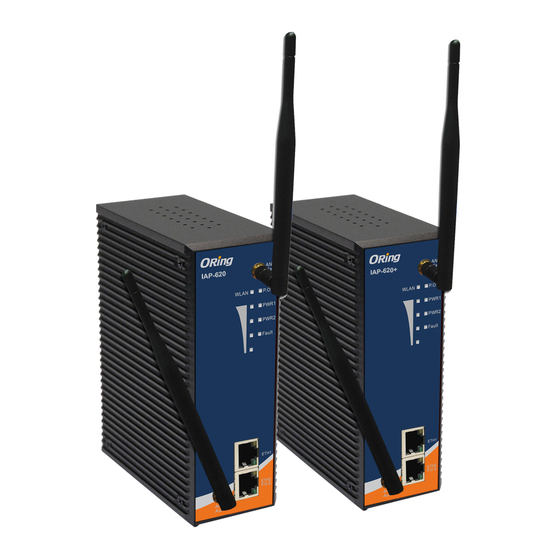
IAP-620 Series User’s Manual etting to Know Your Access Point 1.1 About the ORing Access Point IAP-620/IAP-620+ is reliable IEEE802.11a/b/g/n WLAN with 2 ports LAN Access Point. It can be configured to operate in AP/Client/Bridge/AP-Client mode. configure IAP-620/IAP-620+ by Windows Utility or WEB interfaces via LAN port or WLAN interface. -
Page 6: Hardware Installation
IAP-620 Series User’s Manual ardware Installation Installation AP on DIN-Rail Each AP has a DIN-Rail kit on rear panel. The DIN-Rail kit helps AP to fix on the DIN-Rail. It is easy to install the AP on the DIN-Rail: Step 1: Slant the AP and mount the metal spring to DIN-Rail. -
Page 7: Wall Mounting Installation
IAP-620 Series User’s Manual Wall Mounting Installation Each AP has another installation method to fix the AP. A wall mount panel can be found in the package. The following steps show how to mount the AP on the wall: Step 1: Remove DIN-Rail kit. - Page 8 IAP-620 Series User’s Manual The screws specification shows in the following two pictures. In order to prevent the AP from any damage, the screws should not larger than the size that used in IAP-620 / 620+. Pozidrive Step 3: Mount the combined AP on the wall.
-
Page 9: Hardware Overview
IAP-620 Series User’s Manual ardware Overview Front Panel The following table describes the labels that stick on the IAP-620/IAP-620+. Port Description 2 10/100Base-T(X) RJ-45 fast Ethernet ports support 10/100 RJ-45 fast Ethernet ports auto-negotiation. Default Setting : Speed: auto PoE P.D. Port ETH2 of IAP-620+ compliant with IEEE802.3af PoE specifications... - Page 10 IAP-620 Series User’s Manual IAP-620 IAP-620+ 2.4/5 GHz antenna with typical 3.0 dBi antenna. LED for PoE power and system status. When the PoE power links, the green LED will be light on. LED for PWR1 and system status. When the PWR1 links, the green LED will be light LED for PWR2 and system status.
-
Page 11: Front Panel Leds
IAP-620 Series User’s Manual Front Panel LEDs Color Status Description Green On PoE power connected. Green blinking Device been located P.O.E. Green/Red Indicates an IP conflict, or (IAP-620+) Red blinking DHCP or BOOTP server did not respond properly Green On DC power 1 activated. -
Page 12: Bottom Panel
IAP-620 Series User’s Manual Bottom Panel The bottom panel components of IAP-620 / 620+ are showed as below: 1. Terminal block includes: PWR1, PWR2 (12 ~ 48V DC) and Relay output (1A@24VDC). 2. Reset bottom. Push the button 3 seconds for reset; 5 seconds for factory default. -
Page 13: Cables And Antenna
IAP-620 Series User’s Manual ables and ntenna Ethernet Cables The IAP-620/IAP-620+ WLAN AP has two 10/100Base-T(X) Ethernet ports. According to the link type, the AP use CAT 3, 4, 5,5e UTP cables to connect to any other network device (PCs, servers, switches, routers, or hubs). Please refer to the following table for cable specifications. -
Page 14: Wireless Antenna
IAP-620 Series User’s Manual MDI/MDI-X pins assignment Pin Number MDI port MDI-X port TD+(transmit) RD+(receive) TD-(transmit) RD-(receive) RD+(receive) TD+(transmit) P.O.E. power input + P.O.E. power input + P.O.E. power input + P.O.E. power input + RD-(receive) TD-(transmit) P.O.E. power input - P.O.E. -
Page 15: Management Interface
Explore IAP-620/IAP-620+ 5.1.1 Open-Vision_Commander IAP-620/IAP-620+ can also be configure through ORing’s Windows utility Open-Vision Step 1: Open the commander and click “Discover”, the AP devices will show on the list. Step 2: Choose your access point, and it will show the AP function tree. Simultaneity, you can login and then set the AP. -
Page 16: Upnp Equipment
IAP-620 Series User’s Manual UPnP Equipment Step 1: To check whether the UPnP UI of the computer is connected to the IAP-620/IAP-620+, go to Control Panel > Add or Remove Programs > Windows Components Wizard > Networking Servers > UPnP User Interface and pitch on the UPnP User Interface. -
Page 17: Configuration By Web Browser
IAP-620 Series User’s Manual Step 3: Click the sign of the UPnP equipment, then you will find the UPnP equipment in the network neighborhood. Step 4: Right click the UPnP equipment to choose “Properties”, it will show as the following pictures: Step 5: Right click the UPnP equipment or double click the UPnP equipment to transfer;... -
Page 18: Main Interface
IAP-620 Series User’s Manual the browser setting in order to enable Java Applets to use network ports. Through the front section’s information, you will see as follows, enter your user name (admin) and your password (admin), and then click OK to continue. -
Page 19: Basic Setting
IAP-620 Series User’s Manual 5.5.1 Basic Setting Setting Operation Mode Operation mode interface The following table describes the labels in this screen. Label Description This mode provides Access Point services for other wireless clients. AP-Client The AP-Client function provides a 1-to-N MAC address mapping mechanism such that multiple stations behind the AP can transparently connect to the other AP even they didn’t support... -
Page 20: Setting Wds (Bridge Mode)
IAP-620 Series User’s Manual Setting WDS (Bridge Mode) WDS setting interface This type of wireless link is established between two IEEE 802.11 access points. Wireless packets transmitted along the WDS link comply with the IEEE 802.11 WDS (Wireless Distribution System) format at the link layer. - Page 21 IAP-620 Series User’s Manual 2. All AP’s DHCP Server should set shutdown. 3. WDS should set Enable. 4. Each AP should have the same setting except ‘Peer Mac Address’ set to the other’s Mac address 5. At wireless web setting Security and Channel should be the same, 6.
- Page 22 IAP-620 Series User’s Manual WDS –Repeater Mode The peer WDS APs are according to the MAC address listed in "Peer Mac Address" fields. The working principle of Repeater Mode as follows: In the figure, Repeater is used to extend the range of the wireless infrastructure by forwarding traffic between associated wireless stations and another repeater or AP connected to the wired LAN.
-
Page 23: Setting Wireless
IAP-620 Series User’s Manual Setting Wireless The following table describes the labels in this screen. Label Description Service Set Identifier Default is the default setting. The SSID is a unique name that identifies a network. All devices on the SSID network must share the same SSID name in order to communicate on the network. - Page 24 IAP-620 Series User’s Manual Security Type – None No security protection on your wireless LAN access. Security Type – WEP Security Type: Select WEP WEP Encryption: Select 64 Bit or 128 Bit WEP encryption. Key Type: Select ASCII or Hex key type.
- Page 25 IAP-620 Series User’s Manual Security Type – WPA-PSK/WPA2-PSK 1. Security Type: Select WPA-PSK/WPA2-PSK. 2. Encryption Type: Select TKIP or AES encryption. 3. Share Key: Enter your password. The password can be between 8 and 64 characters. Security Type – WPA /WPA2 1.
- Page 26 IAP-620 Series User’s Manual Security Type – 802.1x 1. Security Type: Select 802.1x 2. WEP Encryption: Select 64 Bit or 128 Bit WEP encryption. 3. Key Type: Select ASCII or Hex key type. 4. Default Key Index: Select one of the keys to be the active key.
- Page 27 IAP-620 Series User’s Manual RADIUS (Remote Authentication Dial-in User Service) is the industrial standard agreement, and it is used to provide an identify verification. The Radius customer (is usually a dial-in server, VPN server or wireless point) send your proof and the conjunction parameter to the Radius server by Radius news.
-
Page 28: Client
IAP-620 Series User’s Manual Client The Basic setting—> Client page is mainly set the client which through the SSID and Security to connect to other AP. In this mode, the Security Type should be the same with the AP Server. -
Page 29: Lan Setting
IAP-620 Series User’s Manual LAN Setting The Basic Setting > LAN Setting page is mainly set IP address for LAN interface. To access the AP normally, a valid IP address of your LAN should be specified to the LAN interface. The default IP setting is DHCP server (Obtain an IP address automatically). -
Page 30: Setting Dhcp Server
IAP-620 Series User’s Manual server addresses Preferred DNS: There is a default DNS server, and you can input another new DNS server. Alternate DNS: There is a default DNS server, and you can input another new DNS server. Setting DHCP Server The following table describes the labels in this screen. -
Page 31: Advanced Setting
IAP-620 Series User’s Manual 5.5.2 Advanced Setting Wireless The following table describes the labels in this screen. Label Description The default value is 100. The Beacon Interval value indicates Beacon Interval the frequency interval of the beacon. A beacon is a packet broadcast by the AP to synchronize the wireless network. - Page 32 IAP-620 Series User’s Manual with a DTIM Interval value. Its clients hear the beacons and awaken to receive the broadcast and multicast messages. Fragmentation This value should remain at its default setting of 2346. The Threshold range is 256-2346 bytes. It specifies the maximum size for a packet before data is fragmented into multiple packets.
-
Page 33: X-Roaming
IAP-620 Series User’s Manual to associate with, they will detect the SSID broadcast by the AP. To broadcast the AP SSID, keep the default setting, Enable. If you do not want to broadcast the AP SSID, then select Disable. Signal Threshold for Roaming signal threshold setting. -
Page 34: System Event
IAP-620 Series User’s Manual The following table describes the labels in this screen. Label Description MAC Filter Enable or disable the function of MAC filter. MAC address allowed or denied option is selected by you. MAC Filter List This list will display the MAC addresses that are in the selected filter. -
Page 35: Email Settings
IAP-620 Series User’s Manual System events record the activities of the AP system. When the setting changes or action performs, the event will be sent to administrator by email. A trap will also be sent to SNMP server. The Syslog will record the event locally and may send the log remotely to a Syslog server. -
Page 36: Snmp Settings
IAP-620 Series User’s Manual The following table describes the labels in this screen. Label Description SMTP Server Simple Message Transfer Protocol, enter the backup host to use if primary host is unavailable while sending mail by SMTP server. Specify the port where MTA can be contacted via SMTP server. -
Page 37: Syslog Server Settings
IAP-620 Series User’s Manual Syslog Server Settings The following table describes the labels in this screen. Label Description Syslog Server IP Not only the syslog keeps the logs locally, it can also log to remote server. Specify the IP of remote server. Leave it blank to disable logging remotely. -
Page 38: System Tools
IAP-620 Series User’s Manual 5.5.3 System Tools Administrator In this page, you can change the username and password. The new password must be typed twice to confirm (the default Name and Password is “admin” and “”). The following table describes the labels in this screen. - Page 39 IAP-620 Series User’s Manual protocol. Port Corresponding to the Web protocol, there is a default port (HTTP: 80, HTTPS: 443). And you can enter another number which should be in range of 1-65535. Choose the checkbox of the Wired and Wireless; you can visit the Web Access Control web page through the mode you choose.
-
Page 40: Date & Time
IAP-620 Series User’s Manual Date & Time In this page, set the date & time of the device. The correct date & time will be helpful for logging of system events. A NTP (Network Time Protocol) client can be used to synchronize date &... -
Page 41: Configuration
IAP-620 Series User’s Manual Configuration The following table describes the labels in this screen. Label Description Download The current system settings can be saved as a file onto the local configuration hard drive. Upload configuration The saved file or any other saved setting file can be uploaded back on the AP. -
Page 42: Firmware Upgrade
IAP-620 Series User’s Manual Firmware Upgrade New firmware may provide better performance, bug fixes or more functions. To upgrade, you need a firmware file correspond to this AP model. It will take several minutes to upload and upgrade the firmware. After the upgrade is done successfully, the access point will reboot and get revalidated. -
Page 43: System Status
IAP-620 Series User’s Manual 5.5.4 System Status System Info This page displays the current information for the IAP-620/IAP-620+. It will display model name, as well as firmware version, Ethernet, Wireless info and device time. ORing Industrial Networking Corp. -
Page 44: System Log
IAP-620 Series User’s Manual System Log The system log tracks the important events and setting changes of the AP. If the AP is rebooted, the logs are automatically cleared. Click the button 'Refresh' to refresh the page; Click the button 'Clear' to clear log entries. -
Page 45: Online Help
IAP-620 Series User’s Manual 5.5.5 Online Help Click on any item in the Online Help screen for more information. ORing Industrial Networking Corp. -
Page 46: Technical Specifications
IAP-620 Series User’s Manual echnical pecifications LAN Interface RJ45 Ports 2 x 10/100Base-T(X), Auto MDI/MDI-X PoE P.D. (Power Device) Present at ETH2 of IAP-620+ ETH2 act as Power Device (IEEE802.3af): IEEE 802.3af compliant input interface Power consumption: 8Watts max. Over load & short circuit protection Isolation Voltage: 1000 VDC min. - Page 47 IAP-620 Series User’s Manual Transmission Rate 802.11b: 1/2/5.5/11 Mbps 802.11a/g: 6/9/12/18/24/36/48/54 Mbps 802.11n(40MHz): UP to 300 Mbps Transmit Power <Average Power> 802.11a:13dBm ±1.5dBm@54Mbps 802.11b:16dBm ±1.5dBm@11Mbps 802.11g:14dBm ±1.5dBm@54Mbps 802.11n(2.4G@20MHz):13dBm ±1.5dBm 802.11n(2.4G@40MHz):12dBm ±1.5dBm 802.11n(5G@20MHz):12dBm ±1.5dBm 802.11n(5G@40MHz):12dBm ±1.5dBm <Peak Power> 802.11a:25dBm ±1.5dBm@54Mbps 802.11b:21dBm ±1.5dBm@11Mbps 802.11g:22dBm ±1.5dBm@54Mbps...
-
Page 48: Compliance
IAP-620 Series User’s Manual WLAN Link/ACT: Green WLAN Strength:1<25%, 2<50%, 3<75%, 4<100% Fault: Power or LAN link down (Red) Power Requirements Power Input Voltage Dual power inputs PWR1/2: 12 ~ 48VDC in 6-pin Terminal Block Reverse Polarity Protection Present Power Consumption... -
Page 49: Industry Canada Statement
IAP-620 Series User’s Manual You are cautioned that changes or modifications not expressly approved by the party responsible for compliance could void your authority to operate the equipment. This device should be operated with minimum distance 20cm between the device and all persons. - Page 50 IAP-620 Series User’s Manual permitted for successful communication. Afin de réduire les interférences radio potentielles pour les autres utilisateurs, le type d'antenne et son gain doivent être choisie que la puissance isotrope rayonnée équivalente (PIRE) est pas plus que celle premise pour une communication réussie RF exposure warning: The equipment complies with RF exposure limits set forth for an uncontrolled environment.
Need help?
Do you have a question about the IAP-620 Series and is the answer not in the manual?
Questions and answers