
Subscribe to Our Youtube Channel
Related Manuals for Pfeiffer Vacuum ATH 2800 MT


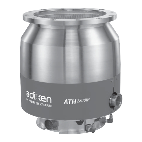
Summary of Contents for Pfeiffer Vacuum ATH 2800 MT
- Page 1 ATH 2800 M/MT - ATH 3200 M/MT Turbopumps Operating instructions Operating instructions...
- Page 2 ATH 2800 M/MT - ATH 3200 M/MT Turbopumps Welcome Dear Customer, You have just purchased an adixen Magnetically levitated turbopump. We would like to thank you and are proud to count you as one of our customers. This product has benefited from adixen Vacuum Products many years of experience in the field...
- Page 3 ATH 2800 M/MT - ATH 3200 M/MT Turbopumps This product complies with the requirements of European Directives, listed in the Declaration of Conformity contained in G 100 of the controller’s operating instructions. Copyright/Intellectual property: The use of adixen products are subject to copyright and intellectual property rights in force in any jurisdiction.
-
Page 4: General Contents
General contents : 113190 ANUAL REFERENCE : 04 - January 2013 DITION ATH 2800 M/MT - ATH 3200 M/MT operating instructions Translated from original version Chapter A INTRODUCTION A 150 - Introduction to the ATH 2800 M/MT- ATH 3200 M/MT pumps A 200 - Control loop of the pump A 210 - The pump operating principle A 400 - Technical characteristics of the pumps... - Page 5 General contents : 113190 ANUAL REFERENCE : 04 - January 2013 DITION ATH 2800 M/MT - ATH 3200 M/MT operating instructions Translated from original version Indicates an imminently hazardous situation that, if not avoided, will result in death or severe injury (extreme situations). Before switching on the product, study the Operating instructions and make sure you follow the safety instructions it gives.
- Page 6 Introduction ATH 2800 M/MT - ATH 3200 M/MT Operating instructions Detailed contents A 150 Introduction to the ATH 2800 M/MT, ATH 3200 M/MT pumps A 200 Control loop of the pump - 5 active axis - Unbalanced force rejection control A 210 The pump operating principle - Pumping principle...
- Page 7 A 150 Introduction to ATH 2800 M/MT - ATH 3200M/MT pumps A magnetically levitated turbopump Five active axes Rotor position control in 5 directions. Unbalanced Force Rejection Control Lowest possible levels of noise and vibration. Automatic adjustment to any imbalance of the rotor, from very low speed.
- Page 8 A 200 Control loop of the pump The mobile assembly formed by the turbo rotor and the shaft is 5 active axis known as the rotor. The rotor is driven by the motor and held in suspension by magnetic fields generated by electromagnets housed in an active bearing.
- Page 9 A 200 Control loop of the pump Unbalanced force The unbalanced force rejection control is an electronic function, that monitors the rotor position, allowing it to rotate rejection control in its own axis of inertia. Changes in the rotor balance, due to deposit built-up during the life time of the pump, are automatically compensated by the unbalanced force rejection control.
- Page 10 A 210 The pump operating principle Pumping principle The ATHM pump integrates the advantages of a multi-staged turbomolecular pump with a spiral helix molecular drag section. The turbomolecular section provides high pumping speeds and high ultimate vacuum. The molecular drag section provides a high compression ratio and extends forevacuum tolerance.
- Page 11 A 210 The pump operating principle The hybrid- At the pump exhaust, the gases are evacuated to atmosphere by a turbopump in an primary pump. The ATHM compression ratio is set by the design. The pumping installation performances depend of the primary pump and of the installation. INLET ATMOSPHERIC PRESSURE...
- Page 12 A 210 The pump operating principle The back-up ball They are dry-lubricated ceramic ball bearings. bearings They are never used in normal operation, since the rotor is not in contact with the ball bearings. The back-up ball bearings are only used to protect the pump in accidental air in-rushes, accidental shocks or power failure.
- Page 13 Technical characteristics of the pumps The performances of the pumps CHARACTERISTICS UNITS ATH 2800 M ATH 2800 MT ATH 3200 M ATH 3200 MT Flange (in) DN 250 ISO F / VG 250 DN 320 ISO F / VG 350...
- Page 14 Technical characteristics of the pumps performances of the pumps CHARACTERISTICS UNITS ATH 2800 M ATH 2800 MT ATH3200 M ATH3200 MT Run-up time up to 90% of nominal rotation < 10 speed, with exhaust pressure < 0.1 hPa ** Maximum baking temperature °C...
- Page 15 A 400 Technical characteristics of the pumps ATH 2800 M/MT Dimensions HEATED VERSION (MT model) M3 fixing hole to connect the pump to the earth Exhaust DN40 ISO-KF 203.5 /8.1 /6.61 /5.75 129.5 /7.17 Available to connect a functional earth Inlet flange A°...
- Page 16 A 400 Technical characteristics of the pumps ATH 3200 M/MT M3 fixing hole to connect Dimensions the pump to the earth HEATED VERSION (MT model) 203.5 /8.1 /5.16 /6.61 /5.75 /7.17 Available to connect a functional earth Inlet flange A° UNHEATED VERSION DN 320 ISO-F 20 235,7 319,1 293,8 340,4 325,7 351,4 332,7 425...
- Page 17 A 510 The accessories of the pump This screen protects the pump against solid particles. It is integrated into the pump housing. DN 250 (S. Steel) Bent screen + bored clip (mesh size 8 mm) 112128 DN 320 (S.Steel) Bent screen + bored clip (mesh size 8 mm) 112132 VG 350 (S.Steel) Bent screen + bored clip...
- Page 18 A 510 The accessories of the pump Purge valve (50 sccm) Purge valve (operate only by the 24 VDC 111921S customer tool) * The purge flow warranties a gas flushing for back-up ball bearing protection from the pumped process gases. The purge of this valve can be isolated during an air tightness test.
- Page 19 A 510 The accessories of the pump Thermostatic cable for (MT Models) Length A460082-010 3.5 m A460082-035 A460082-050 10 m A460082-100 20 m A460082-200 Water valve cable Length A462401-010 3.5 m A462401-035 A462401-050 10 m A462401-100 20 m A462401-200 An entire range of connection accessories is available in the catalog (clamping ring, centering ring, etc.).
-
Page 20: Accessory Dimensions
A 515 Accessory dimensions Plug coil Can rotate Purge valve (50 sccm) 22 (0.86) dimensions mm (inch) 83.3 (3.28) 30 (1.18) Pump connection Air inlet valve Connector for coil Pump connection (possible to rotate) dimensions mm (inch) 1/8NPT female connector (air inlet) DN 40 ISO KF 82 (3.23) - Page 21 A 515 Accessory dimensions Water valve (0.59) Cable water valve dimensions mm (inch) Inlet and outlet (0,59) 1/8 NPT female Scale 13/20 38,7 (1.52) 47,7 (1.88) adixen Vacuum Products - Operating instructions - ATH 2800 M/MT - ATH 3200 M/MT...
- Page 22 Start-up ATH 2800 M/MT - ATH 3200 M/MT Operating instructions Detailed contents B 100 Safety instructions for installation B 201 Unpacking and storage of the pump B 300 Pump connections to an installation - Equipment installation conditions - Pump connection instructions - Why securing pump installation ? - Worst Case Turbo Pump Crash Scenario Definitions B 310...
- Page 23 B 100 Safety instructions for pump and controller installation Indicates a potentially hazardous situation which, if not avoided, could result in property damage. Indicates a potentially hazardous situation which, if not avoided, could result in moderate or minor injury. It may also be used to alert against unsafe practices.
-
Page 24: Installation
B 100 Safety instructions for pump and controller installation The turbomolecular pumps can’t evacuate at atmospheric pressure, they are connected to a roughing pump. For a transient period, they can start to run at atmospheric pressure. Our products are designed to comply with current EEC regulations. Users making their own modifications to the product are liable to break its compliance with these regulations, degrade its EMC (electromagnetic compatibility) rating, and make it unsafe to use. - Page 25 B 100 Safety instructions for pump and controller installation Installation (cont’d) The user and /or OEM are ultimately responsible for operating the equipment in a safe manner. The manufacturer has no control over the types of gases exposed to this pump. This is the user and/or the OEM’s responsibility to follow the necessary safety requirements.
- Page 26 B 100 Safety instructions for pump and controller installation Installation (cont’d) Electric shock hazard. The voltages and currents in use can induce electric shock. Isolate and lock out power line to the product before maintaining it /or removing the cover. Only skilled, authorized people may carry out maintenance work.
- Page 27 B 100 Safety instructions for pump and controller installation Installation (cont’d) Safety interlock. The pump motor is protected against overload through the drive «start/ stop» and enable control circuitry of the variable speed controller. The drive start/stop includes solid state components. If hazards due to accidental contact with moving machinery or unintentional flow or liquid, gas or solids exist, an additional hardwired stop circuit is required to remove input power.
-
Page 28: Other Labels
B 100 Safety instructions for pump and controller installation Labels stuck on the product This label indicates that handling the pump can cause muscle strain or back injury. For all product handling, use the appropriate handling devices. This label indicates that some of the internal parts are energized and could cause electrical shocks in case of contact. -
Page 29: Pump Handling
B 201 Unpacking and storage of the pump Unpacking Make sure the equipment shows no sign of transport damage. If it has been damaged, take the necessary steps to record this with the carrier and inform the manufacturer. In all cases, we recommend keeping the packaging (reusable materials) for further transport of the equipment or for prolonged storage. - Page 30 B 201 Unpacking and storage of the pump The product is supplied with the inlet and exhaust blancked off. This prevents foreign bodies entering the pump during transport and storage. Do not remove these blanking plates until you are ready to install the product on the vacuum line.
-
Page 31: Pump Connections To An Installation
B 300 Pump connections to an installation Equipment installation conditions The equipment frame on which the pump is installed must be sufficiently rigid to absorb the kinetic energy of the rotor in case of pump rotor crash. For this, take into account : •... - Page 32 B 300 Pump connections to an installation Pump connection Magnetic Turbopumps are designed so as to prevent any safety hazard to the user in standard operating conditions. instructions However, some operating conditions may generate hazards Why securing for the user and the environment : the kinetic energy stored Pump installation? in a turbopump is very high.
- Page 33 B 300 Pump connections to an installation Worst Case Turbo The kinetic energy of the rotor has to be absorbed by the installation if the pump seizes suddenly. Pump Crash Scenario In the worst case the rotor splits into 2 parts at nominal speed. The Definitions impact of the rotor parts creates the following transient loads.
- Page 34 B 300 Pump connections to an installation Inlet flange installation The resulting maximum loads from a crash have to be taken into conditions (item 2) account by the pump assembly bolts. Design and secure the pump frame so that it can withstand the loads.
-
Page 35: Vacuum Connections
B 310 Inlet and exhaust connections Vacuum connections Do not expose any part of the human body to vacuum. The product is supplied with the inlet and exhaust sealed. Remove these blanking plates when you are ready to connect the product on your vacuum system. - Page 36 B 310 Inlet and exhaust connections At inlet: Check that an inlet screen accessory is installed on the pump ; if not, install it. (pumps are delivered with inlet screen filter). Screen filter Mounting of the insertable Position the screen (2) into the inlet housing groove (1), bend inlet screen side opposite to the rotor.
- Page 37 B 330 Nitrogen purge and air inlet valve device connections Characteristics of A filtered dry nitrogen supply with the following characteristics is required: filtered dry nitrogen O concentration : < 1 ppm supply concentration : 1 ppm - Dew point < 22 °C - Dust <...
-
Page 38: Air Inlet Valve
B 330 Nitrogen purge and air inlet valve device connections When the inert gas purge is stopped, the pumped gases can pass from rough vacuum side to high vacuum side and damage the pump bearings. It is advised to maintain the purge flow as long as the rotor is running to protect pump internal parts. -
Page 39: Water Line Connection
B 340 Water cooling connection Characteristics In order to avoid corrosion and clogging of the cooling pipes, it is recommended to use cooling water with the following of water cooling characteristics: treated soft water or non-corrosive industrial water pH between 7.5 and 11 - Hardness: <... - Page 40 B 340 Water cooling connection For ATH 2800-3200 - Provide a water inlet pipe and a tap to adjust M models the flow rate. - Connect the water inlet line to one of the cooler water fittings 1/4 NPT female on the pump, with the other fitting connected to the water Water OUT...
-
Page 41: Typical Connections
B 401 Typical electrical wiring diagram Typical connections In this installation, we use: - a roughing isolation valve V1 between the turbo pump and the roughing pump; - a high vacuum isolation valve V2 between the turbo pump and the chamber to be pumped; - a relay K1, their contacts drive the valve V1 and the roughing pump power supply;... -
Page 42: Operation
Operation ATH 2800 M/MT - ATH 3200 M/MT Operating instructions Detailed contents C 100 Safety instuctions for product use Refer to the Magpower operating instructions to have information about pump operation adixen Vacuum Products - Operating instructions - ATH 2800 M/MT - ATH 3200 M/MT... - Page 43 C 100 Safety instructions for product use Before using pump and controller, make sure that the mechanical and electrical connections have been made according to the safety recommendations: refer to chapter B from pump operating instructions and to associated controller operating instruction manual.
- Page 44 C 100 Safety instructions for product use Standard precautions before any maintenance operations: Before performing a maintenance operation, stop the pump. When the pump is at rest, switch off the pump by setting the controller main switch to «0», wait 5 minutes before disconnecting the main cable. If this last one remains connected, some components will still be energized.
-
Page 45: Maintenance
Maintenance ATH 2800 M/MT - ATH 3200 M/MT Operating instructions Detailed contents D 100 Safety instructions for product removal D150 Maintenance frequency adixen Vacuum Products - Operating instructions - ATH 2800 M/MT - ATH 3200 M/MT... - Page 46 D 100 Safety instructions for product removal Maintenance must be performed by a skilled maintenance operator trained in the relevant health and safety aspects (EMC, electrical hazards, chemical pollution, etc.). Isolate the product from all energy sources (mains electricity, compressed air, water, gas ...) before starting work.
- Page 47 D 100 Safety instructions for product removal Users are advised: Wear gloves, protective glasses, any appropriated safety equipment. Ventilate the premises well. Do not eliminate maintenance waste via standard disposal channels. Have it destroyed by a qualified company if necessary. Install the inlet and exhaust blanking plates, thus delivered with the pump or available as accessories ( E100) .
-
Page 48: Maintenance Frequency
D 150 Maintenance frequency Back-up ball bearings When the pump is running, the rotor is levitated magnetically. There is therefore no friction between moving and fixed parts. When the pump is stopped by the controller, the back-up ball bearings are not used. The rotor remains levitated by magnetic ball bearings. -
Page 49: Maintenance Instructions
Maintenance instructions ATH 2800 M/MT - ATH 3200 M/MT Operating instructions Detailed contents E 50 Replacement of the water valve coil - Coil dismantling - Coil reassembling E 100 Shipping procedure for contaminated pumps - Connecting ports - Rough decontamination procedure - General flushing - Purge / inlet flushing - Pressurize the pump... - Page 50 E 50 Replacement of the water valve coil Coil dismantling Unscrew the M5 fitting of the valve and remove it. Remove the spring clip. Remove the coil and replace it by a new one. Coil reassembling Put again the spring clip . Install the new o’ring on the M5 fitting.
-
Page 51: Shipping Procedure For Contaminated Pumps
E 100 Shipping procedure for contaminated pumps Study the safety instructions related to preventive maintenance D 100. The user must stick this label on the product to warn against WARNING pumped process gas that could be dangerous and toxic and could cause severe injuries or death. - Page 52 E 100 Shipping procedure for contaminated pumps Description D Purge port DN 16 1/8 BSPT flange with anti-suckback valve pressurisation A458805 including an injector Injector 106859 Note : Some pressurization kits including connecting Description accessories for inlet, Kit for DN 200-ISO-F flange + Purge DN 16 108499 exhaust and purge ports, Kit for DN 250-ISO-F flange + Purge 1/4 VCR...
- Page 53 E 100 Shipping procedure for contaminated pumps Pressurize the Blank the inlet port and exhaust port. pump Pressurize the pump with dry nitrogen* to an absolute pressure of 110 kPa using the injector. * Characteristics of dry nitrogen: B 330. adixen Vacuum Products - Operating instructions - ATH 2800 M/MT - ATH 3200 M/MT...
-
Page 54: Maintenance Components
Maintenance components ATH 2800 M/MT - ATH 3200 M/MT Operating instructions Detailed contents F 000 Spare parts - Instructions of use - Replacement of parts and use of non genuine parts F 100 First level maintenance parts adixen Vacuum Products - Operating instructions - ATH 2800 M/MT - ATH 3200 M/MT... - Page 55 F 000 Spare parts - Instructions of use Replacement of Our products are designed to comply with current EC regulations and guarantee optimal operating conditions with parts and use of non maximum safety conditions for the user. genuine parts Any modification of the product made by the user is liable to lead to non-compliance with the regulations, or even to put into doubt the performance of the product and the user’s safety.
- Page 56 F 100 First level maintenance parts For air inlet and purge valve Coil 24 V DC 038066 Dust filter Replace regularly the dust filter when used in dusty air Dust filter 106229 A complete range of connecting accessories is available in the manufacturer’s catalogue (flanges, fittings...).
- Page 57 Appendix ATH 2800 M/MT - ATH 3200 M/MT Operaring instructions Detailed contents G 150 Pumping curves G 200 Service adixen Vacuum Products - Operating instructions - ATH 2800 M/MT - ATH 3200 M/MT...
-
Page 58: Pumping Curves
G 150 Pumping curves Pumping speed (l/s) adixen Vacuum Products - Operating instructions - ATH 2800 M/MT - ATH 3200 M/MT... - Page 59 G 150 Pumping curves Pumping speed (l/s) adixen Vacuum Products - Operating instructions - ATH 2800 M/MT - ATH 3200 M/MT...
- Page 60 Fill out the «Service Request/Product return» form and send it to your Service Center local Pfeiffer Vacuum Service contact. Include the confirmation on the service request from Pfeiffer Vacuum with your shipment. Fill out the declaration of contamination and include it in the shipment (mandatory!).
- Page 61 Pfeiffer Vacuum stands for innovative and custom vacuum Pfeiffer Vacuum stands for innovative and custom vacuum Vacuum Solutions Vacuum Solutions from a single Source from a single Source solutions worldwide, technological perfection, competent advice solutions worldwide, technological perfection, competent advice and reliable service.
Need help?
Do you have a question about the ATH 2800 MT and is the answer not in the manual?
Questions and answers