
Related Manuals for Pfeiffer Vacuum A 100 L


Summary of Contents for Pfeiffer Vacuum A 100 L
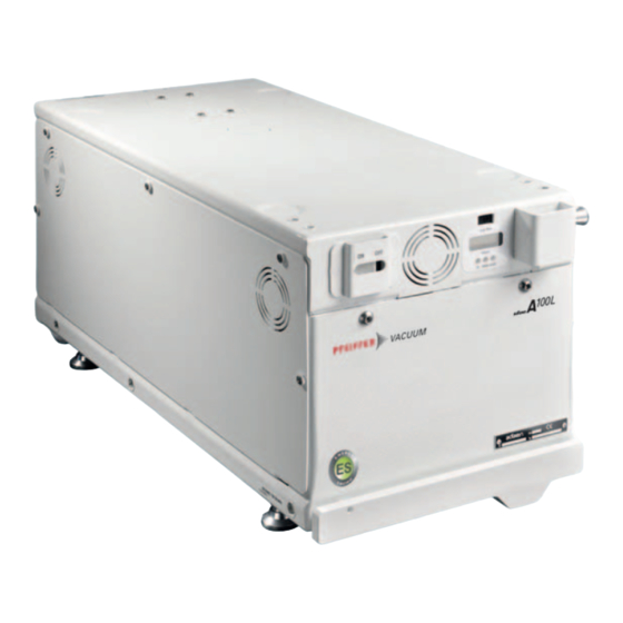
- Page 1 OPERATING INSTRUCTIONS Translation of the Original A 100 L - A 100 L ES Multi-stage Roots pump, compact, for light duty applications...
- Page 2 These operating instructions describe all models and variants of your product. Note that your product may not be equipped with all features described in this document. Pfeiffer Vacuum constantly adapts its products to the latest state of the art without prior notice. Please take into account that online operating instructions can deviate from the printed operating instructions supplied with your product.
-
Page 3: Table Of Contents
Electrical connection 5.5.1 Customer electrical installation protection measures 5.5.2 Mains connection Operation Preliminary precautions for use The control modes Specific features of the A 100 L ES model's operation Local mode operation Remote mode operation Operation monitoring Maintenance Maintenance safety instructions... - Page 4 Malfunctions Malfunction and fault indication The pump does not start The pump is running, an indicator light is on The pump stops running Service solutions by Pfeiffer Vacuum Accessories Technical data and dimensions 12.1 General 12.2 Technical characteristics 12.2.1Environmental conditions 12.2.2Cooling water characteristics...
- Page 5 List of tables List of tables Tbl. 1: Conversion table: Pressure units Tbl. 2: Conversion table: Units for gas throughput Tbl. 3: Environmental characteristics Tbl. 4: Cooling water characteristics Tbl. 5: Nitrogen characteristics Tbl. 6: Compressed dry air characteristics (CDA) Tbl.
- Page 6 List of figures List of figures Fig. 1: Safety label locations Fig. 2: Fitting the lifting strap Fig. 3: Installation of the removable handle Fig. 4: The Human/Machine Interface Fig. 5: Operating position Fig. 6: Stacking of two pumps Fig. 7: 16-pin remote control connector wiring Fig.
-
Page 7: About This Manual
Keep the manual for future consultation. 1.1 Validity These operating instructions are a customer document of Pfeiffer Vacuum. The operating instructions describe the functions of the named product and provide the most important information for the safe use of the device. The description is written in accordance with the valid directives. The information in these operating instructions refers to the product's current development status. -
Page 8: Pictographs
Loc/Rem Control mode switch (local or remote control) N2 IN Connecting the nitrogen or compressed dry air circuit (A 100 L ES) CPC Earth connection This label warns users about the risk of crushing or cutting due to moving parts: keep a safe distance and/or keep your hands away from the moving parts. -
Page 9: Abbreviations
About this manual This label indicates that the power supply must be switched off before con- necting and/or disconnecting the pump. The main power supply must be switched off before connecting and/or disconnecting the pump. This label indicates that the product has been certified in accordance with quality control when leaving the factory. -
Page 10: Safety
Safety 2 Safety 2.1 General safety information The following 4 risk levels and 1 information level are taken into account in this document. DANGER Immediately pending danger Indicates an immediately pending danger that will result in death or serious injury if not observed. ►... - Page 11 Safety WARNING Risk of electric shock due to non-compliant electrical installations This product uses mains voltage for its power supply. Non-compliant electrical installations or installa- tions not done to professional standards may endanger the user’s life. ► Only qualified technicians trained in the relevant electrical safety and EMC regulations are au- thorized to work on the electrical installation.
-
Page 12: Precautions
Safety WARNING Risk of burns in case of contact with hot surfaces Component temperature remains high, even after the pump has stopped. There is a risk of burns through contact with hot surfaces, especially at the pump exhaust. ► Wait for the product to fully cool down before working on it. ►... -
Page 13: Foreseeable Misuse
Safety 2.3 Foreseeable misuse Misuse of the product will render the warranty and any claims void. Any use, whether intended or not, that diverges from the uses already mentioned will be treated as non-compliant; this includes but is not limited to: ●... -
Page 14: Transportation And Storage
Transportation and Storage 3 Transportation and Storage 3.1 Receipt of the product Condition of the delivery ● Check that the product has not been damaged during transport. ● If the product is damaged, take the necessary measures with the carrier and notify the manufacturer. -
Page 15: Storage
► The pump inlet, exhaust and purge blanking plates must be kept in place until the pump is instal- led. ► Only remove the blanking plates when the pump is connected to the pumping line. Pfeiffer Vacuum recommends storing the products in their original transport packaging. 15/62... - Page 16 4. When nitrogen starts flowing from the exhaust, seal it with the accessories provided. 5. Disconnect the nitrogen supply from the connector. Never store a pump that has been used! Return it to the service center (see chapter “Service solu- tions by Pfeiffer Vacuum”, page 38). 16/62...
-
Page 17: Product Description
Product description 4 Product description 4.1 Product identification To correctly identify the product when communicating with our service center, always have the informa- tion from the product rating plate available (see chapter "Labels"). 4.1.1 Scope of delivery ● 1 vacuum pump ● 2 water connectors ●... -
Page 18: Installation
Installation 5 Installation 5.1 Pump set-up Exh. Exh. Fig. 5: Operating position Holes for attaching the pump to a frame Exh. Pump Exhaust IN Inlet The product must be used in horizontal position, standing on its feet. 1. Déterminer l'emplacement de la pompe. 2. -
Page 19: Installing The Pump In A Seismic Environment
Installation Fig. 6: Stacking of two pumps 1 Locking foot (pump A) Locking foot (pump B) 2 Upper bracket (pump B) Upper pump 3 Screw Lower pump 4 Lower bracket (pump A) Procedure for stacking two pumps The product is fitted with brackets to facilitate the stacking of two pumps. 1. -
Page 20: Connecting The Water Circuit
Installation 1 Location of fixing screws (supplied) Location of the fixing accessories (supplied by the custom- Installing the brackets Move the pump into its operating position. 1. Install the 4 brackets opposite the holes provided for this purpose, identified by a "Seismic tie down"... -
Page 21: Connecting The Nitrogen Circuit
Installation WATER IN WATER OUT Connecting the water circuit Water connectors specified on the order will be packaged separately. 1. Connect the water pipes to the connectors: – Water inlet = female connector – Water outlet = male connector 2. Connect the pipework to the pump’s WATER IN and WATER OUT connectors. 3. -
Page 22: Connecting To The Pumping Line
Installation The nitrogen connector, separetly conditionned, is designed to be connected on 6mm pipe exterior di- ameter/ 4 mm interior (provided by the customer). 1. Connect the nitrogen pipe to the supplied connector. 2. Then connect to the N2 IN of the pump. 5.1.5 Connecting to the pumping line The user and/or product OEM is ultimately responsible for the equipment and must apply the specific safety instructions, in accordance with local legislation. -
Page 23: Remote Control Via The 16-Pin Connector
Installation 5.3 Remote control via the 16-pin connector NOTICE Safety of Extra-Low Voltage circuits The remote control circuits are equipped with dry contact outputs (50 V - 1 A max). Overvoltages and overcurrents can result in internal electrical damage. Users must observe the following wiring condi- tions: ►... -
Page 24: Remote Control Via The 19-Pin Connector
Installation Pump status 9-10 11-12 13-14 Pump in operation + warning closed open closed closed closed Pump stopped + alarm open closed open closed open 5.4 Remote control via the 19-pin connector NOTICE Safety of Extra-Low Voltage circuits The remote control circuits are equipped with dry contact outputs (50 V - 1 A max). Overvoltages and overcurrents can result in internal electrical damage. -
Page 25: Electrical Connection
Installation Contact Function Authorization to control an isolation valve on the equipment Pump failure Pump status Pump in operation closed closed closed closed closed closed closed Pump stopped open closed closed closed closed open closed Pump in operation + warning closed open open... -
Page 26: Mains Connection
Installation Differential circuit breaker To protect individuals against insulation faults, you must install a differential circuit breaker (see chapter "Electrical characteristics"). If necessary, contact our service center. The applicable local regulations must be complied with at all times. Earthing Users must provide a second circuit protective conductor (earth) whose cross-section is at least equal to that of the conductors. - Page 27 Installation 1. Lock the female connector to the power socket with the lock. Absence of emergency stop The vacuum pump is not equipped with an emergency stop device (EMS) or a lock-out de- vice. The vacuum pump is designed to be integrated into equipment fitted with an emer- gency stop device.
-
Page 28: Operation
Operation 6 Operation 6.1 Preliminary precautions for use WARNING Risk of poisoning when process gases are present in the atmosphere The manufacturer has no control over the types of gases used with the pump. Process gases are of- ten toxic, flammable, corrosive, explosive and/or otherwise reactive. There is a risk of serious or fatal injury if these gases are allowed to escape freely into the atmosphere. -
Page 29: Specific Features Of The A 100 L Es Model's Operation
6.3 Specific features of the A 100 L ES model's operation By design, the pump A 100 L ES is characterized by its reduced energy consumption thanks to the ‘En- ergy Saving‘ option: The option incorporates a system that reduces the power consumed when operating at ultimate pres- sure. -
Page 30: Operation Monitoring
Operation Rotational speed setting 1. Apply 0 to 10V direct voltage to analog input A2 of the remote control connector to adjust the rota- tion speed of the pump: ● the speed decreases from the maximum value (0 V) to the minimum value (10 V). Speed Maxi Mini... - Page 31 Operation Message Indicator light status Operating status Warning Green and yellow indicator lights First level temperature warning on the pump: pump contin- ues to run at maximum speed. ● Rectify the problem to eliminate the fault . Motor temp Red indicator light on Motor temperature alarm: the pump is stopped.
-
Page 32: Maintenance
Maintenance 7 Maintenance 7.1 Maintenance safety instructions Safety instructions regarding corrosive gases do not apply to pumps intended for load-lock or transfer chamber pumping. In the event of the accidental presence of corrosive gases, users must observe the following precautions when disconnecting the pump from the installation and working on the product. DANGER Risk to health posed by residual traces of process gases inside the pump Process gases are toxic and hazardous to health. -
Page 33: Maintenance Frequency
Any other maintenance operation must be carried out by our service center (see chapter “Service solutions by Pfeiffer Vacuum”, page 38). ► Clean the outer surfaces of the product using a clean, lint-free cloth and a product that will not damage the screen-printed surfaces or adhesive labels. -
Page 34: Draining The Water Circuit
Maintenance Disconnection procedure 1. Switch off the pump by setting the circuit breaker to OFF. 2. Switch off the circuit breaker of the customer installation. 3. Disconnect the power cable at the electrical connector. 4. Disconnect all connectors at the rear of the pump. 5. -
Page 35: Decommissioning
The manufacturer shall only be required to take back equipment that is complete and unmodified, using Pfeiffer Vacuum SAS original spare parts, sold by Pfeiffer Vacuum and including all assemblies and sub-assemblies. This obligation does not cover the shipping cost to a reclamation facility or services provided, for which the customer will be invoiced. -
Page 36: Malfunctions
Malfunctions 9 Malfunctions 9.1 Malfunction and fault indication When problems occur, users are informed by: ● The relevant indicator light coming on: yellow for warnings, red for alarms. ● Fault contacts on the remote connector are being activated. ● Pumping shutdown although the OFF command has not been activated. ●... -
Page 37: The Pump Stops Running
Malfunctions Symptom Cause Remedy The temperature of the functional Water problem Check the water circuit supply. block is too high Check that the water pipes are not obstructed or check for leaks. Check that the water flow is at least 100 l/h. Check the pumping conditions. -
Page 38: Service Solutions By Pfeiffer Vacuum
We are always focused on perfecting our core competence – servicing of vacuum components. Once you have purchased a product from Pfeiffer Vacuum, our service is far from over. This is often exactly where service begins. Obviously, in proven Pfeiffer Vacuum quality. - Page 39 Service solutions by Pfeiffer Vacuum 5. Prepare the product for transport in accordance with the provisions in the contamination declaration. a) Neutralize the product with nitrogen or dry air. b) Seal all openings with blind flanges, so that they are airtight.
-
Page 40: Accessories
Accessories 11 Accessories Accessory Description Dimension Seismic brackets Set of 4 brackets 109790 Female 1/4" NPT connector Water inlet 076721 1/4" NPT male connector Water outlet 076720 Nitrogen pressurization kit including 107956S Exhaust blank-off flange DN 25 ISO-KF Quick-connect clamp DN 25 ISO-KF Centering ring fitted with o-ring DN 25 ISO-KF Inlet blanking plate + 1/8’’... -
Page 41: Technical Data And Dimensions
Technical data and dimensions 12 Technical data and dimensions 12.1 General Basic principles for the Technical Data of Pfeiffer Vacuum compact multi-stage Roots pumps for light- duty applications: ● Recommendations of PNEUROP committee PN5 ● ISO 21360; 2007: “Vacuum technology - Standard methods for measuring vacuum-pump perform- ance - General description”... -
Page 42: 1Environmental Conditions
Technical data and dimensions mbar Torr | mm Hg mbar 0.75 1 · 10 1000 1000 1 · 10 0.01 0.01 1 · 10 1 · 10 7.5 · 10 0.75 1 · 10 0.01 1000 Torr | mm Hg 1.33 1.33 ·... -
Page 43: 2Cooling Water Characteristics
Technical data and dimensions 12.2.2 Cooling water characteristics 5.5 to 9 Chloride (ppm) Chlorides 100 to 20 ppm depending on the Hardness < 10 °fH (French degree) < 2 milliequivalent/L < 100 mg/L of CaCO (calcium carbonate) Total dissolved solids < 300 mg/L LSI (Langelier satura- - 0.5 <... -
Page 44: 5Electrical Characteristics
Technical data and dimensions Inlet 1/8" NPT male connector Stainless steel Inlet Male connector for 1/4" tube Stainless steel 12.2.5 Electrical characteristics Main switch short circuit cut-off capacity 10 kA GFI (or RCD) type B, differential circuit breaker compatible with TT electrical networks 300 mA for TN and IT networks, use appropriate protection measures Tbl. -
Page 45: Tbl. 9: Load Distribution By Foot: Case Of A Single Pump
Technical data and dimensions Center of gravity (mm) Load by foot 22 N 24 N 29 N 28 N According to standard Semi S2-200 Section 19 Tbl. 9: Load distribution by foot: case of a single pump Dimensions of stacked pumps Exh. -
Page 46: Tbl. 10: Load Distribution By Foot: 2 Pump Stacked
Technical data and dimensions Center of gravity (mm) Load by foot 44 N 48 N 58 N 56 N According to standard Semi S2-200 Section 19 Tbl. 10: Load distribution by foot: 2 pump stacked 46/62... - Page 47 Technical data and dimensions Fig. 11: Dimensions of the pump equipped with seismic brackets Load distribution on seismic brackets Case of a single pump 69 N -129 -272 N -183 -237 -258 -580 N -454 According to standard Semi S2-200 Section 19 47/62...
-
Page 48: Tbl. 11: Load Distribution On Seismic Brackets
Technical data and dimensions Load distribution on seismic brackets Case of 2 stacked pumps 334 N -300 -368 -356 N -642 -391 -511 -1845 N 1008 -1381 According to standard Semi S2-200 Section 19 Tbl. 11: Load distribution on seismic brackets 48/62... -
Page 49: Appendix
Appendix 13 Appendix 13.1 Installation of serial link RS-232/RS-485 NOTICE Risk of electromagnetic disturbance Voltages and currents can induce a multitude of electromagnetic fields and interference signals. In- stallations that do not comply with the EMC regulations can interfere with other equipment and the environment in general. - Page 50 Appendix Initial setting link configuration Description Value Serial link RS-232 Transmission speed 9600 bauds Data word length 8 bits Parity none (no parity) Stop bit Echo RS-232/RS-485 - 9-pin, male connector Assignment Data reception (RS-232) Data transmission (RS-232) RS-485: V- RS-485: V+ The user must use shielded links and connections in compliance with EMC and electrical safety stand- ards.
-
Page 51: Configuration Of Communication Protocol Rs-232
Appendix V(+) RS-485 communication V(-) 13.3 Configuration of communication protocol RS-232 When the wiring is carried out, to allow pump control and monitoring: 1. Set the circuit breaker to ON: the green LED located on the RS-232/RS-485 board is lit. 2. Send a command via the serial link: this command does not have priority over the operation in remote control mode via the SPI connector. - Page 52 SEL: Status of configuration parameters Example: #adr,A,B,C,D,E,F,G,H,I,J,K,L,M,N,O,P,Q,R,S,T<CR> Parameters 0 = Header character 1-3 = Address 4 = Separator character 5-11 = Reserved 12 = Separator character 13 = System selected (5 = A 100 L/A 200 L/A 180 L) 52/62...
- Page 53 44 = End-of-message character SET: Setting pump operating parameters Example: # adrSETXXYZZZZ<CR> Parameters Setting limit XX= 07 Revision interval: A 100 L/A 200 L/A 180 L. 0 = time x100 0010-0420 ZZZZ = value Example: 0010 corresponds with 1000 hours SYS: Pump Start/Stop...
-
Page 54: Configuration Of Communication Protocol Rs-485
1-3 = Address 4 = Separator character 5-9 = Operating time 10 = Separator character 11-15 = Maintenance time reached (A 100 L/A 200 L/A 180 L) 16-45 = Separator character 46 = End-of-message character 13.5 Configuration of communication protocol RS-485 The commands are identical to those of the RS-232 serial link: command list (see chapter “Command... -
Page 55: Command List Of Communication Protocol Rs-485
Appendix Parameter The number of characters depends on the command End character This is the message end character. The setting is ASCII 13 code <CR> The <LF> character is not taken into account. Example: Header character Pump address Order Order Parameter End character XXXX... - Page 56 Appendix Description Functions D: status of bit 4 parame- ters served served served served served served served served E: status of bit 5 parame- Select ters served served served System served served served bit 3,2,1,0 = 5 = ADP 100LON F: status of bit 6 parame- ters...
- Page 57 Appendix Order Description Functions c: warning bit 2 Reserved Reserved Reserved Reserved Reserved Reserved Reserved d: alarm bit Reserved Reserved Reserved Reserved Reserved Reserved Variator Alarm e: warning bit 3 Reserved Reserved Motor tem- Reserved Reserved Reserved Mainte- perature nance Warning Warning f: alarm bit 3...
-
Page 60: Declaration Of Conformity
EN 61000-6-2 : 2005 EN 61000-6-4 : 2007 The manufacturer's authorized representative in the United Kingdom and the authorized agent for compiling the technical documentation is Pfeiffer Vacuum Ltd, 16 Plover Close, In- terchange Park, MK169PS Newport Pagnell. Signature: Pfeiffer Vacuum SAS... -
Page 61: Declaration Of Incorporation Of Partly Completed Machinery
Declaration for product(s) of the type: Multi-stage Roots pump, compact A 100 L A 100 L ES We hereby declare that the listed product satisfies all relevant provisions of the following European Directives. Machinery 2006/42/EC (Annex II, no. 1 A)
Need help?
Do you have a question about the A 100 L and is the answer not in the manual?
Questions and answers