
Related Manuals for Pfeiffer Vacuum ACP 15


Summary of Contents for Pfeiffer Vacuum ACP 15
-
Page 1: Operating Instructions
OPERATING INSTRUCTIONS Translation of the original instructions ACP 15 Dry compact Multi-stage Roots pump... -
Page 2: Table Of Contents
Table of contents Table of contents About this manual ..........4 1.1 Validity. - Page 3 Table of contents 7.4.1 Disconnecting the pump from the installation ....33 7.4.2 Conditioning the pump for shipping......33 Decommissioning .
-
Page 4: About This Manual
About this manual Validity This operating manual is for customers of Pfeiffer Vacuum. It describes the functioning of the designated product and provides the most important information for safe use of the unit. The description follows applicable EU guidelines. All information provided in this operating manual refers to the current state of the product's development. -
Page 5: Pictographs
About this manual 1.2.2 Pictographs Prohibition of an action or activity in connection with a source of danger, the disregarding of which may result in serious accidents Warning of a displayed source of danger in connection with operation of the unit or equipment Command to perform an action or task associated with a source of dan- ger, the disregarding of which may result in serious accidents Important information about the product or this document... - Page 6 About this manual This label indicates that the power supply must be switched off before connecting and/ or disconnecting the pump. Any person responsible for installation or operation of the product must first refer to the operating manual. This label warns the user against potential risks associated with the use of this product. CAUTION ATTENTION Any person responsible for installation or operation of the product must first refer to the...
-
Page 7: Safety
Safety Safety Safety precautions Obligation to inform Any person responsible for installing, using or maintaining the product must first read the security instructions in this operating manual and comply with them. It is the operating customer’s responsibility to protect all operators against the dan- gers associated with the product, with the media pumped and with the entire instal- lation. -
Page 8: Protective Equipment
Safety WARNING Risk associated with process gases The user and/or integrator of the product is/are fully responsible for the operational safe- ty conditions of the equipment. The manufacturer has no control over the types of gases this pump is exposed to. Frequently process gases are toxic, flammable, corrosive, ex- plosive and/or otherwise reactive. -
Page 9: Proper Use
Safety WARNING Risk of injury due to falling objects When transporting parts/items by hand, there is a danger of loads slipping and falling down. Carry small and medium-size parts/items with two hands. Carry parts/items > 20 kg with a suitable lifting device. ... -
Page 10: Transport And Storage
Transport and storage Transport and storage Upon delivery, check that the product has not been damaged during transport. If the product is damaged, contact the carrier and notify the manufacturer. In all situations we recommend: Keeping the product in its original packaging so it stays as clean as it was when dis- patched by us. -
Page 11: Storage
Transport and storage Storage If the new pump is going to be put into storage: Storage of a new pump Keep the pump wrapped in its protective film. It is absolutely necessary to leave the inlet, the exhaust and purge blanking plates in place. -
Page 12: Product Description
The G version pump is compatible with traces of corrosive gases. Three purge gas jets G version protect low and high pressure bearings and dilute trace amounts of corrosive gases. Please contact Pfeiffer Vacuum to obtain more detailed information according to the ap- plications. -
Page 13: Man/Machine Interfaces
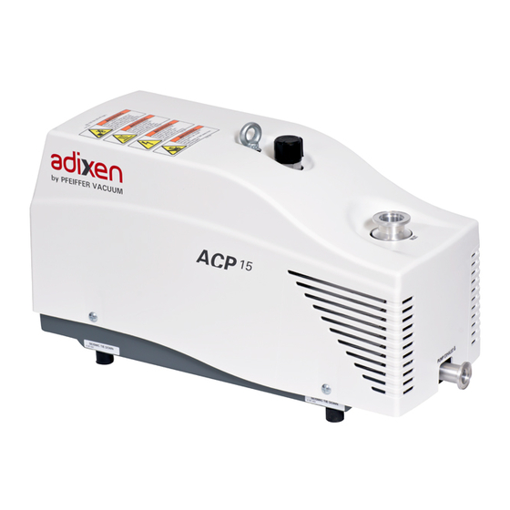
Product description Man/machine interfaces Fig. 2: ACP 15 with single-phase frequency converter Pump inlet Gas ballast (SD version) Pump exhaust Hoisting ring I/O mains switch Remote connector and RS-485 connector Power supply Hour meter Inert gas purge connection (G version) -
Page 14: Installation
Installation Installation Set-up The pump must be operated in the horizontal position in support on its feet, with the pumping axis vertical and the inlet opening upwards. Determine where the pump will be placed. Use the handling devices to position the pump in the desired location, lift the pump using hoisting rings (see 3.1). -
Page 15: Connection At Pump Inlet
Installation The O-rings located under the blanking plates are compatible with standard applications. Other types of connection accessories are available in the product catalogue. The inlet and exhaust connections must not cause stress that could lead to leaks in the pumping line. -
Page 16: Leak Test
Installation DANGER Risk of explosion If pyrophoric materials above the LEL (lower explosive limit) are sent to the pump, the nitrogen supply must make it possible to dilute this concentration. Ensure there is a sufficient flow of nitrogen to lower the concentration below the LEL. ... -
Page 17: Customer Electrical Installation Protection
Installation WARNING Risk of electromagnetic disturbance The product’s EMC behavior is guaranteed only if the relevant EMC standards are fol- lowed during installation. Use shielded cables and connections for the interfaces in interference-prone environ- ments. WARNING Hazard associated with non-compliant electrical installation Safe operation after installation is the operator’s responsibility. -
Page 18: Remote Connector Wiring
Installation NOTICE Operation in local mode There is no device to warn that the pump is operating in local mode. Provide a device to warn about local mode operation when the pump is not integrat- ed with equipment/host tool. 5.4.2 Connection to the mains power supply ... -
Page 19: Setting Of The Rotation Speed
Installation 5.5.2 Setting of the rotation speed ACP 15 model Contact Contact Contact Rotation speed S3 = 1 S4 = 0 S5 = 1 3600 S3 = 1 S4 = 0 S5 = 0 4200 S3 = 0 S4 = 1... -
Page 20: Rs-485 Serial Link Wiring
Installation RS-485 serial link wiring WARNING Risk of electromagnetic disturbance The product’s EMC behavior is guaranteed only if the relevant EMC standards are fol- lowed during installation. Use shielded cables and connections for the interfaces in interference-prone environ- ments. WARNING Electric shock hazard in case of contact When the product's mains switch is set at O, some internal components still have an... -
Page 21: Setting
Installation RS-485 communication 5.6.2 Setting When the wiring is done, to allow pump control via serial link, proceed as follows: Position the mains switch to I position. Send an order via the serial link: this order has no priority on remote control mode via dry contacts (see 5.5.1). -
Page 22: Command List
Set point speed can be set in steps of 10 min : minimum speed : 35 Hz ACP 15, maximum speed : 100 Hz Before changing the set point speed with RPM order, it is mandatory to send the SBY order. -
Page 23: Operation
Operation Operation Prerequisites to use WARNING Risk associated with process gases The user and/or integrator of the product is/are fully responsible for the operational safe- ty conditions of the equipment. The manufacturer has no control over the types of gases this pump is exposed to. - Page 24 Operation NOTICE Thermal safety The pump is fitted with temperature sensors which prevent operation or start-up when the temperature of the pump body is < 12 °C or > 40 °C. In order for the pump to operate: Operate the pump within the required temperature range (see 12.3.1). ...
-
Page 25: Matrix Gas/Applications
Operation Matrix gas/applications You are advised to use the appropriate pump version according to the applications and the nature of the gases pumped and apply the usual precautions to guarantee the reli- ability and safety of the procedure. Ensure that the gases pumped are compatible with the various materials (see 8.3). Minimum config- uration ACPG... -
Page 26: Different Control Modes
Operation Different control modes 3 control modes are available: The pump is controlled with I/O mains switch. The pump is running as a stand-alone part LOCAL of the equipment on which it has been integrated. The pump is remote controlled. The pump rotational speed is set by the opening and REMOTE closing dry contacts on the remote control connector (see 6.3.2). -
Page 27: Remote Mode Operation
Operation 6.3.2 Remote mode operation Wire and connect the remote connector located at the rear of the pump (see 5.5). Pump start-up Position the mains switch to I position: the pump is powered. Send a ’Start’ pump order via S1 contact : –... -
Page 28: Rs-485 Serial Link Operation
Operation 6.3.3 RS-485 serial link operation Wire and connect the serial link pins from the remote connector (see 5.6.1) Pump start-up Position the mains switch to I position: the pump is powered. Send an ’ACPON’ order via the serial link (see 5.6.3) : –... -
Page 29: Gas Ballast Operation
Operation 6.3.4 Operation monitoring The pump equipped with a three-phase frequency converter has two LED at the rear that indicate the pump operating status. LED status Display Description Green No power supply On, constant light The pump is powered. The pump has reached the selected speed. No default On, constant light ●... -
Page 30: Purge Operation
Operation Purge operation A gas purge circuit protects the low and high pressure bearings and dilutes trace Principle amounts of corrosive gases. When the inert gas pipe is connected on purge connection (see 5.2.3): Commissioning Inject inert gas purge according to the flow rate values (see 12.2). To ensure the proper discharge by the exhaust of corrosive gases, avoid to connect an Recommendations ES25S type silencer. -
Page 31: Maintenance
NOTICE Exclusion of liability Pfeiffer Vacuum accepts no responsibility concerning equipment damage, disrupted service or physical injury resulting from maintenance carried out by technicians who have not been trained in safety rules (EMC, electrical hazards, chemical pollution). Lia- bility and warranty claims shall be inadmissible in this case. -
Page 32: Maintenance Frequency
Maintenance frequency Description Frequency ACP 15 ACP 15 G Pump overhaul by Pfeiffer Vacuum ser- 20,000 h or 4 years vice center. Maintenance frequencies are typical values for non corrosive applications. For applica- tions using G version pump, these values can be reduced. -
Page 33: Standard Repair Exchange
Maintenance Standard repair exchange To proceed with a standard exchange, key steps must be followed in sequential order: – Disconnecting the pump from the installation (see 7.4.1) – Conditioning the pump for shipping (see 7.4.2) – Declaration of contamination (see 10) –... -
Page 34: Decommissioning
Vacuum, containing e.g. all its components and subassem- blies. This obligation will not cover the shipping cost to a Pfeiffer Vacuum reclamation facility. Before returning the product, please consult the Service procedure (see 10). Fill in the declaration of contamination form available on our website. -
Page 35: Malfunctions
Malfunctions Malfunctions Read the safety instructions for maintenance (see 7.1). Trouble at pump start-up Symptom Cause Remedy The pump does not start and the Mains switch Check the mains switch position to I. fan does not run The pump supply voltage is not compatible with ... -
Page 36: Service
Fill out the "Service Request/Product Return" form and send it to your local Pfeiffer Vacuum Service contact. Include the confirmation on the service request from Pfeiffer Vacuum with your ship- ment. Fill out the declaration of contamination and include it in the shipment (mandatory!). -
Page 37: Accessories
Accessories 11 Accessories Accessory Description Dimension Model Inlet filter Installed on the pump inlet, it allows to collect particles DN 25 ISO-KF IPF 25 111649 with a diameter greater than 25 microns (in clean ap- plications such as vacuum packing, metallurgy, lamp manufacture, evaporation, etc...). -
Page 38: Technical Data And Dimensions
Technical data and dimensions 12 Technical data and dimensions 12.1 General Basic principles for the Technical Data of Pfeiffer Vacuum Turbopumps: ● Recommendations of PNEUROP committee PN5 ● ISO 21360; 2007: "Vacuum technology - Standard methods for measuring vacuum- pump performance - General description"... -
Page 39: Facilities Characteristics
Technical data and dimensions Conversion table: gas throughput units mbar·l/s Pa·m sccm Torr·l/s atm·cm mbar·l/s 59.2 0.75 0.987 Pa·m 9.87 sccm 1.69 · 10 1.69 · 10 1.27 · 10 1.67 · 10 Torr·l/s 1.33 0.133 78.9 1.32 atm·cm 1.01 0.101 59.8 0.76... -
Page 40: Dimensions
Technical data and dimensions 12.4 Dimensions Fig. 7: ACP 15 /ACP 15 G - Dimensions (mm) Purge port (ACP 15 G model) Hoisting ring (with single-phase frequency converter) Hoisting rings (with three phase frequency converter) ACP 15/ACP 15 G M N Q R S... -
Page 41: Weight Distribution And Seismic Brackets
Pump frame 8 M 6 X 20 screw ,qty 4, grade 12-9 Fastening plate, thickness: 6 mm (delivered in the fastening kit) Model Load per foot (N) ACP 15 /ACP 15 G Tension (Fa) Single-phase/Three-phase Shearing (Fr) -
Page 42: Etl Mark
ETL Mark... -
Page 43: Declaration Of Conformity
● Restriction of the use of certain Hazardous Substances 2011/65/EU ● Low Voltage 2014/35/EU The technical file is drawn up by Mr Gilles Baret, Pfeiffer Vacuum SAS, [simplified joint stock company], 98, avenue de Brogny · B.P. 2069, 74009 Annecy cedex. - Page 44 VACUUM SOLUTIONS FROM A SINGLE SOURCE Pfeiffer Vacuum stands for innovative and custom vacuum solutions worldwide, technological perfection, competent advice and reliable service. COMPLETE RANGE OF PRODUCTS From a single component to complex systems: We are the only supplier of vacuum technology that provides a complete product portfolio.
Need help?
Do you have a question about the ACP 15 and is the answer not in the manual?
Questions and answers