
Related Manuals for Pfeiffer Vacuum adixen ATH 500 M


Summary of Contents for Pfeiffer Vacuum adixen ATH 500 M
- Page 1 ATH 500 M/MT Magnetically levitated turbopumps Operating instructions Operating instructions...
- Page 2 ATH 500 M-MT Magnetically levitated turbo pumps Welcome Dear Customer, You have just purchased an adixen magnetically levitated turbo pump. We would like to thank you and are proud to count you as one of our customers. This product has benefited from adixen Vacuum Products many years of experience in the field...
- Page 3 ATH 500 M-MT Magnetically levitated turbo pumps This product complies with the requirements of European Directives, listed in the Declaration of Conformity contained in G 100 of this Manual. Copyright/Intellectual property: The use of adixen products are subject to copyright and intellectual property rights in force in any jurisdiction.
-
Page 4: General Contents
General contents Manual reference: 114436 Edition: 04 - June 2012 ATH 500 M-MT Operating instructions Translated from original version Chapter A INTRODUCTION A 150 - Introduction to the ATH 500 M-MT A 200 - Control loop of the pump A 210 - The pump operating principle A 400 - The technical characteristics A 510 - The accessories of the pump Chapter B... - Page 5 General contents Manual reference: 114436 Edition: 04 - June 2012 ATH 500 M-MT Operating instructions Translated from original version Indicates a potentially hazardous situation which, if not avoided, could result in property damage. Indicates a potentially hazardous situation which, if not avoided, could result in moderate or minor injury.
- Page 6 General contents Manual reference: 114436 Edition: 04 - June 2012 ATH 500 M-MT Operating instructions Translated from original version Symbols, labels Description Warning : hot surface Warning : hazardous voltage Caution : risk of danger. Refer to the operating instructions before use Operating status 48 V 12 A...
- Page 7 Introduction ATH 500 M-MT User’s Manual Detailed contents A 150 Introduction to the ATH 500 M-MT A 200 Control loop of the pump - 5 active axis - Unbalanced force rejection control A 210 The pump operating principle - Pumping principle - The hybrid-turbo pump in an installation - The back-up bearings - Variation of the pump rotational speed...
- Page 8 A 150 Introduction to the ATH 500 M-MT A magnetically levitated hybrid turbo pump ATH 500 M with Five active axes Rotor position control in 5 directions. integrated electronic Unbalanced force rejection control Lowest possible levels of noise and vibration. Compensation for any unbalance of the rotor.
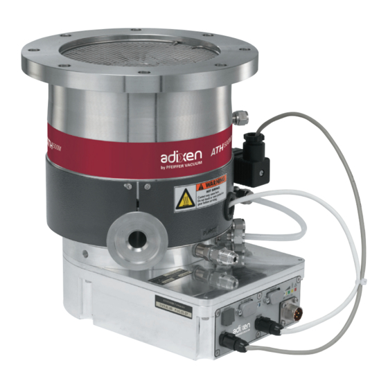
- Page 9 A 150 Introduction to the ATH 500 M-MT ATH 500 M Model For OEM version, see its own specific technical sheet. Integrated electronic 1 Exhaust port DN25 ISO KF 1/8 ‘‘BSPP female equipped with a filter 2 Integrated purge (50 sccm) B 330 3 Water fittings 1/8 NPT female...
- Page 10 A 150 Introduction to the ATH 500 M-MT ATH 500 MT Model Water in Water out 1 Exhaust port DN40 ISO KF 2 Integrated purge (50 sccm) 1/4 VCR B 330 3 Water fittings 1/4 double ring B 340 4 Service Idem ATH 500 M 5 RS232 or RS485 serial links Idem ATH 500 M 6 Remote connector...
-
Page 11: Air Cooled
A 150 Introduction to the ATH 500 M-MT Air cooled ATH 500 M Model The fan must be supplied by an external power supply 48 VDC, either ordered as an accessory ( A510), or provided by the customer. adixen Vacuum Products - Operating instructions - ATH 500 M-MT adixen Vacuum Products - Operating instructions - ATH 500 M-MT... - Page 12 A 200 Control loop of the pump 5 active axis The mobile assembly formed by the turbo rotor and the shaft is known as the rotor. The rotor is driven by the motor and held in suspension by magnetic fields generated by electromagnets housed in an active bearing.
- Page 13 A 200 Control loop of the pump Unbalanced force The unbalanced force rejection control is an electronic function, that monitors the rotor position, allowing it to rotate rejection control in its own axis of inertia. Changes in the rotor balance, due to deposit built-up during the life time of the pump, are automatically compensated by the unbalanced force rejection control.
- Page 14 A 210 The pump operating principle Pumping principle The ATH 500 M pump integrates the advantages of a multi-staged turbomolecular pump with a spiral helix molecular drag section. The turbomolecular section provides high pumping speeds and high ultimate vacuum. The molecular drag section provides a high compression ratio and extends the forevacuum tolerance up to the range of mbar.
- Page 15 A 210 The pump operating principle The hybrid- At the pump exhaust, the gases are evacuated to atmosphere by a primary pump. turbo pump in an The ATHM compression ratio is set by the design. The pumping installation performances depend on the primary pump and on the installation. INLET ATMOSPHERIC PRESSURE...
- Page 16 A 210 The pump operating principle The back-up ball They are dry-lubricated ball bearings. They are never used in normal operation, since the rotor is not in bearings contact with the ball bearings. The back-up bearings are only used to protect the pump in accidental air in-rushes, accidental shocks or power failure.
- Page 17 A 400 Technical characteristics of the pumps The performances of the pumps Characteristics UNITS ATH 500 M ATH500MT Flange (in) DN 100 ISO-F DN 160 ISO-F DN 160 ISO-F Flange (out) DN 25 ISO-KF DN 40 ISO-KF N2 purge flange 1/8 BSPP (ISO 228) 1/4VCR Rotation speed...
- Page 18 A 400 Technical characteristics of the pumps The performances of the pumps Characteristics UNITS ATH 500 M ATH500MT Run-up TIME < 2.0 Power consumption max. starting up power watt Nominal power watt Standby power watt < 50 Controller power supply 48 VDC Maximum leakage current not applicable ;...
- Page 19 A 400 Technical characteristics of the pumps Dimensions mm (inch) ATH 500M (8.94) RJ 45 / Service and HHR N = Nr equidistant holes (5.94) 62 MAXI M4 holes (2.44) SUB D 9 / RS 232 - 485 to connect the pump LED / Power supply EXHAUST...
- Page 20 A 400 Technical characteristics of the pumps Dimensions mm (inch) 182 (7.16) ATH 500 MT HEATER CABLE INLET WATER COOLING TUBE 1/4" WATER ELECTRICAL VALVE OUTLET WATER COOLING TUBE 1/4" EXHAUST DN 40 ISO KF LED POWER INLET PURGE GAZ 1/4 VCR ELECTRONIC FRONT PANEL 151 (5.94)
-
Page 21: Power Supply (External)
A 510 The accessories of the pump Power supply Description (external) 48V DC 114866 (180-264 V, 47-63 Hz) delivered without power cable Power line cable Cable to connect the power Description supply to the pump 3.5 m - 48 VDC A331328-035 A331328-050 It ensures Man-Machine... - Page 22 A 510 The accessories of the pump Isolation valve The isolation valve is used to maintain the vacuum in the chamber while the pump is reset to atmospheric pressure. at inlet or exhaust pump See the manufacturer’s products catalog. Copper seals Flange type for pumps with CF-F 100 CF-F...
- Page 23 Start-up ATH 500 M-MT User’s Manual Detailed contents B 100 Safety instructions for installation B 201 Unpacking and storage B 300 Pump connections to an installation - Equipment installation conditions - Maglev pump connection instructions - Installations specifications - Inlet flange installation conditions B 310 Inlet and exhaust connections B 330...
- Page 24 B 100 Safety instructions for pump and controller installation Indicates a potentially hazardous situation which, if not avoided, could result in property damage. Indicates a potentially hazardous situation which, if not avoided, could result in moderate or minor injury. It may also be used to alert against unsafe practices.
-
Page 25: Installation
B 100 Safety instructions for pump and controller installation The turbomolecular pumps can’t evacuate at atmospheric pressure, they are connected to a roughing pump. For a transient period, they can start to run at atmospheric pressure. Our products are designed to comply with current EEC regulations. Users making their own modifications to the product are liable to break its compliance with these regulations, degrade its EMC (electromagnetic compatibility) rating, and make it unsafe to use. - Page 26 B 100 Safety instructions for pump and controller installation Installation (cont’d) The user and /or OEM are ultimately responsible for operating the equipment in a safe manner. The manufacturer has no control over the types of gases exposed to this pump. This is the user and/or the OEM’s responsibility to follow the necessary safety requirements.
- Page 27 B 100 Safety instructions for pump and controller installation Installation (cont’d) Electric shock hazard. The voltages and currents in use can induce electric shock. Isolate and lock out power line to the product before maintaining it /or removing the cover. Only skilled, authorized people may carry out maintenance work.
- Page 28 B 100 Safety instructions for pump and controller installation Installation (cont’d) Safety interlock. The pump motor is protected against overload through the drive «start/ stop» and enable control circuitry of the variable speed controller. The drive start/stop includes solid state components. If hazards due to accidental contact with moving machinery or unintentional flow or liquid, gas or solids exist, an additional hardwired stop circuit is required to remove input power.
-
Page 29: Other Labels
B 100 Safety instructions for pump and controller installation Labels stuck on the product This label indicates that handling the pump can cause muscle strain or back injury. For all product handling, use the appropriate handling devices. This label indicates that some of the internal parts are energized and could cause electrical shocks in case of contact. -
Page 30: Pump Handling
B 201 Unpacking and storage of the pump Unpacking Make sure the equipment shows no sign of transport damage. If it has been damaged, take the necessary steps to record this with the carrier and inform the manufacturer. In all cases, we recommend keeping the packaging (reusable materials) for further transport of the equipment or for prolonged storage. - Page 31 B 201 Unpacking and storage of the pump The product is supplied with the inlet and exhaust blancked off. This prevents foreign bodies entering the pump during transport and storage. Do not remove these blanking plates until you are ready to install the product on the vacuum line.
-
Page 32: Pump Connections To An Installation
B 300 Pump connections to an installation Equipment installation conditions The equipment frame on which the pump is installed must be sufficiently rigid to absorb the kinetic energy of the rotor in case of pump rotor crash. For this, take into account : •... - Page 33 B 300 Pump connections to an installation Magnetically Maglev hybrid Turbopumps are designed so as to prevent any safety hazard to the user in standard operating conditions. levitated pump However, some operating conditions may generate hazards for the connection user and the environment : the kinetic energy stored in a maglev turbopump is high.
- Page 34 B 300 Pump connections to an installation Worst Case Turbo The kinetic energy of the rotor has to be absorbed by the installation if the pump seizes suddenly. Pump Crash The maximum resulting loads have been estimated: simulation of Scenario Definitions a worst case Turbo pump crash with a rotor split into 2 parts at nominal speed.
- Page 35 B 300 Pump connections to an installation Loads transmitted to the ATH 500 M-MT Estimated transmitted forces system (cont.) Torque Time - ms Bending moment Axial force Pump model Unit ATH 500 M-MT Nominal speed 50 000 Energy Torque Max. KNm Duration ms Delay ms Bending moment...
- Page 36 B 300 Pump connections to an installation Inlet flange installation The resulting maximum loads from a crash have to be taken into account by the pump assembly bolts. conditions (item 2) Design and secure the pump frame so that it can withstand the loads.
-
Page 37: Vacuum Connections
B 310 Inlet and exhaust connections Vacuum connections Do not expose any part of the human body to vacuum. The product is supplied with the inlet and exhaust sealed. Remove these blanking plates when you are ready to connect the product on your vacuum system. - Page 38 B 310 Inlet and exhaust connections At inlet: Check that an inlet screen accessory is installed on the pump ; if not, install it. (pumps are delivered with inlet screen filter). Mounting of the inlet Position the screen (2) into the inlet housing groove (1), bend screen side opposite to the rotor.
- Page 39 B 330 Nitrogen purge connections Characteristics of A filtered dry nitrogen supply with the following characteristics is required: filtered dry nitrogen O concentration : < 1 ppm supply concentration : < 1 ppm - Dew point < 22°C - Dust < 1 μm - Oil vapor <...
- Page 40 B 330 Nitrogen purge connections Adjust the flow rate Feed the nitrogen purge Flow rate (SCCM) throughout pumping according to the flow rate and pressure value in the scale given. Absolute pressure at inlet (bar) Valve with built-in This is an accessory directly installed on the ATH500M models purge device B333).
- Page 41 B 333 Assembly of the purge kit Installation purge kit 1/8 BSPP connection on ATH 500M Integrated electronic 1 - Replace the screws M4-16 of electronic by the screws 5 and the washers and 7 . 2 - Remove the silencer or purge plug from the purge port. 3 - Screw the union 6’...
-
Page 42: Water Cooling Connection
B 340 Water cooling connection Characteristics In order to avoid corrosion and clogging of the cooling pipes, it is recommended to use cooling water with the following of water cooling characteristics: - Treated soft water or non-corrosive industrial water - pH between 7.5 and 11 - Hardness: <... - Page 43 B 340 Water cooling connection Water cooling Water in - Provide a water inlet pipe and a tap to adjust the flow rate. connections Water out MT model - Connect the cooling circuit (tube 1/4’) on the provided fittings in accordance with the flow direction (inlet water on the valve).
- Page 44 B 350 Air cooling connection Fan installation on the The air cooling kit can be separately ordered. The pump installation is the customer’s responsability. Fan supply cable 5m length / free wire (1 or blue - / 2 or brown +) Fan supply 48 VDC |1- |3 NC When the pump is supplied with an air cooling unit, this one is...
- Page 45 B 400 Safety instructions and electrical connections Risk of electric shock: Make sure that main switch is off during electrical connection. Disconnect any main power sources from the product prior to servicing. The pump is Class 1 equipment and therefore must be earthed. The user must check the electrical installation to which the product is connected: - it must comply with current standards (IEC 364),...
- Page 46 B 400 Safety instructions and electrical connections The integrated electronic is connected to the main power with a main cable separately delivered. Voltage and current are present on power cable and on the heater power line (if installed). Avoid to pinch or pull these cables and route them safely.
- Page 47 B 400 Safety instructions and electrical connections Pump electrical 1 - Identify the main index on the male connector of the pump. connection Index A: polarity + of 48 VDC B : polarity - of 48 VDC C : Potential Earth D : Not connected 2 - Identify the main index on the female Index...
-
Page 48: Typical Connection
B 400 Safety instructions and electrical connections Typical connection: In this installation, we use: A primary isolation valve V1 between the turbo pump and the roughing pump; - a secondary isolation valve V2 between the turbo pump and the chamber to be pumped; - a purge valve V3;... -
Page 49: "Remote Control" Connector Wiring
B 430 “Remote control” connector wiring When units containing control circuits are equipped with dry contact outputs, it is the responsability of the customer to use these outputs in compliance with extra low voltage installation and security standards. It concerns Remote, Profibus and RS connectors, excepted main power connector. - Page 50 B 430 “Remote control” connector wiring The output dry contacts Sub D 15 Pts Fem. Dry contact 30V DC - 2Amax Resistive load Standby 4 - 9 - The contact is closed when the standby mode is activated Rotating 2 - 7 - The ROTATING contact is closed when the speed is >120 rpm - The ROTATING contact is open when the speed if <100 rpm.
- Page 51 B 450 RS 232 or RS 485 link wiring The initial configuration of the serial link is as follows: Type: RS 232 Transmission speed: 9600 bauds Data length: 8 bits Parity: NONE Stop bit: 1 RS 232/485 (Reception data) RD TD (Transmission data) connector wiring DTR (Data terminal ready)
-
Page 52: Operation
Operation ATH 500 M - MT User’s Manual Detailed contents C 100 Safety instructions for product use C200 The front panel with operating status C300 Configuring the ATH 500 M-MT for the application C800 Detailed description of RS 232 and RS 485 commands adixen Vacuum Products - Operating instructions - ATH 500 M-MT adixen Vacuum Products - Operating instructions - ATH 500 M-MT... - Page 53 C 100 Safety instructions for product use Before using pump and controller, make sure that the mechanical and electrical connections have been made according to the safety recommendations: refer to chapter B from pump operating instructions. It is highly recommended to use: an inlet screen at the pump inlet;...
- Page 54 C 100 Safety instructions for product use Located on the controller, this label indicates that the controller musn’t be disconnected when the pump is running. - Use only specific cable. - Lock connector LOCK before use. - Do not unplug when the pump is on.
-
Page 55: The Front Panel
C 200 The front panel Rotor indicator lights ATH 500 M Profibus interface ATH 500 MT Light Status Information Blue liting The pump is powered. Yellow liting The pump accelerates. Yellow flashing The pump decelerates. Green liting The pump has reached the selected speed The pump rotational speed is higher Green flashing than the selected speed (decrease of the... - Page 56 C 300 Configuring the ATH 500 M-MT pump for the application Pump parameter configuration FACTORY PARAMETERS RS COMMANDS VALUES CONFIGURATION Modify the Standby speed RPM and SBY 15 000 to 50 000 rpm 15 000 Modify the speed contact SET 30 - 3 to -50% - 3% threshold...
- Page 57 C 800 Detailed description of RS 232 and RS 485 commands Conventions applicable = address, from 000 to 255 <CR> Carriage Return (ascii 13) to the syntax of all : command executed correctly commands Err0 : adjustment error (out of bounds) Err1 : command error (syntax) Err2...
- Page 58 C 800 Detailed description of RS 232 and RS 485 commands Enables or disables command echoing Syntax #adrECHON<CR> enables all characters received to be echoed over the serial port (RS 232 only). #adrECHOFF<CR> disables all characters received from being echoed over the serial port. Result #adr,ok Comment:...
- Page 59 C 800 Detailed description of RS 232 and RS 485 commands Used to select possible user choices Syntax #adrOPTxx,n<CR> Result #adr,OK xx = OPTION OF n = value PARAMETERS 14: Remote mode n = 0 : Keyboard (for HHR) n = 1 : remote hard (give control to remote) n = 2 : serial link (give control to RS 232/485) n = 5 : Profibus n = 0 : inactive...
- Page 60 C 800 Detailed description of RS 232 and RS 485 commands SEL10 Returns the state of the parameters defined by OPT Syntax #adrSEL10<CR> Result #adr,0,0,1,0,r not used r: Returns remote mode choice r=0: keyboard r=1: remote hard r=2: serial link r=5: Profibus Result #adr,OK...
- Page 61 C 800 Detailed description of RS 232 and RS 485 commands Returns the status of the internal dynamic parameters Syntax #adrSTA<CR> or STA<CR> Result #adr,sss, rrrrr, vvv, www, xxx, yyy, zzz, aa, bbbbb, ccc, ddd, ggggggggggggggg gggggggggg<CR> adr: adress order status LOCAL STOP (serial...
- Page 62 C 800 Detailed description of RS 232 and RS 485 commands Returns the status of the internal dynamic parameters (continued) (continued) 0 = OK 1 = ALERT 2 = FAULT over-current/sensor mag. suspens. Power voltage Yh radial Xh radial Yb radial Xb radial Z axial bearing...
-
Page 63: Maintenance
Maintenance ATH 500 M - MT User’s Manual Detailed contents D 100 Safety instructions for product removal D150 Maintence frequency D 200 Diagnosis and Troubleshooting adixen Vacuum Products - Operating instructions - ATH 500 M-MT adixen Vacuum Products - Operating instructions - ATH 500 M-MT... - Page 64 D 100 Safety instructions for product removal Maintenance must be performed by a skilled maintenance operator trained in the relevant health and safety aspects (EMC, electrical hazards, chemical pollution, etc.). Isolate the product from all energy sources (mains electricity, compressed air, water, gas ...) before starting work.
- Page 65 D 100 Safety instructions for product removal Users are advised: Wear gloves, protective glasses, any appropriated safety equipment. Ventilate the premises well. Do not eliminate maintenance waste via standard disposal channels. Have it destroyed by a qualified company if necessary. Install the inlet and exhaust blanking plates, thus delivered with the pump or available as accessories ( E100) .
-
Page 66: Maintenance Frequency
D 150 Maintenance frequency Back-up ball bearings When the pump is running, the rotor is levitated magnetically. There is therefore no friction between moving and fixed parts. The rotor remains levitated by magnetic ball bearings. Only the back-up ball bearings require maintenance: they are designed to withstand many accidental shut-downs, or many landings of the rotor on the ball bearings at full speed. -
Page 67: Diagnosis And Troubleshooting
D 200 Diagnosis and troubleshooting NCIDENT AUSE EMEDY Check that the pump is No event occurs after No mains current powered by a 48 V DC power power on supply (the blue lit lights on). Check the remote control configuration of the pump Isolate the product from the C800 : SEL10). -
Page 68: Maintenance Instructions
Maintenance instructions ATH 500 M-MT Operating instructions Detailed contents E 100 Shipping procedure for contaminated pumps - Inlet port - Exhaust port - Purge port - Exhaust port (pressurisation) - Rough decontamination procedure adixen Vacuum Products - Operating instructions - ATH 500 M-MT adixen Vacuum Products - Operating instructions - ATH 500 M-MT... -
Page 69: Shipping Procedure For Contaminated Pumps
E 100 Shipping procedure for contaminated pumps Don’t forget to fill in the «safety questionnaire» and return it to repair service center (see model of document at the end of the manual). Study the safety instructions related to preventive maintenance D 100. -
Page 70: Exhaust Port
E 100 Shipping procedure for contaminated pumps Exhaust port* Description DN 25 DN 40 DN25 / DN40 Centering ring 068189 068194 ISO-KF with seal DN 25 083264 083267 Clamping ring Blank-off 068196 068197 flange Purge port Description Plug 1/8’’BSPP 115298S Exhaust port Description DN25... - Page 71 E 100 Shipping procedure for contaminated pumps Pressurize the Blank the inlet port and the purge port. pump 10’ Pressurize the pump with dry nitrogen to an absolute pressure of 1.1 bar using the injector. adixen Vacuum Products - Operating instructions - ATH 500 M-MT adixen Vacuum Products - Operating instructions - ATH 500 M-MT...
-
Page 72: Maintenance Components
Maintenance components ATH 500 M-MT Operating instructions Detailed contents F 000 Spare parts - Instructions of use F200 First level of maintenance needed adixen Vacuum Products - Operating instructions - ATH 500 M-MT adixen Vacuum Products - Operating instructions - ATH 500 M-MT... - Page 73 F 000 Spare parts - Instructions of use Replacement of parts Our products are designed to comply with current EC regulations and guarantee optimal operating conditions with and use of non genuine maximum safety conditions for the user. parts Any modification of the product made by the user is liable to lead to non-compliance with the regulations, or even to put into doubt the performance of the product and the user’s safety.
- Page 74 F 200 First level maintenance parts For air inlet and purge valve Coil 24 V DC 038066 Dust filter Replace regularly the dust filter when used in dusty air Dust filter 106229 Electrical cable of the air cooling device Cable A464597 A complete range of connecting accessories is available in the manufacturer’s catalogue (flanges, fittings...).
- Page 75 Appendix ATH 500 M-MT User’s Manual Detailed contents G 100 Declaration of conformity G 150 Pumping curves G 200 Safety Questionnaire G 1000 Hand Held Remote (HHR) adixen Vacuum Products - Operating instructions - ATH 500 M-MT adixen Vacuum Products - Operating instructions - ATH 500 M-MT...
- Page 76 G 100 adixen Vacuum Products - Operating instructions - ATH 500 M-MT adixen Vacuum Products - Operating instructions - ATH 500 M-MT...
-
Page 77: Pumping Curves
G 150 Pumping curves ATH 500 M-MT DN100 ISO-F with inlet screen (without purge) Ar DN100 N2 DN100 He DN100 H2 DN100 1,E-04 1,E-03 1,E-02 1,E-01 1,E+00 10000 1000 Ar DN100 N2 DN100 He DN100 H2 DN100 1,E-04 1,E-03 1,E-02 1,E-01 1,E+00 adixen Vacuum Products - Operating instructions - ATH 500 M-MT... - Page 78 G 150 Pumping curves ATH 500 M-MT DN160 ISO-F with inlet screen (without purge) Ar DN160 N2 DN160 He DN160 H2 DN160 1,E-04 1,E-03 1,E-02 1,E-01 1,E+00 10000 1000 Ar DN160 N2 DN160 He DN160 H2 DN160 1,E-04 1,E-03 1,E-02 1,E-01 1,E+00 adixen Vacuum Products - Operating instructions - ATH 500 M-MT...
- Page 79 G 150 Pumping curves ATH500M & MT DN160 N2 , limit 10,000 1,000 0,100 limit of continue operation ATH500M water cooling 25°C 0,010 Limit of continue operation ATH500M forced air cooling 20°C Limit of continue operation ATH500MT water cooling 20°C ; T° set to 65°C 0,001 0,000 0,500...
-
Page 80: Declaration Of Contamination
You wish to return an adixen product for maintenance. The equipment will be dismantled and possibly cleaned by a technician from our service centre. Pfeiffer Vacuum requires this form to be completed to preclude the potential health risk to its service personnel that can occur when receiving, disassembling, or repairing potentially contaminated products. - Page 81 G 200 Declaration of contamination This questionnaire can be downloaded from: www.adixen.com Repair and/or maintenance will be carried out on vacuum equipment or components only if a fully completed, correct declaration of contamination is provided. If it is not the case, the corresponding repair will be delayed or omitted. A separate declaration must be submitted for each device or each component.
- Page 82 G 1000 Hand Held Remote for ATHM controller Hand held remote The keyboard is used to control the pump and configure the parameters. description Control lights Selection and Manuel control configuration keys keys The function of the Symbol Description Functions parameter selection Parameter setting Press to access the parameter setting...
- Page 83 G 1000 Hand held remote start up Before using the HHR, check that the electrical connections have been made between the pump and the controller (refer to B400). - Connect the hand held remote to the controller on «Service connector». - Supply the pump controller.
- Page 84 G 1000 Hand held remote - Display menu DISPL AY S E T U P E N T E R S E R N U M E N T E R Pump and controller status S T AT U S V E R F A U LT AT H 2 0 °...
- Page 85 G 1000 Hand held remote - Set up menu DISPL AY S E T U P S E R N U M E N T E R Setting limits Initial Selection confi guration ACCESS CODE 0 to 65535 Enter the access code and validate REMOTE CONTROL Keyboard/Remote hard/Serial link/Profi...
- Page 86 Pfeiffer Vacuum stands for innovative and custom vacuum Pfeiffer Vacuum stands for innovative and custom vacuum Leading. Dependable. Leading. Dependable. Customer Friendly. Customer Friendly. solutions worldwide. For German engineering art, competent solutions worldwide. For German engineering art, competent advice and reliable services.
Need help?
Do you have a question about the adixen ATH 500 M and is the answer not in the manual?
Questions and answers