Pfeiffer Vacuum ATH 500 M Operating Instructions Manual
Magnetically levitated turbopump
Hide thumbs
Also See for ATH 500 M:
- Operating instructions manual (62 pages) ,
- Operating instructions manual (58 pages) ,
- Operating instructions manual (56 pages)

Related Manuals for Pfeiffer Vacuum ATH 500 M


Summary of Contents for Pfeiffer Vacuum ATH 500 M
- Page 1 OPERATING INSTRUCTIONS Translation of the Original ATH 500 M - ATH 500 MT Magnetically levitated turbopump...
- Page 2 These operating instructions describe all models and variants of your product. Note that your product may not be equipped with all features described in this document. Pfeiffer Vacuum constantly adapts its products to the latest state of the art without prior notice. Please take into account that online operating instructions can deviate from the printed operating instructions supplied with your product.
-
Page 3: Table Of Contents
Table of contents Table of contents About this manual Validity 1.1.1 Applicable documents 1.1.2 Products concerned Target group Conventions 1.3.1 Instructions in the text 1.3.2 Pictographs 1.3.3 Labels 1.3.4 Abbreviations Trademark proof Safety General safety information Safety instructions Safety instructions relating to flammable/pyrophoric materials Precautions Intended use Misuse... - Page 4 Decommissioning 10.1 Shutting down for longer periods 10.2 Recommissioning 10.3 Disposal Malfunctions 11.1 Malfunction and fault indication 11.2 Malfunction Service solutions by Pfeiffer Vacuum Accessories Spare parts Technical data and dimensions 15.1 General 15.2 Technical data 15.2.1Environmental characteristics 15.2.2Cooling water characteristics 15.2.3Nitrogen characteristics...
- Page 5 Table of contents 15.3 Dimensions Declaration of conformity 5/78...
- Page 6 List of tables List of tables Tbl. 1: Loads exerted on the equipment Tbl. 2: Securing the high vacuum flange (inlet flange) Tbl. 3: Meaning of LED on the EherCAT interface Tbl. 4: Meaning of LED on the Remote/RS232-RS485/Profibus interface Tbl.
- Page 7 Remote connector: control by direct voltage Fig. 17: Remote connector: control by dry contacts Fig. 18: Remote connector: logic outputs Fig. 19: ATH 500 M dimensions Fig. 20: Air cooled ATH 500 M dimensions Fig. 21: ATH 500 MT dimensions 7/78...
-
Page 8: About This Manual
Keep the manual for future consultation. 1.1 Validity This operating instructions is a customer document of Pfeiffer Vacuum. The operating instructions de- scribe the functions of the named product and provide the most important information for the safe use of the device. The description is written in accordance with the valid directives. The information in this op- erating instructions refers to the product's current development status. -
Page 9: Target Group
The work described in this document must only be carried out by persons with suitable technical training (specialized staff) or persons who have undergone Pfeiffer Vacuum training. 1.3 Conventions 1.3.1 Instructions in the text Usage instructions in the document follow a general structure that is complete in itself. -
Page 10: Abbreviations
About this manual This label indicates that certain internal components carry an electric charge and can cause electric shock if touched: be- fore working on the pump, always either disconnect it, or lock out/tag out the installation breaker in the appropriate manner. This label indicates that the product should not be handled manually due to its weight and that appropriate handling devi- ces should always be used. -
Page 11: Safety
Safety 2 Safety 2.1 General safety information The following 4 risk levels and 1 information level are taken into account in this document. DANGER Immediately pending danger Indicates an immediately pending danger that will result in death or serious injury if not observed. ►... - Page 12 ► Strictly comply with the installation instructions described in this manual. Pfeiffer Vacuum will be released from any warranty and liability for non-compliance with installation instructions. ► Only use approved original parts from Pfeiffer Vacuum for connection to the equipment (see ac- cessories).
-
Page 13: Safety Instructions Relating To Flammable/Pyrophoric Materials
Safety WARNING Risk of injury in case of contact with pressurized water The product uses pressurized water as a cooling fluid. Non-compliant installations or installations not done to professional standards may endanger the user’s life. ► Install a manual valve on the circuit at a distance of 3 m from the product, so that the water sup- ply can be locked out. -
Page 14: Precautions
Safety The risk assessment must take into account the pumped gases, by-products, and all components mak- ing up the installation. The following situations are hazardous and must be avoided at all cost: ● Flammable or pyrophoric gas concentrations in the flammable range. ●... -
Page 15: Intended Use
Safety 2.5 Intended use ● The vacuum pump should only be used to generate a vacuum while pumping gases. ● The turbomolecular pump must be combined with an appropriate backing pump. ● The MT Version pump can be used to pump condensable fluids as long as condensation does not occur in the pump. -
Page 16: Transportation And Storage
Transportation and Storage 3 Transportation and Storage 3.1 Receipt of the product Condition of the delivery ● Check that the product has not been damaged during transport. ● If the product is damaged, take the necessary measures with the carrier and notify the manufacturer. -
Page 17: Storage
Transportation and Storage 1 Strap Lifting ring M8 Handling the pump using a lifting device When handling the pump, a lifting device appropriate for the weight of the product must be used. The weight and center of gravity vary depending on the model (see chapter “Dimensions”). Provide 2 approved M8 lifting rings (supplied by the customer). -
Page 18: Product Description
Product description 4 Product description 4.1 Product identification To correctly identify the product when communicating with our service center, always have the informa- tion from the product rating plate available (see chapter "Labels"). 4.1.1 Scope of delivery ● 1 magnetically levitated turbomolecular pump with integrated electronic drive unit ●... -
Page 19: Human/Machine Interface
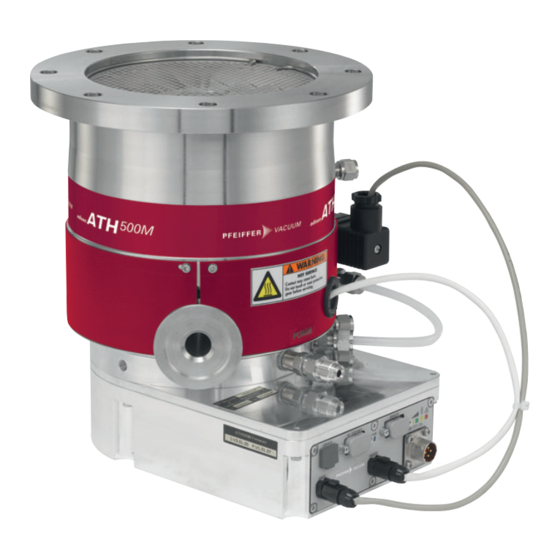
Product description 4.2 Human/Machine Interface Fig. 1: Description of an M version ATH 500 pump 1 Inlet flange (high vacuum) Control interface 2 Splinter shield Neutral gas purge (50 sccm) (1/8 BSPP fe- male equipped with a filter) 3 WATER IN/WATER OUT connections Exhaust flange (PUMP EXHAUST) (1/8 NPT female) 4 Electronic drive unit... -
Page 20: Electronic Drive Unit
Product description 4.3 Electronic drive unit The magnetically levitated pump with integrated electronic drive unit is intended to be installed into and controlled by the equipment. As standard, the electronic drive unit is equipped with an RS-232/RS-485 serial link interface and RE- MOTE connector. - Page 21 Product description REMOTE connector The REMOTE connector is used to drive the START/STOP/ STANDBYfunctions to enable the remote pump status via dry contacts. Pump status indicator lights Display of the pump operating status Power supply connector Used to connect a 48 VDC power supply Heater band electrical con- Heater band power supply nector...
-
Page 22: Installation
► Strictly comply with the installation instructions described in this manual. Pfeiffer Vacuum will be released from any warranty and liability for non-compliance with installation instructions. ► Only use approved original parts from Pfeiffer Vacuum for connection to the equipment (see ac- cessories). -
Page 23: Tbl. 1: Loads Exerted On The Equipment
Installation Description of a sudden blocking scenario The kinetic energy of the rotor has to be absorbed by the installation if the pump blocks suddenly. The maximum resulting loads have been measured on a test bench by simulating the worst-case turbo pump blockage with a rotor split in two with the pump rotating at nominal speed. -
Page 24: Securing The Equipment And The Frame
Installation 5.1.2 Securing the equipment and the frame Fastening the pump to the equipment The maximum load caused by a sudden blockage must be absorbed by the pump's fastening elements. ► Design and secure the frame of the pump so that it can withstand the maximum load. ►... -
Page 25: Fig. 6: Operating Positions
Installation The manufacturer guarantees proper operation of the pump if it is used in a uniform magnetic field up to 0.5 mT. From 0.5 to 5 mT, proper operation depends on cooling and gas loads. A magnetic field ex- ceeding 5 mT can cause excessive rotor heating. In this case, suitable shielding must be provided. The standalone pump can withstand radiation levels of up to 10 The turbomolecular pump cannot evacuate at atmospheric pressure;... -
Page 26: Connecting To The Pumping Line
Installation Fig. 8: Installing the pump inlet facing up 1 Lifting table (example) Installing the pump inlet facing up When handling the pump, a lifting device appropriate for the weight of the product must be used. The weight and center of gravity vary depending on the model (see chapters “Technical data” and “Di- mensions”). -
Page 27: Pump Inlet Connection
Installation General instructions for installing the pump in the pumping line in accordance with industry best practice The inlet and exhaust connections must not put undue strain on the pumping line that could cause leak- age. 1. Wear gloves to connect and remove the pump from the equipment. 2. -
Page 28: Connecting The Water Circuit
Installation ► Connect the turbopump with an approved backing pump (see chapter "Technical data"). ► Install an isolation valve (NC) between the turbomolecular pump and the backing pump. 5.4 Connecting the water circuit To limit corrosion and clogging of the water circuit, we recommend using softened or non-aggres- sive water with the required characteristics (see chapter "Water characteristics"). -
Page 29: Connecting The Pump To The Water Circuit
Connection of the model ATH 500 M 1 WATER IN / WATER OUT (direction does not matter) Connection procedure of ATH 500 M pump model 1. Provide a water-cooling circuit and a water valve to adjust the flow. 2. Connect the water-cooling circuit to one of the connections and the other to the drainage circuit. -
Page 30: Installation Of The Air Cooling Accessory
Installation Connection of the model ATH 500 MT 1 WATER IN Water solenoid valve power supply 2 WATER OUT Connection procedure of ATH 500 MT pump model 1. Provide a water-cooling circuit. 2. Connect the cooling circuit to the connectors provided while respecting the flow direction: –... -
Page 31: Nitrogen Circuit Connection
Installation The fan requires a 48 VDC external power supply. The 48 VDC power supply proposed by the manufacturer supplies the pump and the fan. ► Tighten the 2 screws onto the fan holder. ► Wire up the fan in accordance with the marking of terminals and wires (see chapter “Connection to external supply”). -
Page 32: Installation Of The Purge Accessory
2. Adjust the inert gas pressure to obtain the desired flow (see Purge flow diagram). * Other connections are possible depending on the ordering guide (see chapter “Product concerned”). Solenoid valve equipped with a 50 sccm purge (for ATH 500 M only) This option is available depending on the pump configuration. -
Page 33: Connection Of The Air Inlet Solenoid Valve
Installation Purge set installation This accessory is available upon request. 1. Replace the M4x16 screws of the electronic drive unit with the CHC M4x30 screws and washers. 2. Remove the dust filter or plug from the purge. 3. Tighten the 1/8'' BSPP UNION fitting to the purge port. 4. -
Page 34: Check That The Installation Is Leaktight
Installation Connecting the air inlet solenoid valve to an inert gas line This solenoid valve can be connected to an inert gas line. To connect the solenoid valve to an inert gas line, the nitrogen supply must be clean and filtered and must have the characteristics required (see chapter "Nitrogen characteristics"). -
Page 35: Customer Electrical Installation Protection
Installation The pump is a class A product.In a domestic environment, this product can cause radio in- terference. In this case, users must take appropriate measures. Electrical safety The pump motor is protected against overload by the current limitation of the variable speed drive in electronic drive unit (in case of overload, the speed decreases automatically). -
Page 36: Connection To External Power Supply
Fan power cables [ 1 or blue (-) (0 V), 2 or brown (+) (48 VDC) ] 3 Mains connector ATH 500 M version (only) ► Power the purge solenoid valve with 24 VDC (power supplied by the customer). 36/78... -
Page 37: Fig. 14: Typical Electrical Wiring Diagram
Installation ATH 500 MT version (only) ► Power the heater band and the water valve. – the HEATER and VALVE connectors on the front panel of the electronic drive unit are con- nected. Turbo HEATER 24 V DC VALVE Water 48 VDC Fig. -
Page 38: Operation
Operation 6 Operation 6.1 Preliminary precautions for use WARNING Risk of poisoning when process gases are present in the atmosphere The manufacturer has no control over the types of gases used with the pump. Process gases are of- ten toxic, flammable, corrosive, explosive and/or otherwise reactive. There is a risk of serious or fatal injury if these gases are allowed to escape freely into the atmosphere. -
Page 39: Starting The Pump
Operation 6.2 Starting the pump 6.2.1 Powering on ► Set the 48 VDC power supply switch to I: the electronic drive unit boots up. – At the end of initialization, the yellow LED turns off and the green LED turns on. 6.2.2 Pumping start-up The following steps describe the use of the pump regardless of the control panel. -
Page 40: Restarting The Pump After An Emergency Equipment Stop
Operation 6.2.3 Restarting the pump after an emergency equipment stop The equipment emergency stop manages the pump stop. To restart the pump after an emergency stop, it is necessary to: 1. Make sure the pump has stopped (all LED are off). 2. -
Page 41: Powering Off
Operation Pump stop due to power failure Stopping the pump by disconnecting the mains power supply is not a normal way to stop the pump: ● Always send a ‘Stop’ order via the control panel and wait for the pump to stop rotating before starting work on the product. -
Page 42: Tbl. 3: Meaning Of Led On The Ehercat Interface
Operation Sym- LED status Display Meaning No fault on, constant light Pump is faulty. Tbl. 3: Meaning of LED on the EherCAT interface REMOTE LED status Meaning Blue on The pump is supplied with power. Yellow on The pump has not reached the selected speed. Flashing yellow The pump speed decreases, speed >... -
Page 43: Advanced Settings
The integrated heater band heats the pump to an adjustable temperature (refered to as temperature setpoint) to prevent the effects of condensation. The temperature setpoint depends on the application the pump is to be used for. Contact Pfeiffer Vacuum’s applications department for advice in choosing the correct temperature setpoint. -
Page 44: Interfaces For Control
Interfaces for control 8 Interfaces for control 8.1 Control modes This chapter describes the connections and protocols associated with each control mode. There are 4 control modes: ● HHR The pump is controlled locally from a Hand-Held Remote control (HHR), connected on the SERV- ICE connector. -
Page 45: Powering On
Interfaces for control Functions Functions ● To move to the next or previous menu, next or ● To start the pump in local mode via HHR when START previous parameter in the displayed menu. the [SET UP][REMOTE CONTROL] menu is [KEYBOARD] (see chapter 'Menu SETUP'). -
Page 46: Display Menu
Interfaces for control Display initialization The electronic drive unit performs a self-test and identifies the connected pump. ■■■■■■■■■■■■■■■■■■■■■ Boot-up time is approximately 15 seconds. ■■■■■■■■■■■■■■■■■■■■■ ■■■■■■■■■■■■■■■■■■■■■ ■■■■■■■■■■■■■■■■■■■■■ ■■■■■■■■■■■■■■■■■■■■■ ■■■■■■■■■■■■■■■■■■■■■ The equipment is identified, the software release is displayed, and communication with the pump is tested. -
Page 47: Setup Menu
Interfaces for control 8.2.3 SETUP menu Selection Choice Description Initial setting ACCESS CODE 0 to 65535 REMOTE CONTROL Keyboard Choose the interface control mode. According to ordering guide. Remote hard Serial link Profibus EtherCAT STAND-BY SPEED Activate pump Stand-by speed (se- 15000 from 15000 rpm to pump lected speed) between minimum... -
Page 48: Control Via The Remote Connector
Interfaces for control 8.3 Control via the REMOTE connector NOTICE Safety of Extra-Low Voltage circuits Remote control circuits are equipped with dry contact outputs (24 V - 1 A max). Overvoltages and overcurrents can result in internal electrical damage. Users must observe the following wiring condi- tions: ►... -
Page 49: Logic Output Wiring
Interfaces for control +15 V 13, 14 Fig. 17: Remote connector: control by dry contacts A Internal wiring Wiring from customer's side Contact Function S3 (13-5) Contact closed: Stand-by speed is selected. Stand-by Contact open: pump rotation speed is the nominal speed. S4 (14-5) Contact closed: the pump starts. -
Page 50: Command Via The Rs-232/Rs-485 Serial Link
Interfaces for control Contact Function Fault ● The 'fault' contact closes when a fault appears (external, temper- ature, motor chassis, etc.). ● The contact is open in the absence of faults. Stand-by ● The 'stand-by' contact is closed when the stand-by mode is acti- vated. -
Page 51: Communication Protocol
Interfaces for control Assignment RS-485: V- RS-485: V+ The user must use shielded links and connections in compliance with EMC and electrical safety stand- ards. RS-232 connection A computer manages a single pump (P1) using the RS-232 link via the RS-232/RS-485 connector. RS-485 connection A computer manages several pumps (P1, P2, Pn, etc.) using the RS-485 serial link via the RS-232/ RS-485 connector This parallel wiring allows communication between the pumps even if a pump is dis-... -
Page 52: Command List
Interfaces for control Responses Header character Pump address Respons End character yyyxxxabc <CR> If everything is OK, or specific respons to the order sent ERR0 Setting fault ERR1 Order fault ERR2 Parameter fault ERR3 Context fault ERR4 Checksum fault Example of dialog Order #005ECHON<CR>... - Page 53 Interfaces for control Order Description Functions fault set- ting LEV10 none Returns the Example: status of the #adr,nnnnn,sssss,00000,0,ccccc,eeeee,00000,0000,0000,j operating pa- j,kk,ll,mmm<CR> rameters de- nnnnn = nominal speed (min fined by SET sssss = standby speed (min 00000 = not used 0 = not used ccccc = running time of the pump (hours) eeeee = running time of the electronic drive...
- Page 54 Interfaces for control Order Description Functions fault set- ting SEL10 none Status of the Example: #adr,0,0,1,0,r<CR> options/ 0 = not used orders set 1 = not used with OPT or- r = returns the remote con- by default, the value de- trol choice pends on the pump config- uration...
- Page 55 Interfaces for control Description Functions none : order status Local Fault Serial STBY START Fieldbus Fault if HHR if status if field- if Re- if Stand- when has con- mote by mode starting, at Fault ac- trol mode is hard is activat- speed, or tivated...
-
Page 56: Operation Via Fieldbus
Internal communication 8.5 Operation via fieldbus Connecting and using Pfeiffer Vacuum turbomolecular pumps with a fieldbus system is possible when the corresponding control interface is installed on the pump (depends on the ordering guide). ► Refer to the operating instructions of the corresponding control interface (see chapter “Applicable documents”). -
Page 57: Maintenance
Maintenance 9 Maintenance 9.1 Maintenance safety instructions DANGER Risk to health posed by residual traces of process gases inside the pump Process gases are toxic and hazardous to health. They can cause poisoning and be fatal. Before dis- connecting the pump, any remaining traces of process gases must be eliminated. ►... -
Page 58: Maintenance Frequency
The initial percentage is set at 100%. When this value reaches the warning threshold, a warning is triggered: the landing bearings must be replaced. If other landings occur, the counter contin- ues to decrease to 0%. Theses landing bearings must be replaced by a Pfeiffer Vacuum service center. -
Page 59: On-Site Maintenance
Maintenance 9.3 On-site maintenance The pump does not require any maintenance on the customer’s premises other than the day-to-day servicing described in this manual. All other maintenance operations must be carried out by our service center. ► Clean the outer surfaces of the product using a clean, lint-free cloth and a product that will not damage the screen-printed surfaces or adhesive labels. -
Page 60: Draining The Water Circuit
Maintenance Disconnection procedure 1. Stop the pump by sending a 'Stop' order. 2. Switch off the pump by setting the power supply main switch to O. 3. Switch off the network circuit breaker of the customer's installation. 4. Disconnect the mains plug. 5. - Page 61 Maintenance Exhaust/inlet flushing 1. Close the purge connector with a plug. 2. Install the blanking plate equipped with the injector on the exhaust flange. 3. Connect the nitrogen to the gas connector provided for this purpose. 4. Flush with nitrogen by injecting a relative pressure of 120 to 150 hPa for 30 minutes.
-
Page 62: Decommissioning
All process pumps are designed for continuous operation in process gas pumping applications and should not be stopped. Pfeiffer Vacuum declines any liability for process pumps that have been stop- ped for a prolonged period of time leading to by-product condensation, powder build-up or corrosion inside the pump, nor does its warranty cover such items. - Page 63 Decommissioning ● fluoroelastomers which may break down if they are exposed to high temperatures, ● components in contact with products resulting from processes which may have been contaminat- 63/78...
-
Page 64: Malfunctions
Malfunctions 11 Malfunctions 11.1 Malfunction and fault indication Read the safety instructions for maintenance (see chapter "Maintenance safety instructions"). When a problem occurs, the user is warned by: ● Activation of the fault/warning LED ● Audible warning of the HHR (if enabled) ●... - Page 65 Malfunctions Pump is running and a fault message is displayed Message Symptom Cause Remedy Unbalance fault Electronic drive unit stops Electronic drive unit cannot ● Check that the pump is correctly fas- the motor. The air inlet sole- position the rotor. tened to the frame (see chapter “In- Bearing over- noid valve is opened.
- Page 66 Malfunctions Pump is running and a fault message is displayed Message Symptom Cause Remedy Magnetic bear- Electronic drive unit stops Rotor levitation fault ● Wait for pump rotor to stop com- the motor. The air inlet sole- pletely. noid valve is opened. ●...
-
Page 67: Service Solutions By Pfeiffer Vacuum
We are always focused on perfecting our core competence – servicing of vacuum components. Once you have purchased a product from Pfeiffer Vacuum, our service is far from over. This is often exactly where service begins. Obviously, in proven Pfeiffer Vacuum quality. - Page 68 Service solutions by Pfeiffer Vacuum 5. Prepare the product for transport in accordance with the provisions in the contamination declaration. a) Neutralize the product with nitrogen or dry air. b) Seal all openings with blind flanges, so that they are airtight.
-
Page 69: Accessories
Accessories 13 Accessories Accessory Function Type Dimension Isolation valve This isolation valve is used Manual valve see manufacturer's catalog to maintain vacuum in the pump by isolating it in the pumping line. Hand-held remote This accessory allows re- Control box with cable 114461 control mote man/machine inter-... -
Page 70: Spare Parts
Spare parts 14 Spare parts Description Version of pump Part Number Comments 24 VDC coil ATH 500 M 038066 for purge valve and air inlet valve ATH 500 MT Dust filter ATH 500 M 106229 on air inlet solenoid valve ATH 500 MT... -
Page 71: Technical Data And Dimensions
Technical data and dimensions 15 Technical data and dimensions 15.1 General Basic principles for the Technical Data of Pfeiffer Vacuum turbomolecular pumps: ► Recommendations from PNEUROP committee PN5. ► ISO 21360; 2007: “Vacuum technology - Standard methods for measuring vacuum-pump perform- ance - General description”... - Page 72 Technical data and dimensions Technical data Units ATH 500 M ATH 500 M ATH 500 MT Pumping speed Compression ratio > 2 · 10 > 2 · 10 > 2 · 10 > 8 · 10 > 8 · 10 > 8 · 10 > 1 · 10 > 1 · 10 > 1 · 10 > 2 · 10 >...
-
Page 73: 1Environmental Characteristics
Technical data and dimensions Technical data Units ATH 500 M ATH 500 M ATH 500 MT Cooling type (acces- water/(air) water/(air) water sory) Weight (Air cooling) Weight (Water cool- ing) Backing pump recom- 15 mini. 15 mini. 15 mini. mended 1) The products that have customer specificities may have different characteristics. -
Page 74: 3Nitrogen Characteristics
Technical data and dimensions 5.5 to 9 100 to 20 ppm depending on the pH Chlorides Hardness < 35 °fH (French degree) < 7 milliequivalent/L Chloride (ppm) < 350 mg/L of CaCO (calcium carbonate) Total dissolved solids < 100 mg/L LSI (Langelier saturation Index) = <... -
Page 75: Tbl. 15: Characteristics Of The 48 Vdc External Power Supply
The supply cable used with this power supply must be compatible with the pump supply voltage and current (48 VDC, 12 A). 15.3 Dimensions Dimensions (mm) max. Exh. 3 x M8 Fig. 19: ATH 500 M dimensions 1 M4 holes for ground connection Center of gravity Exh. Fig. 20: Air cooled ATH 500 M dimensions 75/78... -
Page 76: Fig. 21: Ath 500 Mt Dimensions
Technical data and dimensions Exh. 30° Fig. 21: ATH 500 MT dimensions 1 M4 holes for ground connection Center of gravity Inlet flange DN 160 ISO-F 159.3 182.5 182.2 254.9 112.6 DN 160 ISO-K 159.3 182.5 182.2 254.9 128.6 11.3 DN 160 CF-F 180.3 203.5... - Page 77 Declaration of conformity Declaration for product(s) of the type: Magnetically levitated turbomolecular pumps and integrated electronic drive unit ATH 500 M ATH 500 MT We hereby declare that the listed product satisfies all relevant provisions of the following European Directives.
Need help?
Do you have a question about the ATH 500 M and is the answer not in the manual?
Questions and answers