Advertisement
Quick Links
Advertisement

Related Manuals for Pfeiffer Vacuum Adixen A100L Series


Summary of Contents for Pfeiffer Vacuum Adixen A100L Series
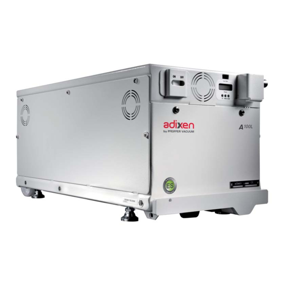
- Page 1 A100L Dry Pumps Operating instructions Operating instructions...
- Page 2 A100L dry pump Welcome Dear Customer, You have just purchased an adixen Vacuum Products dry pump. We thank you and are proud to include you as one of our customers. This product has benefited from adixen Technology’s many years of experience in semiconductor processes and dry pumping.
- Page 3 A100L dry pump This product complies with the requirements of European Directives, listed in the Declaration of Conformity contained in G100 of this operating instruction. Symbol / Label Description Warning: high temperature hazard Warning: electrical shock hazard Danger: refer to the operating instructions Power ON switch Power OFF switch MAIN POWER...
- Page 4 General contents : 119404 ANUAL P : 03 - December 2011 DITION English original version A100L Operating instructions Chapter A INTRODUCTION A 10 Operating principle A 20 Description A 30 Monitoring system A 40 Technical characteristics A 50 Accessories Chapter B START UP B 00 Safety instructions...
- Page 5 General contents : 119404 ANUAL P : 03 - December 2011 DITION English original version A100L Operating instructions Indicates a potentially hazardous situation which, if not avoided, could result in property damage. Indicates a potentially hazardous situation which, if not avoided, could result in moderate or minor injury.
- Page 6 Introduction A100L Operating instructions Detailed contents A 10 Operating principle - Multistage pump with roots technology - Tightness with environment - The pump in a pumping installation A 20 Description - Description - Interfaces - Internal equipment of the A100L pumps A 30 Monitoring system - Description...
- Page 7 A 10 Operating principle Multi-stage pump with A100L pump consists of 5 Roots type stages. roots technology The two rotors rotate without touching each other. Inlet Exhaust Stage 5 Stage 4 Stage 3 Stage 2 Stage 1 High pressure Transfer stage Transfer stage Transfer stage Low pressure...
- Page 8 A 20 Description Description The A100L pump includes a monitoring system. This pump is fully integrated in a compact and enclosed frame which includes: The control panel located on the front panel. An operating time meter showing the running time of the pump. 3 light indicators showing the pump status.
- Page 9 A 20 Description Internal equipment of The A100L pumps include a cooling circuit (water circuit). The A100L are designed for clean applications such as load lock the A100L pumps pumping, cryopump regeneration and backing of turbopumps on non- corrosive processes. Cooling circuit (principle Frequency Electrical cabinet...
- Page 10 A 30 Monitoring system Description Each pump includes a monitoring system. Main switch Main power sypply Light indicators Electrical cabinet Operating time meter Local/remote switch Motor sensors Frequency converter sensor Electrical cabinet The electrical cabinet is located at the top of the machine. It is linked to the main power supply, pump motor and electronic cabinet G 120 Electronic cabinet...
- Page 11 A 40 Technical characteristics Characteristics Units A100L A100L ES «Eco Saving» Rotation speed 6000 Peak Pumping speed l/mn 1667 mbar/ Typical ultimate pressure 6.6 10 / 5 10 / 6.6 10 7 10 / 5 10 / 7 10 Torr/ 1.2 10 / 9 10 / 1.2...
- Page 12 A 40 Technical characteristics A100L dimensions and interfacing adixen Vacuum Products - A100L - Dry Pump - Operating Instructions Alcatel Vacuum Technology France - ATH 200 User’s Manual...
- Page 13 A 40 Technical characteristics Gravity center and weight distribution Right view Front view A100L CG and Weight Distribution WEIGHT CG X CG Y CG Z FOOT DISTRIBUTION WEIGHT (Kg/ Lb) inch inch inch 103 / 135/ 325/ 152/ 5.31 12.79 5.98 48.5 52.91...
- Page 14 A 40 Technical characteristics A100L stackIing dimensions and interfacing adixen Vacuum Products - A100L - Dry Pump - Operating Instructions Alcatel Vacuum Technology France - ATH 200 User’s Manual...
- Page 15 A 40 Technical characteristics Stacking gravity center and weight distribution A100L Stacking Center of Gravity and Weight Distribution WEIGHT CG X CG Y CG Z FOOT DISTRIBUTION WEIGHT (Kg/ Lb) inch inch inch 206/ 135/ 325/ 302/ 12.8 11.9 105.8 127.9 123.4 adixen Vacuum Products - A100L - Dry Pump - Operating Instructions...
- Page 16 A 40 Technical characteristics Anti earthquake fixation dimensions for A100L pumps / 0.9 / 23.6 / 0.9 / 23.2 MAXIMUM LOADS ON GROUND & SEISMIC FIXATIONS (SEMI S2-0200 Section 19) (Newton) -129 1 x A100 -272 -183 -237 -258 -580 -454 -300 -398...
- Page 17 A 50 Accessories Anti earthquake These anti earthquake squares allow to bolt down the pump to the floor. square Description Anti earthquake square kit 109790 B 70 Anti earthquake square installation (accessory) Emergency stop This device is intented to switch off the pump power. It also has one relay contact (1 normally open) for external use.
- Page 18 A 50 Accessories Silencer kit Allows user to reduce exhaust sound level if there is no exhaust pipe connected to the pump. Description Silencer kit 066849 N2 pressurization kit Allows user to close and pressurize the pump for return to a service center.
- Page 19 Start up A100L Operating instructions Detailed contents B 00 Safety instructions - Pump installation - General - Decontamination / product dismantling - Manufacturer contact in case of emergency - Pump labels B 01 Hook-up requirements B 10 Unpacking / Handling / Storage - Precautions - Packaging dimensions - Unpacking...
- Page 20 B 00 Safety instructions Indicates a potentially hazardous situation which, if not avoided, could result in property damage. Indicates a potentially hazardous situation which, if not avoided, could result in moderate or minor injury. It may also be used to alert against unsafe practices.
- Page 21 B 00 Safety instructions General (continued) Emergency button This pump is not equipped with an EMO device because it is designed for use on process tools and integration with the process tool EMO. The pump must be protected by an EMO provided by the user equipment/ host tool, located in a non hazardous area and within 3 m (10 ft) of the pump.
- Page 22 B 00 Safety instructions General (continued) The product is supplied with the inlet and exhaust sealed. These are to prevent foreign bodies entering the pump during transport and storage. Do not remove these blanking plates until you are ready to install the product on the vacuum line.
- Page 23 B 00 Safety instructions General (continued) Safety interlock. The pump motor is protected against overload through the drive «start/ stop» and enable control circuitry of the variable speed controller. The drive start/stop includes solid state components. If hazards due to accidental contact with moving machinery or unintentional flow or liquid, gas or solids exist, an additional hardwired stop circuit is required to remove input power.
- Page 24 B 00 Safety instructions Pump labels Power supply voltage Heavy object Hot surface inside Hazardous voltage Moving parts present Seismic Tie Down Pump operating status information Located on the upper cover, this label indicates that due to its heavy weight, the product should not be handled manually, but always through appropriate handling devices.
- Page 25 B 00 Safety instructions Located on the lower part of lateral and rear panels, these labels indicate the location of the fixing holes of the anti earthquake square (accessories). Located on the upper cover, this label indicates the weight of the pump.
- Page 26 B 01 Hook-up requirements Electricity (50/60 Hz) A100L A100L Energy Saving Power supply voltage - Low voltage 200 / 208 V - 3 phases - 50/60 Hz Full load current 12 A Recommended breaker size 15 A type 10000AIC Power supply voltage - High voltage 380 / 460 V - 3 phases - 50/60 Hz Full load current...
- Page 27 B 01 Hook-up requirements N2 gas line or CDA compressed dry air for A100L Eco Saving option CDA flow 30 slm min. Pressure range 0 to 7 bar absolute (0 to 101 psi) Min. pressure / Max Pressure 2 bar / 7 bar absolute (15 / 87 psig) Consumption 30 slm min.
- Page 28 B 10 Unpacking / Handling / Storage Make sure the equipment shows no sign of transport damage. If it has Precautions been damaged, take the necessary steps to record this with the carrier and inform the manufacturer. In all cases, we recommend keeping the packaging (reusable materials) for further transport of the equipment or for prolonged storage.
- Page 29 B 10 Unpacking / Handling / Storage Handling Heavy product This product needs special handling precautions due to its weight. It should be removed from its crate only by staff trained in heavy materials handling : use the lifting rings provided with the product or tighten the pump to the handling devices .
- Page 30 B 10 Unpacking / Handling / Storage Move the pump The pump is equipped with 2 fixed wheels, 1 swivelling front wheel, a removable handle provided to move the pump easily. by pushing it Removable handle Swiveling front wheel Fixed wheel Remove the handle from its support under the frame as follows: Pull the handle along the frame rail up (1) to remove it.
- Page 31 B 10 Unpacking / Handling / Storage Storage When the pump is new, if it is going to be put into storage, keep the pump wrapped in to its protective film. Our product can be stored in the following conditions: - in a clean and dry environment, - at an ambient temperature between - 10°C and + 60°C, - for a period of 1 year maximum.
- Page 32 B 20 Positioning the pump in the pumping installation Pump performance will depend on the kind of accessories used and the quality of the mechanical connections such as the pump fittings. As these pumps are typically used in a corrosive atmosphere, their reliability will depend on proper installation and maintenance.
- Page 33 B 20 Positioning the pump in the pumping installation Lock the pump frame by adjusting the four levelling feet for resting solidly on the floor. Use a water level to check if the pump is correctly positionned in both axis. Level tool Risk of tilting Although the product meets EEC safety regulations (topple angle ±...
- Page 34 B 20 Positioning the pump in the pumping installation Pump alone Each pump is equipped with four locking screw jacks. Lock the pump by adjusting these jacks so that all four feet are resting solidly on the floor. Use a water level to check if the frame is in horizontal position in both axis.
- Page 35 B 30 Connection to the cooling circuit Risk of water leak. In case of water fitting leak or water line break, the water can reach the power supply components. The end user need to provide a water leak detector which shut off the water source.
- Page 36 B 30 Connection to the cooling circuit Connect the water pipes to the quick-connect connectors (see F10). Water cooling quick Water inlet marked «IN» (1/4 inch NPT quick female connector) connection Water outlet marked «OUT» (1/4 inch NPT quick male connector) Rear panel Pump Separately packaged...
- Page 37 B 35 ES (Energy Saving) option Inert gas N or CDA connection Nitrogen or CDA For maximum performances, a filtered dry nitrogen supply with the following characteristics is required: characteristics : 78.09 % : 20.93 % 0.01 % Flowrate A 40 Pressure range 0 to 7 bar absolute (0 to 101 psi) Min.
- Page 38 B 40 Electrical connection Electric shock hazard. The voltages and currents in use can induce electric shock. Isolate and lock out power line by switching off the main isolator before maintaining the product /or removing the cover. This main isolator has an interrupting short circuit current of 10kA. Take care! items located between the mains connection and the isolator are still under mains voltage: disconnect the mains cable from all power sources before commencing any maintenance work on the product.
- Page 39 B 40 Electrical connection Process tool electrical protection Installation protection with circuit breaker The user must supply the pump from facilities equipped with main cir- cuit breaker, curve D (IEC 60947-2), in accordance with local regula- tions and with a minimum interrupting short circuit current of 10 kA. This protection device must be in close proximity to the pump (no further than 7m (25 ft)) easily accessible by an operator, within line of sight of the pump.
- Page 40 B 40 Electrical connection Emergency button This pump is not equipped with an EMO device because it is designed for use on process tools and integration with the process tool EMO. The pump must be protected by an EMO provided by the user equipment/ host tool, located in a non hazardous area and within 3 m (10 ft) of the pump.
- Page 41 B 40 Electrical connection Low voltage electrical Max. current measured on the pump. connection 200/208 V 50/60 Hz Usual voltage Low voltage Max. current 12 A The pump is supplied with an equipped main power cable separately packaged B 10 .This last must be connected on the main power line according to the following diagram: earth not used...
- Page 42 B 50 Connection to the pumping circuit Do not expose any part of the human body to vacuum. The product is supplied with the inlet and exhaust sealed. Remove these blanking plates when you are ready to connect the product on your vacuum system.
- Page 43 B 60 Remote control plug connection (dry contacts / 16 pin plug) • Study the preliminary precautions B 00 Make sure that the main switch is off to avoid any short circuit during remote control plug disconnection/connection. Dry contact outputs are rated 50 V DC - 1 A max. Over voltage and over current can cause internal electrical damages.
- Page 44 B 60 Remote control plug connection (dry contacts / 16 pin plug) Remote control plug contact (inputs and outputs) remote control plug customer's connection 0 V DC Pump On/Off common 24 V DC = ON Pump On/Off control signal 0 V DC = OFF Pump running feedback signal Dry contact Pump running common...
- Page 45 B 60 Remote control plug connection (dry contacts / 16 pin plug) Pump working Remote control plug Pump status conditions (with main 9/10 11/12 13/14 power on) Pump running Close Close Close Close Close Pump stopped Open Close Close Close Open Pump running + warning Close...
- Page 46 B 61 Remote control plug connection (dry contacts / 19 pin plug) • Study the preliminary precautions B 00 Make sure that the main switch is off to avoid any short circuit during remote control plug disconnection/connection. Dry contact outputs are rated 50 V DC - 1 A max. Over voltage and over current can cause internal electrical damages.
- Page 47 B 61 Remote control plug connection (dry contacts / 19 pin plug) Remote control plug contact (inputs and outputs) remote control plug customer's connection Pump On/Off common 0 V DC 24 V DC = ON Pump On/Off control signal 0 V DC=OFF Dry contacts Pump running feedback signal Connection example to have a 0 - 15 V DC supply...
- Page 48 B 61 Remote control plug connection (dry contacts / 19 pin plug) Pump working conditions (with main power on) Remote control plug Pump status Pump running Close Close Close Close Close Close Close Pump stopped Open Close Close Close Close Open Close Pump running + warning...
- Page 49 B 70 Anti earthquake square installation (accessory) Pump anchorage According to the earthquake standards, the pump or stacked pumps must be fixed with the ground. The manufacturer proposes four anti earthquake squares. Accessories A 50 Anti earthquake square B 20. Position the pump installation Install the squares in regard with the four threated holes located in the...
- Page 50 Operation A100L Operating instructions Detailed contents C 10 Operating modes - Different control modes - Local control mode - Remote control mode - Selection of the pump control mode - Selection of the pump starting mode C 20 Starting mode definition «Autostart» - Pump start up - Pumping shut down C 21...
- Page 51 C 10 Operating modes Different control According to the monitoring configuration and wiring, the pump can modes Locally controlled by the main switch «Autostart». Remote controlled by remote control (dry contacts / 16 or 19 pin plug). Local control mode Starting mode via main The pump is running as a «stand-alone»...
- Page 52 C 20 Starting mode definition «Autostart» • Study the preliminary precautions B 00 The performance and operational safety of this product are guaranteed provided it is used normally in the operating conditions defined in this operating instruction manual. It is the customer’s task to: - train operators to use the product if they do not speak the language the manual is written in, - ensure operators know the safe practices to apply when using the...
- Page 53 C 21 Starting mode definition «Remote control (dry contacts / 16 or 19 pin plug)» • Study the preliminary precautions B 00 The performance and operational safety of this product are guaranteed provided it is used normally in the operating conditions defined in this operating instruction manual.
- Page 54 C 21 Starting mode definition «Remote control (dry contacts / 16 or 19 pin plug)» Speed setting Ajust the voltage on the remote control connector (pin 15-16) or B 60 or B 61 between 0 and 10 V, to adapt the rotation (pin Q-R) speed.
- Page 55 C 30 Monitoring system parameters Purpose of the sensors Sensor Function Warning water Indicates to the user that a temperature warning is temperature * present. Hazard motor The pump is stopped immediately when the temperature * hazard threshold is exceeded. * These thresholds are factory set and can not be customized.
- Page 56 Troubleshooting A100L Operating instructions Detailed contents D 00 Safety instruction related to maintenance - Pump overhaul D 10 Pump operating status information - Operation monitoring - Maintenance operations D 20 Diagnosis and troubleshooting - Pump does not start and light indicators are not lit up - Pump does not start and red light indicator is lit up - Pump is running and yellow light indicator is lit up - Pump is running and green light indicator is lit up...
- Page 57 D 00 Safety instruction related to maintenance This chapter describes the main preventive maintenance operations and provides a guide for first diagnosis in the event of an accident. Maintenance must be performed by a skilled maintenance operator trained in the relevant health and safety aspects (EMC, electrical hazards, chemical pollution, etc.).
- Page 58 D 00 Safety instruction related to maintenance Decontamination / According to the regulations 2002/96/CE about Waste of electrical and electronical equipments, and 2002/95/CE about Restriction of Hazardous product dismantling substances, the manufacturer provides a recycling paid service for the end of-life of waste electrical and electronic equipment. Any obligation of the manufacturer to take back such equipment shall apply only to complete not amended or modified equipment, using Adixen original spare parts, delivered by adixen, containing i.e.
- Page 59 D 10 Pump operating status information • Study the safety instructions related to maintenance D 00. Operation monitoring During operation, the user is warned of an operating incident by: Indicator lights on the front panel. Green on: pump is running and no problems Yellow and green on: warning Red on: hazard Hazard...
- Page 60 D 20 Diagnosis and trouble shooting Pump does not start and light indicators are not lit up INCIDENT CAUSE TROUBLESHOOTING The main switch is on position Set the main switch to position «0» The switch is in «remote» mode Check the presence of 15 or 24 The main switch is on position position.
- Page 61 D 20 Diagnosis and trouble shooting Pump is running and yellow light indicator is lit up INCIDENT CAUSE TROUBLESHOOTING water temperature Check the water supply. Water problem > 75°C Check that the water supply temperature is < 25°C. Check that the water cooling line is not clogged or has no leaks.
- Page 62 Maintenance instructions A100L Operating instructions Detailed contents E 11 Safety instructions for pump releocation E 12 Draining of the water cooling circuit - Draining E 14 Disconnecting the pump from the installation - Turning off the pump - Disconnecting the facilities - Disconnect the pump from the installation E 15 Shipping procedure...
- Page 63 E 11 Safety instructions for pump relocation Maintenance must be performed by a skilled maintenance operator trained in the relevant health and safety aspects (EMC, electrical hazards, chemical pollution, etc.). Isolate the product from all energy sources (mains electricity, compressed air, water, gas, etc.) before starting work.
- Page 64 E 12 Draining of the water cooling circuit D 00 and E 11 Study the precautions for first use Draining Stop the pump and wait its cooling. Then, stop the water supply. Compressed air Rear panel Water IN 1/4 NPT Water OUT 1/4 NPT Water IN...
- Page 65 E 14 Disconnecting the pump from the installation D 00 and E 11 Study the precautions for first use Turning off the pump Turn off the pump, turn the main switch to “0”. Turn off the customer’s main circuit breaker and lock out tag out per customer facility procedures.
- Page 66 E 15 Shipping procedure Located on the upper cover, this label warns the user against possible risk of injury due to any hand contact with hot surfaces. It states that protective gloves should be used before performing any intervention. Before shipping any pumps, it is required: To drain water to avoid hoses freezing up during shipment E 12.
- Page 67 Maintenance components A100L Operating instructions Detailed contents F 00 Spare parts - Instruction of use - Replacement of parts and use of non genuine parts F 10 First level of spare parts...
- Page 68 F 000 Spare parts - Instructions of use Replacement of parts Our products are designed to comply with current EC regulations and guarantee optimal operating conditions with maximum and use of non genuine safety conditions for the user. parts Any modification of the product made by the user is liable to lead to non-compliance with the regulations, or even to put into doubt the performance of the product and the user’s safety.
- Page 69 F 10 First level of spare parts Description The pressurization kit includes : 107956S Centering ring DN50 O’ring ISO KF DN50 Quick connect clamp DN50 Equipped inlet blank off fl ange Centering ring DN25 O’ring ISO KF DN25 Quick connect clamp DN 20/25 Outlet blank off fl...
- Page 70 Appendix A100L Operating instructions Detailed contents G 100 Declaration of conformity G 120 Electrical schematic G 200 Safety questionnaire...
- Page 71 G 100 adixen Vacuum Products - A100L - Dry Pump - Operating Instructions Alcatel Vacuum Technology France - ATH 200 User’s Manual...
- Page 72 G 120 Electrical schematic General electrical schematic A100L - Low voltage see section B60 adixen Vacuum Products - A100L - Dry Pump - Operating Instructions Alcatel Vacuum Technology France - ATH 200 User’s Manual...
- Page 73 G 120 Electrical schematic General electrical schematic A100L - High voltage see section B60 adixen Vacuum Products - A100L - Dry Pump - Operating Instructions Alcatel Vacuum Technology France - ATH 200 User’s Manual...
- Page 74 G 120 Electrical schematic General electrical schematic A100L - Eco Saving - Low voltage see section B60 adixen Vacuum Products - A100L - Dry Pump - Operating Instructions Alcatel Vacuum Technology France - ATH 200 User’s Manual...
- Page 75 G 200 Safety questionnaire Procedure for returning adixen products You wish to return an adixen product for maintenance. The equipment will be dismantled and possibly cleaned by a technician from our Service Centre. In compliance with European Community’s L360 directives, French labor code L231 - R231 and Federal OSHA Safety Standard 1910-1200, adixen Vacuum Products requires this form to be completed to preclude the potential health risk to its service personnel that can occur when receiving, disassembling, or repairing potentially contaminated products.
- Page 76 G 200 QUESTIONNAIRE DE SECURITE SAFETY QUESTIONNAIRE Ce questionnaire est téléchargeable sur le site : www.adixen.com This questionnaire can be downloaded from: www.adixen.com Procédure de retour des produits adixen (Ce formulaire ne peut être rempli et signé que par une personne habilitée) Procedure for returning adixen products (This questionnaire is only to be filled in and signed by an authorized person) SOCIETE - COMPANY...
- Page 77 RS 232 / RS 485 Network interface for A100/A180L dry pumps PTION CCESSORY adixen Vacuum Products - A100L - Dry Pump - Operating Instructions...
- Page 78 Contents RS 232 / RS 485 / Network interface operating instructions According to the product configuration, this fonctionality could be in option or accessory available. This manual must be used in complement of the A100L/ A180L pump operating instructions. Chapter B START UP B 85 RS 232 / RS 485 / Network interface installation...
- Page 79 B 85 RS 232 / RS 485 / Network interface installation • Study the preliminary precautions B 00 Preliminary operations Disconnect pump from electrical connection E 14 § turning off the pump. RS 232 / RS 485 / Loosen and remove the 4 M4x8 Chc screws holding the network Network interface blank off plate on the pump rear panel.
- Page 80 B 95 RS 232 / RS 485 link wiring When units containing control circuits are equipped with dry contact outputs, it is the responsability of the customer to use these outputs in compliance with extra low voltage installation and safety standards (SELV) •...
- Page 81 B 95 RS 232 / RS 485 link wiring Plug wiring 9-pin male DB connector RS 232 / RS 485 (Reception data) (RS 232) RD TD (Transmission Data (RS 232) GND (Ground) V(+) (RS 485) V(-) (RS 485) Examples of possible connection RS 232 serial link with a single monitoring system...
- Page 82 C 55 Use of the RS 232 serial link Controlling the unit The controls are used to manage information relative to the working pump. The pumping remote controls are however managed as a pumping using the priority. serial link Instruction syntax The control <CR>...
- Page 83 Pfeiffer Vacuum stands for innovative and custom vacuum Pfeiffer Vacuum stands for innovative and custom vacuum Leading. Dependable. Leading. Dependable. Customer Friendly. Customer Friendly. solutions worldwide. For German engineering art, competent solutions worldwide. For German engineering art, competent advice and reliable services.
- Page 84 A100L Dry Pumps Operating instructions Operating instructions...
- Page 85 C 55 Use of the RS 232 serial link List of controls List of controls Order Paramater Response Action • Specifies the address of the device for networking. adr = address of the device before the command OK or ERR2 aaa = new address of the device condition : 000...
- Page 86 C 55 Use of the RS 232 serial link List of controls (continued) Order Paramater Response Action • Returns the state of the parameters defined by OPT (continued) Separator character None 30 to 43 Reserved Carriage return • Defines the internal operating parameters. Example: #adrSETXXYZZZZ<CR>...
- Page 87 C 55 Use of the RS 232 serial link List of controls (continued) Order Paramater Response Action Value • Returns the status of the internal dynamic parameters for RS232 and RS485 (continued). 31-33 Reserved Separator character 35-37 Reserved Separator character 39-42 Reserved 0000...
- Page 88 C 55 Use of the RS 232 serial link List of controls (continued) Response Order Paramater Action • Defines the maintenance time. Example: #adr,TPEXXYYYY<CR> XXX = 00 : Run time 01 : Full overhaul 02 : Reserved XXYYYY OK or ERR2 03 : Reserved 04 :...
- Page 89 Pfeiffer Vacuum stands for innovative and custom vacuum Pfeiffer Vacuum stands for innovative and custom vacuum Leading. Dependable. Leading. Dependable. Customer Friendly. Customer Friendly. solutions worldwide. For German engineering art, competent solutions worldwide. For German engineering art, competent advice and reliable services.
Need help?
Do you have a question about the Adixen A100L Series and is the answer not in the manual?
Questions and answers