Table of Contents
Advertisement
Quick Links
Advertisement
Table of Contents

Related Manuals for Insportline Agneto


Summary of Contents for Insportline Agneto
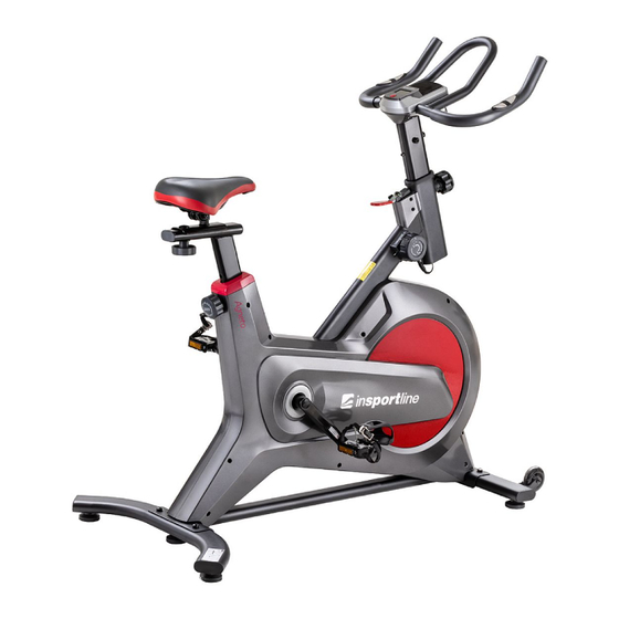
- Page 1 USER MANUAL – EN IN 20070 Indoor Spinning Bike inSPORTline Agneto...
-
Page 2: Table Of Contents
CONTENTS SAFETY INSTRUCTIONS ........................3 IMPORTANT NOTES ..........................3 DIAGRAM ..............................5 PARTS LIST ............................6 ASSEMBLY ............................. 8 RESISTANCE ADJUSTMENT ......................11 PEDAL ADJUSTMENT .......................... 11 LEVELING AND TRANSPORT ......................13 CONSOLE ............................. 13 USE ............................... 14 CORRECT BODY POSTURE ....................... 15 MAINTENANCE ............................ -
Page 3: Safety Instructions
SAFETY INSTRUCTIONS • To ensure the best safety of the exerciser, regularly check it on damages and worn parts. • If you pass on this exerciser to another person or if you allow another person to use it, make sure that that person is familiar with the content and instructions in these instructions. •... - Page 4 • Be sure to set up the exerciser in a dry and even place and always protect it from humidity. If you wish to protect the place particularly against pressure points, contamination, etc., it is recommended to put a suitable, non-slip mat under the exerciser. •...
-
Page 5: Diagram
DIAGRAM... -
Page 6: Parts List
PARTS LIST Description Description Front stabilizer Bushing Crank cover Φ25 * 7 Nut M8*H5.5*S14 Stabilizing foot ф43*14*M8*25 Nut M10*1.25*H7.5*S14 End cap PT70*30*20 39 L/R Crank Screw M6*12*S5 40 L/R Pedal Screw ST4.2*16*Φ8 Bearings 608ZZ Transport wheels Φ71*Φ19*24 Screw ST4.2*19*Φ8 Screw Φ7.8*30*M6*15*S5 43 L/R Belt cover Screw M8*20*S6... - Page 7 Fixing shaft Pulse sensor Screw ST4.0*19*Φ11 Flywheel Plug Φ12*11*Φ3 Flywheel Axle Handlebar post Meter Screw M5*8*Φ10 Trunk cable Screw M8*16*S6 Sensor cable Nut M12*1*H5*S19 Washer Handlebar Tension knob bracket Bushing Φ25*16 Wave washer d17*Φ22*0.3 Foam grip Φ23*3*420 Washer d5* Φ 10*1.0 Main frame Crank cover Washer d5*Φ13*1...
-
Page 8: Assembly
ASSEMBLY STEP 1 Attach the front and rear stabilizer (1 and 12) to the main frame (81) with 4 screws (9), 4 spring washers (10) and 4 washers (11). Fasten with wrench (B). Attach the left pedal (40L) to the left crank (39L). Screw the pedal with your hand counterclockwise. Then tighten with a wrench (95). - Page 9 STEP 2 Pass the cable (88) through the handle post (74). Attach the handles (78) to the handle post (74) with 3 screws (76), 3 washers (11), tighten with Allen key (A) (B). Unscrew the knob (13) from the main frame (81) and insert the handle post (74) with the cable (88) into the main frame (81).
- Page 10 STEP 3 Attach the saddle slider (30) to the saddle post (31) and secure with the washer (33) and knob (34).
-
Page 11: Resistance Adjustment
RESISTANCE ADJUSTMENT 1. Resistance: To increase the load, turn the knob (52) towards (+) in the A direction. Lower the load by turning the knob (52) towards (-) direction B. 2. Emergency brake: In case of danger press the brake (19). The device stops immediately. PEDAL ADJUSTMENT If the pedals are too tight, press the buckle and pull the strap up. - Page 12 SEAT AND HANDLE HEIGHT ADJUSTMENT You can adjust the saddle up / down, forward / backward 1. Height To adjust the height of the seat post (31), loosen the knob (13) and adjust the desired height. Then lock with the knob (13) (A) 2.
-
Page 13: Leveling And Transport
LEVELING AND TRANSPORT For your own safety and the long lifespan of the machine, it is essential that the machine is stable. Adjust the stability with the adjustable feet (3) under the front and rear stabilizer (1 and 12). To adjust, turn the feet (3) clockwise or counterclockwise. To move, make sure the handles (78) are properly locked. -
Page 14: Use
FUNCTIONS TIME (TMR) Training time SPEED (SPD) Current speed DISTANCE (DST) The distance traveled during training CALORIES (CAL) Calories burned PULSE (PUL) Heart rate if you hold the pulse plates SCAN The console displays all measured values BATTERY The console is powered by 2 AAA batteries. If the display is difficult to read, replace the batteries. Never mix new and old batteries or other types of batteries. -
Page 15: Correct Body Posture
who want to burn excess calories. Regular breathing, regular exercise, reasonable tempo, and balanced diet can lead to your desired results. CORRECT BODY POSTURE When training, keep your body upright, or you can learn your hand on your forearms. During pedaling, you should not have your legs fully extended. -
Page 16: Terms And Conditions Of Warranty, Warranty Claims
TERMS AND CONDITIONS OF WARRANTY, WARRANTY CLAIMS General Conditions of Warranty and Definition of Terms All Warranty Conditions stated hereunder determine Warranty Coverage and Warranty Claim Procedure. Conditions of Warranty and Warranty Claims are governed by Act No. 89/2012 Coll. Civil Code, and Act No. - Page 17 is eligible to require a compensation for all the costs arising from the repair. The cost shall be calculated according to the valid price list of services and transport costs. If the Seller finds out (by testing) that the product is not damaged, the Warranty Claim is not accepted. The Seller reserves the right to claim a compensation for costs arising from the false Warranty Claim.
Need help?
Do you have a question about the Agneto and is the answer not in the manual?
Questions and answers