
Related Manuals for Lincoln SKF ContiMaster


Summary of Contents for Lincoln SKF ContiMaster
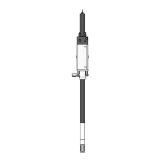
- Page 1 Assembly instructions ContiMaster following machinery directive 2006/42/EC Hydraulically driven barrel pump 509-33996-1 951-171-037-EN Version 02 2017/10/27...
-
Page 2: Ec Declaration Of Incorporation Following Machinery Directive 2006/42/Ec
EC Declaration of incorporation EC Declaration of incorporation following machinery directive 2006/42/EC, annex II, part 1 B The manufacturer, SKF Lubrication Systems Germany GmbH, Walldorf Facilities, Heinrich-Hertz-Straße 2-8, D - 69190 Walldorf, hereby declares that the partly completed machinery Designation: Hydraulically driven barrel pump to supply lubricants Type: ContiMaster... -
Page 3: Legal Disclosure
Legal disclosure Legal disclosure Manufacturer Training courses Disclaimer SKF Lubrication Systems Germany GmbH In order to provide a maximum of safety and The manufacturer shall not be held respon- economic viability, SKF carries out detailed sible for damages caused by: Manufacturer's facilities training courses. -
Page 4: Table Of Contents
Table of contents Table of contents EC Declaration of incorporation following machinery directive 2006/42/EC, ..................2 Legal disclosure ...................... 3 Explanation of symbols, signs and abbreviations ..........6 Lubricants ................... 16 Safety instructions .................8 General information ................16 General safety instructions ..............8 Selection of lubricants ................16 General behaviour when handling the product ........ - Page 5 Table of contents Shutdown and disposal ............... 41 Initial start-up ................26 13.1 Temporary shutdown ................41 Inspections prior to initial start-up .............26 13.2 Final shutdown and disassembly ............41 Inspections during initial start-up ............26 13.3 Disposal ....................41 Operation ..................27 Spare parts ................. 42 Cleaning ..................
-
Page 6: Explanation Of Symbols, Signs And Abbreviations
Explanation of symbols, signs and abbreviations Explanation of symbols, signs and abbreviations The following abbreviations may be used within these instructions. Symbols within safety notes mark the kind and source of the hazard. General warning Suspended load Risk of falling Hot surfaces Unintentional intake Crushing hazard... - Page 7 Explanation of symbols, signs and abbreviations Abbreviations and conversion factors regarding °C degrees Celsius °F degrees Fahrenheit approx. approximately Kelvin Ounce i.e. that is Newton fl. oz. fluid ounce etc. et cetera hour inch poss. possibly second pounds per square inch if appl.
-
Page 8: Safety Instructions
1. Safety instructions 1. Safety instructions 1.2 General behaviour when handling the 1.1 General safety instructions ○ Responsibilities for different activities product ○ The owner must ensure that safety infor- must be clearly defined and observed. ○ Keep unauthorized persons away. mation has been read by any persons en- Uncertainty seriously endangers safety. -
Page 9: Intended Use
1. Safety instructions ○ in areas with aggressive or corrosive ma- ○ Remedy occurring faults in the frame of terials (e.g. high ozone pollution) responsibilities. Immediately inform your superior in the case of faults beyond your ○ in areas with harmful radiation (e. g. ion- competence. -
Page 10: Reference On Pressure Equipment Directive 2014/68/Eu
1. Safety instructions 1.6 Modifications of the product 1.5 Reference on Pressure Equipment 1.8 Inspections prior to delivery Directive The following inspections were carried out Unauthorized conversions or modifica- 2014/68/EU prior to delivery: tions may result in unforeseeable impacts Because of its performance data the product on safety. -
Page 11: Markings On The Product
1. Safety instructions 1.11 Notes related to the type identification 1.10 Markings on the product plate The type identification plate states important Warning of unintentional intake SKF Lubrication Systems Germany GmbH characteristics such as type designation, or- der number, and regulatory characteristics. Sach-Nr. -
Page 12: Persons Authorized To Operate The Pump
1. Safety instructions 1.13 Briefing of external technicians 1.12 Persons authorized to operate the 1.15 Operation pump Prior to commencing the activities, external The following must be observed during technicians must be informed by the opera- commissioning and operation. 1.12.1 Operator tor of the company safety provisions, the ○... -
Page 13: Transport, Installation, Maintenance, Malfunctions
1. Safety instructions 1.17 Transport, installation, maintenance, malfunctions, repair, shutdown, disposal. ○ Ensure through suitable measures that ○ All relevant persons must be informed movable or detached parts are immobi- of the activity prior to starting any work. lized during the work and that no limbs Observe the precautionary operational can be caught in between by inadvertent measures and work instructions. -
Page 14: Initial Commissioning / Daily Start-Up
1. Safety instructions ○ All components used must be designed 1.18 Initial commissioning / daily start-up 1.19 Cleaning ○ Risk of fire and explosion when using Ensure that: according to the maximum operating pressure and the maximum respectively ○ All safety devices are completely available inflammable cleaning agents. -
Page 15: Residual Risks
1. Safety instructions 1.20 Residual risks Residual risk Possible in life cycle Prevention/ remedy Personal injury/ material damage due to Keep unauthorized persons away. No people may remain under suspended loads. Lift A B C G H K falling of raised parts parts with adequate lifting devices. -
Page 16: Lubricants
2. Lubricants 2. Lubricants 2.1 General information 2.3 Material compatibility 2.2 Selection of lubricants Lubricants are used specifically for cer- Lubricants must generally be compatible SKF considers lubricants to be an element tain application purposes. In order to fulfil with the following materials: of system design. -
Page 17: Ageing Of Lubricants
2.Lubricants 2.5 Ageing of lubricants Only lubricants specified for the Due to the multitude of possible product (see chapter Technical additives, individual lubricants, After a prolonged downtime of the machine, data) may be used. Unsuitable which according to the manu- the lubricant must be inspected prior to lubricants may lead to a failure of facturer's data sheets fulfil the... -
Page 18: Overview, Functional Description
3. Overview, functional description 3. Overview, functional description Overview, functional description Fig. 1 1 Oscillating cylinder The oscillating cylinder is connected to the hy- draulic system and drives the pump. 2 Flow control valve The flow control valve serves to adjust the volume flow rate of the hydraulic oil flowing into the pump. - Page 19 3. Overview, functional description Overview, functional description Fig. 2 5 Pump tube The lifting strokes of the oscillating cylinder are carried out by the pump tube as a supply motion. 6 Suction port Serves to take in the lubricant. During operation the suction port is in the ma- terial to be supplied.
-
Page 20: Technical Data
4. Technical data 4. Technical data 4.1 Mechanics Admissible operating temperature range of the pump -40 °C to +80 °C The specified operating temperature range of the pump presupposes the suitability of the lubricant or hydraulic oil used for the respective actually existing operating temperature. - Page 21 4. Technical data ContiMaster pump tube Part number Length Output Material to be pumped Version 84999 Legend Length in mm Output in cc (per double stroke) Material that can be pumped G = grease (special material only upon prior release by the pump manufacturer) Version a = shovel piston with plunger-in-bushing style piston | b = shovel piston with packed pistons | c = ball style valve (short form) / e = flat check valve 951-171-037...
-
Page 22: Delivery, Returns, And Storage
5. Delivery, returns, and storage 5. Delivery, returns, and storage 5.1 Delivery 5.2 Returns ○ possibly in the original product packaging After receipt of the shipment, check the Clean all parts and pack them properly (i.e. shipment for damage and completeness following the regulations of the recipient ○... -
Page 23: Installation
6. Installation 6. Installation 6.1 General information Only qualified technical personnel may install In case of new systems depend- the products described in these Instructions. ing on the overall system and During assembly pay attention to the the local ambient conditions following: there may be required further ○... -
Page 24: Minimum Assembly Dimensions
6. Installation 6.3 Minimum assembly dimensions Ensure sufficient space for maintenance work or for attachment of further components by leaving a free space of at least 100 mm into each direction in addition to the stated dimensions. Minimum assembly dimensions Fig. 3 951-171-037 - 24 - Version 02... -
Page 25: Adjusting The Volumetric Flow Rate
6. Installation 6.4 Adjusting the volumetric flow rate Adjusting the volumetric flow rate Fig. 4 To set the mode proceed as follows: • Remove the protective cap (2a). The number of double strokes per minute is set via the volu- •... -
Page 26: Initial Start-Up
7. Initial start-up 7. Initial start-up In order to warrant safety and function, a person assigned by the operator must carry out the following inspections. Immediately eliminate detected deficiencies. Deficiencies may be remedied by an authorized and qualified specialist only. Start-up check list 7.1 Inspections prior to initial start-up Mechanical and hydraulic connections carried out correctly... -
Page 27: Operation
8. Operation 8. Operation SKF products operate automatically to the greatest possible extent. Basically, activities during standard op- eration are limited to a timely refilling of lubricant. 951-171-037 Version 02 - 27 -... -
Page 28: Cleaning
9. Cleaning 9. Cleaning CAUTION Personal injury Steam jet and high pressure cleaners must not be used for direct cleaning of gaskets and flexible parts of the product. Performance of cleaning, required personal protective equipment, cleaning agents and devices following the valid operational regu- lations of the operator. -
Page 29: Maintenance
10. Maintenance Maintenance Regular and appropriate maintenance is a prerequisite to detect and clear faults in time. The specific timelines have to be determined, verified at regular intervals and adapted, if necessary, by the operator based on the operating conditions. If needed, copy the table for regular maintenance activities. All activities address to maintenance specialists with special knowledge of hydraulics. -
Page 30: Troubleshooting
11. Troubleshooting Troubleshooting Fault table 1 Fault Possible cause Remedy Check and, if necessary, adapt adjustment of the flow control valve respectively the pressure control valve. Check whether one of the indicated faults is present and rem- edy it in the frame of responsibilities. Pump does not run No adequate hydraulic oil supply Faults outside of your own responsibility have to be reported to... -
Page 31: Repairs
12. Repairs Repairs 12.1 Safety instructions ○ Clean the pump. The hydraulic connec- WARNING tions, the pressure control valve and the volume control valve as well as any other Risk of injury mounting places or assembly parts must Before carrying out any repair work, be free from contamination. -
Page 32: Tools And Accessories
12. Repairs 12.2 Tools and accessories The following tools and equipment are nec- If no tightening torques are stat- essary to carry out the works described in ed for the respective work, apply the following. tightening torques according to Spare parts, see corresponding the screw size characteristics for chapter in these instructions 8.8 screws. -
Page 33: Replacement Of The Angled Casings
12. Repairs 12.3 Replacement of the angled Replace casings Fig. 5 casings Prior to performing work, depressurize the pump and secure it against unauthorized switch-on. • Loosen the two angled casings (4) on the screws (4a) and remove them. • Install new angled casings by means of the screws (4a) included in the scope of delivery. -
Page 34: Replacement Of The Pump Tube
12. Repairs 12.4 Replacement of the pump tube Remove casing Fig. 6 Loosen the stud bolts of the distance rods Fig. 9 • Remove the two angled casings (4) and keep them together with the screws (4a) for further use. •... - Page 35 12. Repairs • Use fork wrench AF 19/32” to loosen and Remove connecting screw Fig. 11 Pump tube Fig. 13 remove the connecting screw (12) from the piston rod. When doing so fix piston rod with fork wrench AF 7/8“. Loctite 274 •...
- Page 36 12. Repairs to mount it to the base plate of the new Mount coupling Fig. 15 Mount parts Fig. 14 pump tube with the four stud bolts (1a). Tightening torque 40 Nm ± 4.0 Nm • Coat thread of screw M30 x1,5 (10) with Loctite 274.
-
Page 37: Replacement Of Pressure-Reducing Valve And Flow Control Valve
12. Repairs 12.5 Replacement of pressure-reducing Pressure-reducing and flow control valve in the oscillating cylinder Fig. 17 valve and flow control valve • Turn flow control valve (2) with fork wrench AF 29 out of oscillating cylinder. • Turn pressure-reducing valve (3) with fork wrench AF 26 out of oscillating cylinder. -
Page 38: Replacement Of The Oscillating Cylinder
12. Repairs 12.6 Replacement of the oscillating cylin- Remove casings Fig. 18 Loosen the stud bolts of the distance rods Fig. 21 • Remove the two angled casings (4) and keep them together with the screws (4a) for further use. •... - Page 39 12. Repairs Fix the piston rod. Otherwise the piston rod might glide into Mount parts Fig. 23 Mount coupling Fig. 25 the pump tube. • Use fork wrench AF 19/32” to screw con- Loctite 274 necting screw (12) onto the piston rod of the new pump tube.
- Page 40 12. Repairs doing so fix coupling (11) with a second Mount parts Fig. 26 fork wrench AF 36 against torsion. • Use fork wrench AF 22 to verify firm seat Loctite 274 of connection lines on oscillating cylinder and retighten, if necessary. •...
-
Page 41: Shutdown And Disposal
13. Shutdown and disposal Shutdown and disposal 13.1 Temporary shutdown 13.3 Disposal Temporarily shut the system down by: Countries within the European Union Countries outside the European Union ○ Switching off the hydraulic supply system Disposal should be avoided or minimized The disposal has to be done according to the 13.2 Final shutdown and disassembly wherever possible. -
Page 42: Spare Parts
14. Spare parts Spare parts The spare parts may be used exclusively for replacement of identical defective parts. Modifications with spare parts on existing products are not allowed. 14.2 b 14.2 14.2 c 14.2 d 14.3a 14.1 14.3b 14.4 14.3c 14.3d 14.3e 14.5... - Page 43 14. Spare parts Designation Qty. Part number 14.1 ContiMaster pump assy. 509-33996-1 14.2 Oscillating cylinder assy. 235-10604-9 14.2b Flow control valve 235-13179-3 14.2c Pressure-reducing valve 235-10486-9 14.2d Hexagon socket closure plug VSTI G 2/8-ED (VA) 223-13702-3 14.3 Pumpe tube assy. 509-60245-1 14.3 a Coupling kit assy.
- Page 44 SKF Lubrication Systems Germany GmbH Walldorf Facilities Heinrich-Hertz-Str. 2-8 DE - 69190 Walldorf Phone: +49 (0) 6227 33-0 Fax: +49 (0) 6227 33-259 E-mail: Lubrication-germany@skf.com www.skf.com/lubrication 951-171-037-EN Version 02 2017/10/27...
Need help?
Do you have a question about the SKF ContiMaster and is the answer not in the manual?
Questions and answers