Table of Contents
Advertisement
Quick Links
z
Assembly Instructions
Gerotor pumps and pump units of
series 143
for SKF CircOil centralized lubrication systems
Created on:
Document no.:
Version:
Read these instructions before
installation or start-up of the
product and keep them readily
available for later consultation!
16.03.2023
951-170-251-EN
01
Advertisement
Table of Contents

Related Manuals for Lincoln SKF 143 Series


Summary of Contents for Lincoln SKF 143 Series
- Page 1 Assembly Instructions Gerotor pumps and pump units of series 143 for SKF CircOil centralized lubrication systems Created on: 16.03.2023 Document no.: 951-170-251-EN Version: Read these instructions before installation or start-up of the product and keep them readily available for later consultation!
- Page 2 Original EC Declaration of Incorporation in accordance with Directive 2006/42/EC, Appendix II Part 1 B The manufacturer hereby declares at its sole responsibility that the partly completed machinery conforms to the essential health and safety requirements of the Machinery Directive 2006/42/EC, Annex I, marked in the Annex to the EC Declaration of Incorporation as applicable and fulfilled at the time of placing on the market.
- Page 3 Appendix to Declaration of Incorporation in accordance with 2006/42/EC, Annex II, No. 1 B Description of the essential health and safety requirements according to 2006/42/EC, Annex I, which have been applied and fulfilled: Table 1 Appendix to Declaration of Incorporation No.: Essential health and safety requirement Applicable:...
-
Page 4: Masthead
SKF (U.K.) Limited, 2 Canada Close, Banbury, Oxfordshire, OX16 2RT, GBR. - North America - SKF Lubrication Business Unit Lincoln Industrial 5148 North Hanley Road, St. Louis, MO. 63134 USA - South America - SKF Argentina Pte. Roca 4145, CP 2001 Rosario, Santa Fe... -
Page 5: Table Of Contents
4.9.4 Dimensions ..............27 Table of contents 4.10 Product code ................. 29 4.11 Order example ..............30 Masthead ....................4 5. Delivery, returns, storage............31 Table of contents .................. 5 5.1 Delivery..................31 Safety alerts, visual presentation, and layout ......... 6 5.2 Return shipment .............. -
Page 6: Safety Alerts, Visual Presentation, And Layout
1. Instruction steps: These indicate a chronological sequence Safety alerts, visual of instruction steps. The numbers of the steps are in bold and are followed by a period. If a new activity follows, the presentation, and layout numbering starts again at “1.” –... -
Page 7: Safety Instructions
1.3 General behaviour when handling the 1. Safety instructions product 1.1 General safety instructions • Familiarize yourself with the functions and operation of the product. The specified assembly and operating steps and their • Putting the products into operation or operating them without sequences must be observed. -
Page 8: Foreseeable Misuse
during transport, installation, start-up, operation, maintenance, 1.9 Painting plastic components and repair and disassembly. seals The painting of any plastic components and seals of the 1.6 Foreseeable misuse products described is prohibited. Completely mask or remove Any usage of the product other than as specified in this manual plastic components before painting the main machine. -
Page 9: Note On The Type Plate
1.15 Note on EAC marking No safety markings on the product The EAC conformity marking confirms the product’s conformity with the applicable legal NOTE provisions of the Eurasian customs union. In accordance with the results of the workstation risk assessment, additional labels (e.g., warnings, safety signs, prohibition signs, or labels in accordance with CLP/GHS) are 1.16 Note on China RoHS mark to be attached by the operator if necessary. -
Page 10: Residual Risks
• All warning labels on the product are fully present, visible, and • Illegible or missing warning labels are immediately replaced undamaged 1.20 Residual risks Table 3 Residual risks Residual risk Possible in lifecycle Avoidance / Remedy Electric shock due to defective power B C D Before starting up gerotor pump units of SKF series 143, lead/mains plug... -
Page 11: Lubricants
• The lubricant’s ignition temperature has to be at least 2. Lubricants 50 kelvin above the maximum surface temperature of the components. 2.1 General information 2.6 Solid lubricants Lubricants are selected specifically for the relevant application. The manufacturer or operator of the machine should ideally Solid lubricants may only be used after prior consultation with make the selection in consultation with the supplier of the SKF. -
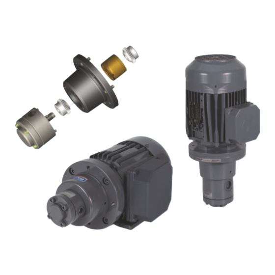
Page 12: Overview, Functional Description
3. Overview, functional description 3.1 Overview Fig. 3 Overview Legend to Figure 3: B Gerotor pump Gerotor pump Pump flange Shaft coupling C Gerotor pump unit in foot design Electric motor Terminal box for electric motor Pump foot Gerotor pump Inlet port (S), opposite the discharge port (P) A Gerotor pump unit in flange design Gerotor pump... -
Page 13: General System Description
3.2 General system description 3.3 Gerotor Pumps Fig. 4 Fig. 5 SKF CircOil centralized lubrication system SKF gerotor pump units of product series 143 are used in circulating-oil and total-loss lubrication systems in a flow rate range of 0.85 to 50 l/min. The standard permissible ambient temperature is between 0 Functional description of a gerotor pump and +40 °C. -
Page 14: Gerotor Pump Units
rotor meshes with the outer, eccentrically mounted annular performance < 0.75 kW are designed for the wide voltage gear and rotates with it. The openings between teeth arising in range. The normal coils in motors with performance ≥ 0.75 kW the suction area (Fig. -
Page 15: Technical Data
Table 4 4. Technical data Technical data The technical data for the gerotor pumps/units: see section 4.8 Value Gerotor pump unit. The technical data for the gerotor pump units: see section 3.4 <Co ntent> Gerotor pump units. Materials For connection with a frequency of 60 Hz, the speed and the Pump housing Hydraulic cast (pressure- volumetric flow are increased by 20 % (compared to the table... -
Page 16: Dynamic Viscosity, Characteristics 20 Mm 2 /S, 50 Hz
4.2 Dynamic viscosity, characteristics 4.1 Dynamic viscosity, characteristics 20 140 mm /s, 50 Hz /s, 50 Hz Fig. 9 Fig. 8 Dynamic viscosity 140 mm /s, 50 Hz Dynamic viscosity 20 mm /s, 50 Hz Legend to Figure 8: X Back pressure p [bar] Legend to Figure 8: Y Delivery rate Q [l/min] X Back pressure p [bar]... -
Page 17: Dynamic Viscosity, Characteristics 750 Mm 2 /S, 50 Hz
4.3 Dynamic viscosity, characteristics 4.4 Dynamic viscosity, characteristics 750 mm /s, 50 Hz 1000 mm /s, 50 Hz Fig. 10 Fig. 11 Dynamic viscosity 750 mm /s, 50 Hz Dynamic viscosity 1000 mm /s, 50 Hz Legend to Figure 10: Legend to Figure 10: X Back pressure p [bar] X Back pressure p [bar]... -
Page 18: Viscosity-Temperature Relationship Of Oils With Different Rated Viscosity
4.5 Viscosity-temperature relationship of NOTE oils with different rated viscosity The change in the viscosity of oils is disproportionately greater in lower temperature ranges than in higher temperature ranges. For example, an oil with a rated NOTE viscosity of 100 undergoes the following viscosity change in See also sections 4.6 Viscosity range from 2.6 to different temperature ranges at the same temperature 50 mm... -
Page 19: Viscosity Range From 50 To 2000 Mm /S
Legend to Figure 12: Temperature °C Kinetic viscosity ISO VG Viscosity class ISO VG typically corresponds to ISO VG typically corresponds to 3, 10 Spindle oils 32, 100 Normal machine oils Medium-heavy machine oils 1000 Gear oil etc. *) The values correspond to the midpoint viscosity at 40 °C in mm 4.7 Viscosity range from 50 to 2000 mm Fig. -
Page 20: Gerotor Pump Unit
4.8 Gerotor pump unit 4.8.1 Gerotor pump design, assembly holes and minimum mounting dimensions Fig. 14 Assembly drawing for gerotor pump Legend to Figure 14: Image 1 Image 2 Image 3 Image 4 Image 5 Image 6 Direction of rotation Minimum mounting dimensions AA Diameter: ØK + 20 mm Depth: A + B + 20 mm... - Page 21 Table 10 Technical data Nominal Back Permiss. Charact Nominal Speed Required Suction Pressure Design delivery pressure, operating eristic delivery power port port N (NBR) / F (FKM rate max. viscosity range curves volume consumption øPD (FPM)) [l/min] [bar] [mm²/s] [cm³/U] [rpm] [kW] øSD Order No.
- Page 22 Table 11 Technical data (continued) Nominal Dimensions [mm] delivery rate [l/min] øE øK øL øM øN øN1 Image 23.5 80 18.5 21.5 36.5 - 23.5 80 18.5 21.5 36.5 - 20.5 23.5 80 18.5 21.5 36.5 - 20.5 23.5 80 18.5 21.5 36.5 - 20.5...
-
Page 23: Gerotor Pump With Pump Flange And Shaft Coupling Design, Assembly Holes And Minimum Mounting Dimensions
4.8.2 Gerotor pump with pump flange and shaft coupling design, assembly holes and minimum mounting dimensions Fig. 15 Assembly drawing for gerotor pump with pump flange and shaft coupling Legend to Figure 15: Gerotor pump with pump flange Coupling assembly Motor connection Gerotor pump with mounting plate Image 7... - Page 24 Table 12 Technical data Design Dimensions [mm] N (NBR) / F (FKM Image G Image H Image I (FPM)) Order No. (A1) (C1) D1 (E1) F1 Frame øN øM øD size 143-13…F02D M8 31 12 deep 143-13…F05F M8 - 110 3.5 130 21.5 12 deep 143-13…H02F...
-
Page 25: Foot And Flange Designs
Table 13 Technical data (continued) Design Dimensions [mm] N (NBR) / F (FKM øPF (FPM)) Order No. øPM øPN øFM1 øM1 øSY øMZ 143-13…T03N 144.6 143-13…V02N 144.6 143-13…V03N 144.6 143-13…V03P Supplement the order No. with the code letter for the desired seal design. Seal design NBR (N) or FKM (FPM) (F). 4.9 Foot and flange designs NOTE Associated motor data: see section 15.2.3 Technical data... -
Page 26: Flange Design (Imb14)
4.9.2 Flange design (IMB14) Fig. 17 Flange design (IMB14) Legend to Figure 17: 1 Mounting plate (only for delivery rates 30, 40, and 50 l/min.) 4.9.3 Technical data Table 14 Delivery rate Back pressure, Viscosity range Characteristic Foot design Flange design max. -
Page 27: Dimensions
(continued) Table 15 Delivery rate Nominal Suction port Pressure Dimensions [mm] delivery port volume [l/min] [cm3/U] ∅PD ∅SD ∅PN ∅PF ∅FM1 ∅MZ ∅M1 0.85 0.61 G1/4 G1/4 12 deep 12 deep 0.61 G1/4 G1/4 12 deep 12 deep 1.79 G3/8 G3/8 12 deep 12 deep... - Page 28 Table 16 ∅SY øAC ∅11 136.5 37.5 ∅11 136.5 37.5 ∅11 159.5 (continued) Table 17 ∅7 1xM25x1.5 92 309.5 ∅8 1xM25x1.5 90 ∅7 1xM25x1.5 90 229.5 13.5 1xM25x1.5 123 119.5 229.5 13.5 1xM25x1.5 123 119.5 244.5 78.5 1xM25x1.5 123 119.5 229.5 13.5 1xM25x1.5 123...
-
Page 29: Product Code
4.10 Product code Product code: 1 4 3 - 1 Product series 143 Model design 1 = Motor in foot design (IMB34) 2 = Motor in flange design (IMB14) 3 = Gerotor pump + pump flange + shaft coupling (without motor) 4 = Only gerotor pump (without motor) Seal design F = FKM (FPM) -
Page 30: Order Example
Table 18 Code for pump design Code Nominal delivery rate Max. back pressure Motor drive power Permissible dynamic Frame size Number of viscosity poles [l/min] [bar] [kW] [mm²/s] T03N 40.00 4.00 20-1000 V02N 50.00 4.00 20-1000 V03N 50.00 4.00 20-750 V03P 50.00 5.50... -
Page 31: Delivery, Returns, Storage
5.5 Storage conditions for products filled 5. Delivery, returns, storage with lubricant 5.1 Delivery For products filled with lubricant, the permitted storage temperature range is: After receipt of the shipment, it must be inspected for any minimum + 5 °C [+41 °F] shipping damage and for completeness according to the maximum... -
Page 32: Assembly
• All relevant persons (e.g., operating personnel, supervisors) 6. Assembly must be informed of the activity prior to the start of work. Precautionary operational measures / work instructions must 6.1 General be observed. • Take appropriate measures to ensure that moving or detached parts are immobilized during the work and that no WARNING body parts can be pinched by unintended movements. -
Page 33: Installation Instructions
SKF gerotor pump units of product series 143 can be • SKF recommends the installation of return line or pressure installed either horizontally or vertically, depending on the filters. However, suction filters should only be used in design. conjunction with electric negative pressure switches or The gerotor pump units are available in a foot or flange contamination indicators. -
Page 34: Installation Of The Gerotor Pump With Pump Flange And Shaft Coupling
The mounting surface for the gerotor pump must be free of dust particles, machining chips, rust, and paint residue. If 9. Apply the suction and delivery fittings to the gerotor pump necessary, clean this surface prior to flanging. and tighten to the torques specified by the fitting manufacturer 10. -
Page 35: Assembly Of Gerotor Pump Unit In Foot Design, Type Im B34
4. If necessary, rotate the shaft extension of the gerotor pump The mounting surface for the gerotor pump unit must be free of again according to the position of the drive slot. dust particles, machining chips, rust, and paint residue. If 5. -
Page 36: Electrical Motor Connection
7. Apply the suction and delivery screw union to the gerotor Fig. 21 pump and tighten with the torque specified by the fitting manufacturer. 8. Check to make sure that the gerotor pump runs smoothly. 6.2.8 Electrical motor connection WARNING Electric shock Disconnect the product from the power supply before any work on electrical... -
Page 37: Lubrication Line Routing
possible, the main lubricant line should rise upward from the Fig. 22 gerotor pump unit and be ventable at the highest point on the lubrication line system. Lubricant metering devices at the end of the main lubricant line must be installed such that their outlets point upwards. If the system configuration requires that the lubricant metering devices be arranged below the main lubricant line, they should not be placed at the end of the main lubricant line. -
Page 38: First Start-Up
11. Allowing the gerotor pump unit to run until bubblefree and 7. First start-up foam-free lubricant discharges at the end of the lubricant lines. 12. Switching off the gerotor pump unit, if necessary NOTICE Dry running Damage to the pump The gerotor pump may only be commissioned and operated with an oil supply;... -
Page 39: Operation
8. Operation NOTICE Contaminated lubricant Damage to the pump Only fill using clean lubricant and an appropriate device. Contaminated lubricants lead to system malfunctions. The customer's lubricant reservoir must be filled without introducing bubbles. NOTICE Insufficient lubricant Damage due to excessively low or no lubricant The lubricant level in the lubricant reservoir should be subjected to regular visual inspection. -
Page 40: Maintenance And Repair
Precautionary operational measures / work instructions must 9. Maintenance and repair be observed. • Take appropriate measures to ensure that moving or detached parts are immobilized during the work and that no WARNING body parts can be pinched by unintended movements. Electric shock •... - Page 41 Table 19 Maintenance items <Co ntent> Centralized lubrication system operating parameters Lubricant purity Operating temperature range Lubricant fill level Gerotor pump/pump unit operating parameters Vibration Noise Pressure differential pump vs. lubricant reservoir Foaming in lubricant reservoir Leak tightness Contamination (Cooling fins on electric motor) Replacement (every 5 years) Plastic housing drive couplings...
-
Page 42: Cleaning
10. Cleaning 10.1 Basics Cleaning should be carried out in accordance with the operator's own company rules, and cleaning agents and devices and the personal protective equipment to be used should likewise be selected in accordance with those rules. Only cleaning agents compatible with the materials may be used for cleaning. -
Page 43: Faults, Causes, And Remedies
11. Faults, causes, and NOTE remedies Only original SKF spare parts may be used. Unauthorized alterations to products and the use of non-original spare parts and accessories are prohibited. WARNING Electric shock The following must be observed while working on the product: Performing work on products that have not •... -
Page 44: Gerotor Pumps And Gerotor Pump Units
11.1 Gerotor pumps and gerotor pump units Table 20 Fault table Fault Cause Remedy Gerotor pump / gerotor pump unit does not • Air inlet/lubricant below the intake • Refill lubricant, and bleed the gerotor convey or draw lubricant manifold pump/unit accordingly: see section 7. -
Page 45: Repairs
12. Repairs < WARNING Risk of injury At a minimum, the following safety measures must be taken before any repairs: • Unauthorized persons must be kept away • Mark and secure the work area • Depressurize the product • Isolate the product, and lock and tag it out •... -
Page 46: Spare Parts
14. Spare parts Spare parts may be used exclusively for replacement of identical defective parts. Modifications with spare parts on existing products are not allowed. Fig. 23 Spare parts Legend to Figure 23: 1 Coupling, complete 2 Motor 3 Pump Table 21 Gerotor pump unit Pump... - Page 47 Table 21 Gerotor pump unit Pump Coupling, complete Motor 143-12...K05J-XA+1GD 143-14...K05 995-000-357 178-S22JE-M1XA+1GD 143-11...M02H-RA+1GD 143-14...M02 995-000-356 178-S12HE-M1RA+1GD 143-12...M02H-XA+1GD 143-14...M02 995-000-356 178-S22HE-M1XA+1GD 143-11...M05K-RA+1GD 143-14...M05 995-000-357 178-S12KE-M1RA+1GD 143-12...M05K-XA+1GD 143-14...M05 995-000-357 178-S22KE-M1XA+1GD 143-11...P02K-RA+1GD 143-14...P02 995-000-358 178-S12KE-M1RA+1GD 143-12...P02K-XA+1GD 143-14...P02 995-000-358 178-S22KE-M1XA+1GD 143-11...R02M-RA+1GD 143-14...R02 995-000-359 178-S11MF-M1RA+1GD 143-12...R02M-XA+1GD 143-14...R02...
-
Page 48: Appendix
0.75 kW are efficiency class IE2 per EU standard 2009/125/EC 15. Appendix and Regulation (EU) 2019/1781, and motors with output ≥ 0.75 kW are efficiency class IE3. Special voltage versions with 15.1 IEC squirrel cage motors special coils for 50 Hz and 60 Hz networks are available for order. -
Page 49: Rating Plate
entry is 1x metric thread M25×1.5 for frame sizes 63 to 90. The frame sizes 100 to 132 have 2x M32×1.5. The terminal board always has a 6-pole design. 15.2 Rating plate Fig. 24 Rating plate Legend to Figure 24: Type of machine: Low-voltage three-phase motor Item No. -
Page 50: Voltage Code
15.2.1 Voltage code Table 23 Voltages and frequencies of different countries Voltage Voltage tolerance Voltage code and Country code (DIN EN 60034-1) certification Section A Section B UL / CSA 200 / 345 ±5 ±10 +1GF +1GF JP, HK 220 / 380 ±5 ±10 +1GP... - Page 51 Legend to Tables 23 and 24: Country code United Arab Emirates Afghanistan Argentina Australia Bolivia Brazil Canada Chile China Algeria Egypt Europe Hong Kong Indonesia Israel India Iraq Iran Japan Korea Kuwait Libya Mexico Malaysia New Zealand Panama Peru Philippines Pakistan Qatar Russia...
-
Page 52: Installation Drawing And Dimensions
15.2.2 Installation drawing and dimensions Fig. 25 Assembly drawing for three-phase motor Legend to Figure 25: I Foot design (IM B34) II Flange design (IM B14) Table 25 Squirrel cage motor dimensions [mm] Seria Motor Frame Numbe ∅M ∅N ∅PM ∅AC l no. - Page 53 Table 25 Squirrel cage motor dimensions [mm] Seria Motor Frame Numbe ∅M ∅N ∅PM ∅AC l no. size r of poles 178-S… 3.5 160 125.5 178-S… 3.5 190 136.5 178-S… 3.5 216 159.5 (continued) Table 26 Squirrel cage motor dimensions [mm] Seria l no.
-
Page 54: Technical Data
Table 27 Squirrel cage motor dimensions [mm] Seria ∅D l no. 430.5 Mounting flange acc. to DIN EN 50347 Only standard terminal box position on top is supported, right is not possible Dimension for 2nd mounting hole 15.2.3 Technical data Table 28 IEC squirrel cage motors Type... - Page 55 Table 29 Code for pump design 50 Hz Frame size Number of Flange design (with Weight Rated voltage Rated power Speed Rated current poles threaded hole) Δ Υ Δ Υ FT165 (C200) 5.50 2945 10.10 5.90 FT165 (C200) 5.50 2950 9.90 Flange with threaded hole acc.
-
Page 56: China Rohs Table
15.3 China RoHS Table Table 31... - Page 60 ® SKF and Lincoln are registered trademarks of the SKF Group. ™ eLube is a trademark of the SKF Group. © SKF Group 2023 Reprint or reproduction of the contents of this information - even in part - is permitted only with SKF's prior written consent.
Need help?
Do you have a question about the SKF 143 Series and is the answer not in the manual?
Questions and answers