Lincoln SKF FlowMaster II A Series User And Maintenance Instructions
Rotary driven electric pump (24 v dc)
Hide thumbs
Also See for SKF FlowMaster II A Series:
- Operation manual (48 pages) ,
- User and maintenance instructions (28 pages) ,
- User and maintenance instructions (20 pages)
Table of Contents
Advertisement
Quick Links
Advertisement
Table of Contents

Related Manuals for Lincoln SKF FlowMaster II A Series


Summary of Contents for Lincoln SKF FlowMaster II A Series
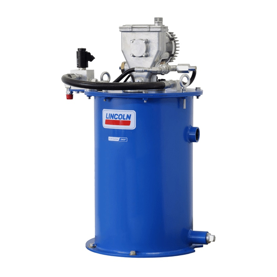
- Page 1 User and maintenance instructions FlowMaster II rotary driven electric pump (24 V DC) Model 85859, series “A” Date of issue August 2016 Form number 404696A Read manual prior to installation or use of this product. Keep manual nearby for future reference.
-
Page 2: Explanation Of Safety Signals
Contents Explanation of safety Overview signals Model 85859 is a FlowMaster II rotary driven pumping unit designed to operate a Centro-Matic lubrication system. Safety ......The pump includes motor speed control DANGER ... -
Page 3: Maintenance And Repair
Installing the pump System malfunction Refer to Filling reservoir with optional Locate unit so that electric power connection 278552 bypass manifold assem- is accessible. bly, page 5. Refer to Troubleshooting, page 6 for deter- mining common problems and solutions. 1 Mark center locations of the six holes at the bottom of the reservoir. - Page 4 8 For assembly, torque outlet connector (48) Upon reassembly, tighten to 10 ft. lbf. 4 Loosen and remove nuts (56) and and check bushing assembly (44) to (13.5 Nm). Safety unloader is preset and weighted follower plate (57) on top of the 100 ft-lbf (13.5 Nm).
- Page 5 Filling reservoir with NOTE NOTE optional 278552 bypass For ease of illing tank, pressure relief valve or Do not ill reservoir until grease level drops at pressure regulator (not provided) can be least 1 in (25 mm). manifold assembly mounted remotely. Refer to Fig.
- Page 6 Float switch Fig. 6 Fig. 5 Float switch (8) Float switch (8) 277654 consists of a nor- mally open dry-contact switch at top and a series of reed switches below. Dry contact switch controls a ‘full’ indica- tor light or alarm. Reed switches control a level gauge displaying reservoir level in 10% increments.
- Page 7 Fig. IPB 1 Ø 15- Ø 13- 9, 10 (384 mm) (352 mm) 17.6 in. (447 mm) Ø (12,7 mm) Mounting 19.3 in. 40° holes (x 6) 20° (490 mm) 33, 34 Torque to 9-10 ft.lbf 33, 34 (12-13,5 Nm) 17, 18 28.7 in.
- Page 8 Fig. IPB 2 Block and guide assembly (70) Apply two drops 242 Loctite 180 degrees apart Torque to 30–35 ft lbf * All ports are (41–47 Nm)
- Page 9 Table 2 Service Parts Item no. Description Qty. Part no. Item no. Description Qty. Part no. 1)2) Extension tube 276853 Pump check disc assembly 80206 1)2) Hose 272711 Check bushing assembly 90204 Adapter 12989 Ball check seat 10313 Adapter 12213 Gasket 31001 Outlet check assembly...
- Page 10 This page is intentionally blank.
- Page 11 This page is intentionally blank.
-
Page 12: Warranty
| lincolnindustrial.com ® SKF is a registered trademark of the SKF Group. ® Lincoln is a registered trademakr of Lincoln Industrial. © SKF Group 2016 The contents of this publication are the copyright of the publisher and may not be reproduced (even extracts) unless prior written permission is granted.
Need help?
Do you have a question about the SKF FlowMaster II A Series and is the answer not in the manual?
Questions and answers