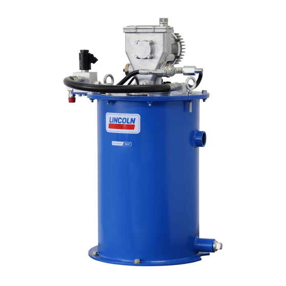
Lincoln SKF FlowMaster II A Series User And Maintenance Instructions
Rotary driven hydraulic pump
Hide thumbs
Also See for SKF FlowMaster II A Series:
- Operation manual (48 pages) ,
- User and maintenance instructions (24 pages) ,
- User and maintenance instructions (20 pages)
Table of Contents
Advertisement
Advertisement
Table of Contents

Subscribe to Our Youtube Channel
Related Manuals for Lincoln SKF FlowMaster II A Series


Summary of Contents for Lincoln SKF FlowMaster II A Series
- Page 1 User and maintenance instructions FlowMaster II rotary driven hydraulic pump series “A” Models 85731, 5 U.S. gallons, 85732, 60 lbs (27 kg), 85733, 120 lbs (54 kg), 85734, 400 lbs (181 kg), 85138, 400 lbs (181 kg), 85144 (CAT branded) Date of issue February 2023 Form number...
-
Page 2: Table Of Contents
Contents Declaration of Incorporation* ..U.K. Declaration of Incorporation* . . . Safety* ......Explanation of signal words for safety* . -
Page 3: Declaration Of Incorporation
Safety of machinery. Minimum gaps to avoid crushing of parts of the human body I, the undersigned of Lincoln Industrial Corporation, do hereby declare that the equipment specified above, in its intended use, conforms to the requirements of the above EC Directive(s). -
Page 4: U.k. Declaration Of Incorporation
I, the undersigned of Lincoln Industrial Corporation, hereby declare that the equipment specified above, in its intended use, conforms with the Essential Health and Safety Requirements of U.K. legislation Supply of Machinery (Safety) Regulations 2008 No. 1597 Annex I, Declaration of Incorporation by the time of placing it on the market. -
Page 5: Safety
Explanation of signal words Safety* CAUTION for safety* Do not operate equipment without The assembly must be installed, maintained wearing personal protective gear. and repaired exclusively by persons familiar Wear eye protection. Protective with the instructions. equipment such as dust mask, non-skid NOTE Always disconnect power source Emphasizes useful hints and... -
Page 6: Usage
Usage Overview Description of shovel action and vacuum generated in pump cylinder chamber, grease is forced into This service page details the procedure that FlowMaster II rotary driven hydraulic pump pump cylinder. Simultaneously, grease is must be followed while installing, operating is a fully hydraulically operated adjustable discharged through outlet of pump. -
Page 7: Inspection
Inspection Table 1 Pump specifications If over pressurizing of equipment is believed Hydraulic inlet flow 2 U.S. gpm (7,6 liters/min) to have occurred, contact nearest factory Operating temperature –40 to 150 °F (–40 to 65 °C) authorized warranty and service center for 300 psi (21 bar) Operating working hydraulic pressure inspection of pump. -
Page 8: Grease Output Vs. Hydraulic Input
Fig. 1 Grease output vs. hydraulic input 40 (655) 35 (573) 80 °F (27 °C) 30 (491) 20 °F (–2 °C) Grease output 25 (409) /min (cm /min) 0 °F (–18 °C) 20 (327) 15 (245) –20 °F (–29 °C) 10 (163) 5 (81) (3.7) -
Page 9: Pump Dimensions
Fig. 3 Pump dimensions 11.53 in (293 mm) 9.37 in 9.09 in (238 mm) (231 mm) 2.72 in (69 mm) ∅ 1.25 in (32 mm) Model Dimension A Dimension B 85731 25.08 in (637 mm) 13.74 in (349 mm) 85732 30.39 in (722 mm) 19.05 in (484 mm) 85733... -
Page 10: Installation And Operation
Installation and operation Install pump 1 Mount pump securely on drum cover to WARNING prevent movement or vibration during Do not operate pump without shut-off Pump was tested in lightweight oil that was operation (→ fig. 4). valve in material supply line. left in to protect pump from corrosion. -
Page 11: Operation
Operation 1 Shut off material supply line valve. NOTE 2 Turn on hydraulic pressure. Refer to Set pump manifold pressure 3 Energize solenoid on/off valve (67) and flow controls (page 12) for (→ fig. 5). instructions to adjust pressure and flow. 4 Prime pump by slowly opening shut-off See fig. -
Page 12: Set Pump Manifold Pressure And Flow Controls
Flow control valve Crankcase oil service interval Set pump manifold adjustment pressure and flow • Check oil level after every 750 hours of controls 6 Loosen hex head cap and remove from machine operation, or monthly. flow regulator (69) (→ fig. 5). •... -
Page 13: Maintenance And Repair
Maintenance and repair Disassembly 14 Loosen screws (44) holding shaft 23 Remove back-up washer (58) from tube cover (46) on pump housing (37) housing (60). (→ fig. 8, page 14). 24 Remove o-ring (59) from tube Pump 15 Remove retaining ring (48) from pump housing (60). - Page 14 Fig. 6 Fig. 8 33, 34 73, 74 Fig. 7...
-
Page 15: Crank Rod And Eccentric
Crank rod and eccentric Reciprocating tube 9 Remove retainer clip (19) from plunger link rod (20). 10 Remove o-ring (18) from plunger link 1 Loosen check seat housing (30) with rod (20). in (9 mm) hex head wrench (→ fig. 9, 11 Remove back-up washer (15) from page 16). - Page 16 Fig. 9 11 12...
-
Page 17: Assembly
Assembly Fig. 10 Crank rod and eccentric 1 Place crank rod (7) on 2 in (62 mm) diameter steel pipe, provided in tool kit 276275 (→ fig. 10). 2 Install ball bearing assembly (6) into crank rod (7). 3 Place eccentric (5) in ball bearing (6). 4 Place one end of inner retaining ring (4) on top of eccentric (5). -
Page 18: Pump
Pump 15 Thread the upper bushing and plunger 29 Install cup seal (26) with slotted side end (10) into the outlet pin (8). toward center of reciprocating tube (25) 1 Install ball (23) into lower bushing and 16 Torque to 110 to 125 in-lbf (12.4 to 14.1 Nm). (→... - Page 19 42 Position crankrod assembly (7) over top 43 Align crank rod (7) with shaft (40) 48 Install new cover gasket (36) on pump of pump housing (37) and lower into mounting hole. housing (37). pump housing (37) (→ fig. 13). 44 While aligning key (39) on shaft (40) with 49 Install pump cover (35).
- Page 20 52 Insert and thread the housing tube (60) 61 Tighten solenoid valve (67) to torque of 71 Install back-up washer (52) inside outlet into pump housing (37). 25 to 30 ft-lbf (33 to 40 Nm). pin nut (55). 53 Install hydraulic motor (72) on pump 62 Install pressure reducing valve (70) in 72 Install o-ring (53) inside outlet pin housing (37) (→...
-
Page 21: Troubleshooting
Troubleshooting Condition Possible cause Corrective action Pump does not run No pressure on gauge (64) Open shut off valve Closed supply line shut off valve • No power to solenoid valve (68) Correct electrical fault • Faulty solenoid (68) Replace solenoid (68) •... - Page 22 Fig. IPB 1 11 12...
- Page 23 Fig. IPB 2...
- Page 24 Fig. IPB 3...
-
Page 25: Parts List
Parts list Item Description Part number Quantity Item Description Part number Quantity Flat head screw ( –28 × 1 270635 Pump shaft 277397 Counter weight 272197 Retaining ring 272561 Retaining ring 270609 Ball bearing 272556 Retaining ring 270608 Shaft seal 272554 Crank eccentric 270666... - Page 26 This page left intentionally blank.
- Page 27 This page left intentionally blank.
-
Page 28: Warranty
® SKF and Lincoln are registered trademarks of the SKF Group. © SKF Group 2023 The contents of this publication are the copyright of the publisher and may not be reproduced (even extracts) unless prior written permission is granted. Every care has been taken to ensure the accuracy of the information contained in this publication but no liability can be accepted for any loss or damage whether direct, indirect or consequential arising out of the use of the information contained herein.
Need help?
Do you have a question about the SKF FlowMaster II A Series and is the answer not in the manual?
Questions and answers