schmersal PSC1 Series Installation Manual
Hide thumbs
Also See for PSC1 Series:
- Installation manual (201 pages) ,
- Installation manual (166 pages) ,
- Installation manual (177 pages)
Table of Contents
Advertisement
Quick Links
Advertisement
Table of Contents

Subscribe to Our Youtube Channel
Related Manuals for schmersal PSC1 Series


Summary of Contents for schmersal PSC1 Series
- Page 1 Installation manual PSC1 modules Series PSC1-C-10 PSC1-C-10-SDMx PSC1-E-3x...
- Page 2 Information and specifications may be changed at any time. Please obtain information on the latest version at: www.schmersal.net. K. A. Schmersal GmbH & Co. KG Möddinghofe 30 42279 Wuppertal PSC1-C-10 Installation manual V2.7...
- Page 3 Installation manual Revision history Version-No. Date Comment V 1.0 Feb 2, 2017 Release - V 2.0 May 2, 2018 Editorial changes V 2.1 Oct 31, 2018 Terminal designation CPU-ENC/ENC adapted, DC value specified for 2x Proxy 2, X22 without function with PSC1-E-(1)33-..., CANopen added, Reference to protective circuit for contactors, etc., Additional reference to derating in Chap.
-
Page 4: Table Of Contents
Installation manual Contents IMPORTANT NOTES ..................... 7 Definitions .............................. 7 Reference documents ..........................8 Abbreviations used ..........................9 SAFETY INSTRUCTIONS ..................11 Intended use ............................11 Usage in regions with UL/CSA requirement ..................11 General safety instructions ........................12 Operating and service ........................... 13 Transport/storage .......................... - Page 5 Installation manual 4.3.5.1 Classification of the I/O (IQQx) on usage as an output ............ 78 4.3.5.2 Example circuits for safe digital outputs I/O (IQQx) ............79 4.3.5.3 Overview of achievable PL for digital safety outputs ............84 CONNECTION AND INSTALLATION ..............86 General installation instructions ......................
- Page 6 Installation manual Reset behaviour ..........................128 7.3.1 Reset types and triggering element ..................128 7.3.2 Reset timing ........................129 7.3.3 Reset function ........................129 7.3.3.1 Example reset function with protection against incorrect usage ........131 LED indication ............................. 134 Parameter configuration........................135 7.5.1 Using the Memory Card ......................
-
Page 7: Important Notes
Installation manual 1 Important notes The documentation is part of the product and contains important information on integrating the module, as well as on their operation and service. The programming and parameterization of the devices are described in the programming manual. Exact knowledge and understanding of these are an essential prerequisite for installing or modifying the device function or device parameters. -
Page 8: Reference Documents
Installation manual Reference documents Description Reference Configuration of the PSC1 module with the Programming manual SafePLC2 "SafePLC2" programming system Validation report on the parameter Safety-related test with acceptance report configuration implemented and the PLC program Acceptance for general safety-related Certificate on the type test for safety applications control according to Machinery directive 2006/42/EC for product modules... -
Page 9: Abbreviations Used
Installation manual Abbreviations used Abbreviation Meaning Alternating Current Instruction List BGIA (IFA) Institute for Industrial Safety at the DGUV (German Statutory Accident Prevention Association) Here: SSI systems clock Central Processing Unit Direct Current Deutsches Institut für Normung Digital Output ECFS EtherCAT Fail Safe;... - Page 10 Pulse outputs TB(1) T bus connector (backplane bus) PELV Protective Extra Low Voltage Programmable Logic Controller SD bus Serial diagnostic bus for electronic Schmersal safety switches SDDC Safe Device-Device Communication SELV Safety Extra Low Voltage SMMC Safe Master-Master Communication SRP/CS...
-
Page 11: Safety Instructions
EC directive 2014/30/EU Cf. Appendix EC declaration of conformity Usage in regions with UL/CSA requirement The PSC1 series has a cULus approval with the following standards: Basic standard(s): UL 61010-1, 3rd Edition, May 11, 2012, Revised July 15 2015, CAN/CSAC22.2 No. -
Page 12: General Safety Instructions
Installation manual General safety instructions Safety instructions: • To prevent injury and damage, only qualified personnel are allowed to work on the device. Qualified personnel are personnel who have electrical engineering training and who are familiar with the applicable rules and standards of electrical engineering. The qualified person must become familiar with the operating instructions (cf. -
Page 13: Operating And Service
Installation manual Operating and service Prior to installing and removing the module, or disconnecting the signal wires, the module is to be electrically isolated. For this purpose, all electrically live supply wires to the device are to be switched off and it is to be checked that there is no electrical power present on the wires. During the installation and removal of the module, appropriate measures are to be taken to prevent electrostatic discharges on the external terminals and connections. -
Page 14: Device Types
Installation manual 3 Device types The series PSC1-C-10 comprises The basic devices PSC1-C-10, PSC1-C-10-SDM1, PSC1-C-10-SDM2 The expansion modules PSC1-E-31…, PSC1-E-33… The integrated communication interface (optionally with safe fieldbus) PSC1-C-10-…-FBx Basic devices The series PSC1-C-10 is a compact safety controller with optionally integrated drive monitoring for one (PSC1-C-10-SDM1) or two (PSC1-C-10-SDM2) axes. -
Page 15: Type Code
Installation manual Type code PSC1 - C - 10 - SDM1 - FB1 - MT Modbus/TCP only PNPS Additionally Supporting Profinet/Profisafe Protocol PBPS Additionally Supporting Profibus/Profisafe Protocol ECFS Additionally Supporting EtherCAT/FSOE Protocol Ethernet Based Fieldbus w Decentral Communication FB10 Ethernet Based Fieldbus wo Decentral Communication RS485 Based Fieldbus w Decentral Communication FB20 RS485 Based Fieldbus wo Decentral Communication... -
Page 16: Module Overview
Installation manual Module overview Basic modules Expansion modules Designation PSC1-C-10 PSC1-C-10-SDM1 PSC1-C-10-SDM2 PSC1-E-31-12DI-10DIO PSC1-E-33-12DI-6DIO-4RO (-FBx) (-FBx) (-FBx) Max. number of expansion modules Safe digital inputs Safe digital I/O Safe digital outputs switching / pp switching Safe analogue inputs Relay outputs (1-channel) Signal outputs Pulse outputs Integrated communication... -
Page 17: Device Characteristic Data
Installation manual Device characteristic data 3.3.1 Basic modules 3.3.1.1 PSC1-C-10 (-FBx /-MC) Type designation Device features Version of the module with following peripherals: digital inputs pulse outputs relay outputs (1-channel) pn or pp switching outputs signal outputs diagnostics and configuration interface function button 7-segment display status LED... - Page 18 Installation manual • Optional: Communication interface incl. memory card slot o Standard and safe fieldbus protocols for communication with a higher-level controller o Safe cross-communication for the exchange of data between several basic devices o Serial diagnostic bus "SD bus" o See: Section 3.3.3 Optional universal communication interface •...
-
Page 19: Tech. Characteristic Data Psc1-C-10 (-Fbx (1) /Mc)
Installation manual 3.3.1.2 Tech. characteristic data PSC1-C-10 (-FBx /MC) Safety-related characteristic data PL according to EN ISO 13849 max. PL e PFH / architecture 12.6 * 10 / KAT 4 SIL according to EN 61508 SIL 3 Proof test interval 20 years = max. - Page 20 Installation manual Environmental data Temperature 0°C … +50°C operation -25C° … +70C° storage, transport Degree of protection IP 20 Climatic class 3k3 according to DIN 60721-3 5% - 85% Minimum, maximum relative humidity (no condensation) EN 61000-6-2, EN 61000-6-4, EN 61000-6-7, EN 61800-3, EN 61326-3, EN 62061 Use of operating equipment 2000m...
-
Page 21: Psc1-C-10-Sdm1
Installation manual 3.3.1.3 PSC1-C-10-SDM1 (-FBx /MC) Type designation Device features Version of the module with following peripherals: axis encoder interfaces digital inputs pulse outputs relay outputs (1-channel) pn or pp switching outputs signal outputs diagnostics and configuration interface function button 7-segment display status LED status LEDs for inputs... - Page 22 Installation manual • Switchable safe outputs pn, pp switching for safety-related functions • Complete speed and position-related safety functions for drive monitoring as per IEC 61800-5- 2 integrated into firmware o Spatial functions for safe speed and range monitoring possible •...
-
Page 23: Tech. Characteristic Data Psc1-C-10-Sdm1 (-Fbx /Mc)
Installation manual 3.3.1.4 Tech. characteristic data PSC1-C-10-SDM1 (-FBx /MC) Safety-related characteristic data PL according to EN ISO 13849 PL e PFH / architecture 12.6 * 10 / KAT 4 SIL according to EN 61508 SIL 3 Proof test interval 20 years = max. service life General data Max. - Page 24 Installation manual Attachment Can be snapped to DIN rail Number of T-bus connector Included in the items supplied PSC1-C-10-SDM1 PSC1-C-10-SDM1 (-FBx /MC) Min. connection cross-section / AWG 0.2 mm² / 24 Max. connection cross-section / AWG 2.5 mm² / 12 Options;...
-
Page 25: Psc1-C-10-Sdm2
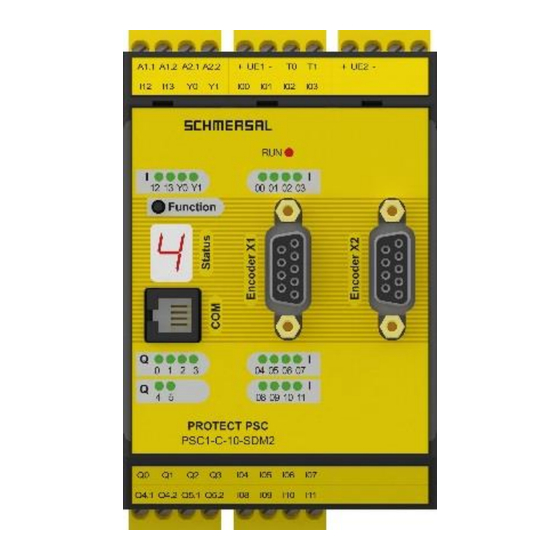
Installation manual 3.3.1.5 PSC1-C-10-SDM2 (-FBx /MC) Type designation Device features Version of the module with following peripherals: axes encoder interfaces digital inputs pulse outputs relay outputs (1-channel) pn or pp switching outputs signal outputs diagnostics and configuration interface function button 7-segment display status LED status LEDs for inputs... - Page 26 Installation manual • Switchable safe outputs pn, pp switching for safety-related functions • Parameter administration for expansion modules in the basic device • Comprehensive diagnostic functions integrated • Coded status indication via 7-segment display and status LEDs on front • Multi-function button (Quit, Start, Reset) can be operated from the front •...
-
Page 27: Tech. Characteristic Data Psc1-C-10-Sdm2 (-Fbx )
Installation manual 3.3.1.6 Tech. characteristic data PSC1-C-10-SDM2 (-FBx Safety-related characteristic data PL according to EN ISO 13849 PL e PFH / architecture 12.6 * 10 / KAT 4 SIL according to EN 61508 SIL 3 Proof test interval 20 years = max. service life General data Max. - Page 28 Installation manual Weight PSC1-C-10-SDM2 = 390 g PSC1-C-10-SDM2 (-FBx /MC) = 490 g Attachment Can be snapped to DIN rail Number of T-bus connector Included in the items supplied PSC1-C-10-SDM2 PSC1-C-10-SDM2 (-FBx /MC) Min. connection cross-section / AWG 0.2 mm² / 24 Max.
-
Page 29: Central Expansion Modules
Installation manual 3.3.2 Central expansion modules 3.3.2.1 PSC1-E-31 and PSC1-E-33 Type designation Device features Version of the module with following peripherals: PSC1-E-31/33 digital inputs 10/6 digital I/O pulse outputs signal outputs relay outputs (1-channel) status LEDs for inputs status LEDs for signaling outputs status LEDs for relay outputs 10/6 status LEDs for I/O... - Page 30 Installation manual Tech. characteristic data: PSC1-E-31 and PSC1-E-33 Safety-related characteristic data PL according to EN ISO 13849 PL e PFH / architecture 9,2 * 10 / KAT 4 + on PSC1-E-33 1-channel per relay 2 * 10 (KAT 1) 2-channel per relay 1 * 10 (KAT 4) SIL according to EN 61508 SIL 3...
- Page 31 Installation manual Mechanical data Size PSC1-E-31 = 100x115x45 (HxDxW [mm]) PSC1-E-33 = 100x115x67,5 Weight PSC1-E-31 = 300 g PSC1-E-33 = 400 g Attachment Can be snapped to DIN rail Number of T-bus connector Included in the items supplied PSC1-E-31 PSC1-E-33 Min.
-
Page 32: Optional Universal Communication Interface
Storage medium for safety-related user program Properties of the universal communication interface: • Optional version of the communication interface for the PSC1 series • The different versions can be combined. See "Possible combinations". • For more detailed information, please refer to the installation manuals for the related fieldbus modules. -
Page 33: Tech. Characteristic Data: Optional Universal Communication Interface
Installation manual 3.3.3.1 Tech. characteristic data: Optional universal communication interface Safety-related characteristic data PL according to EN ISO 13849 n.a. PFH / architecture n.a. SIL according to EN 61508 n.a. Proof test interval n.a. General data Decentral communication interfaces 2x RJ 45 (not FB10/20 variants) Fieldbus interfaces -FB1... -
Page 34: Encoder Specifications
Installation manual 3.3.4 Encoder specifications Incremental-TTL Physical Layer RS-422 compatible Signal A/B Signals with 90 degrees phase shift Max. frequency input signals 200 kHz / 250 kHz (X1, X2 / X3, X4) Connection D-SUB 9pol Sin / Cos Physical Layer RS-422 compatible Signal A/B Signals with 90 degrees phase shift... -
Page 35: Marking
Installation manual Marking The type plate is attached to the left side wall of the module and contains the following information: 3.5.1 Type plate • Type designation • Part number/item number • Serial number • Hardware release identifier • Software release identifier •... -
Page 36: Items Supplied
Programming adapter (order designation: PSC1-A-90-PROG-CABLE) • SafePLC2 software package (order designation: PSC1-A-91-SAFEPLC2) consisting of: o Licence dongle Note: Installation and programming manual, as well as the configuration software SafePLC2 can be found at products.schmersal.com PSC1-C-10 Installation manual V2.7 Page 36 of 174 Version: 57E... -
Page 37: Safety-Related Features
4 Safety-related features General layout, safety-related architecture and characteristic data The internal layout of the PSC1 series comprises two separate channels with mutual result comparison. High-quality diagnostics are undertaken in each of the two channels for fault detection. The architecture and principle of operation of the layout corresponds to category 4 in EN ISO 13849-1. - Page 38 Installation manual Characteristic data: • Max. achievable safety class SIL 3 as per EN61508 • Category 4 as per EN954-1 • Performance Level e as per EN ISO 13849-1 System structure 2-channel with diagnostics (1002) according to EN 61508 Architecture category 4 according to EN ISO 13849 Design of the operating mode "High demand"...
-
Page 39: Safety-Related Characteristic Data And Circuitry For Sensors Connected
Installation manual Safety-related characteristic data and circuitry for sensors connected The PSC1 modules have completely separated signal processing paths for each safety input. In addition, measures for obtaining the highest possible DC values are implemented. 4.2.1 Digital sensors: The digital inputs are completely redundant. The details for the categorisation, the DC and the achievable PL or SIL are listed in the following. -
Page 40: Dc Digital Sensors/Inputs
Installation manual 4.2.1.2 DC digital sensors/inputs The PSC1 modules provide wide-ranging diagnostic functions for the input sub-system. These are designed as continuous, or optional (cross-circuit monitoring using pulse detection, cross comparison, 2-channel or multiple-channel sensor with/without time monitoring, start-up test). Continuously active diagnostic functions: Cross comparison: The inputs on the PSC1 modules are in principle designed internally as dual channel. - Page 41 Installation manual Sensors / input elements with 2-pole or multiple pole contacts with time monitoring: Same check as before however with the additional monitoring of the input signals for consistency of the defined level relationships within a time window of 3 s. If the levels differ for a period > 3 s, a module alarm is triggered.
- Page 42 Installation manual For the safety-related assessment of the overall system, it is therefore possible in principle to use the following diagnostics for the input sensors: Characteristics Tests that can be configured Definition of the measure Comment of the input / operative tests element Single-channel Cyclic test stimulus by dynamic...
- Page 43 Installation manual Safety instructions: • For a safety-related assessment of the sensor sub-system, the information from the manufacturer (MTTF , PFH figures etc.) is to be used. • The DC values stated in the table are to be used conservatively and compliance with the boundary conditions (see "Comments"...
-
Page 44: Classification Of The Safe Digital Inputs
Installation manual 4.2.1.3 Classification of the safe digital inputs 4.2.1.3.1 Digital inputs I00 … 13 Digital inputs Performance Level Remark that can be achieved Suitable for all types of input elements, with / without I00 … I03 pulses, achievable PL dependent on MTTF of the input PL e I08 …... - Page 45 Installation manual 4.2.1.3.2 Digital inputs I/O (IQIx) Digital inputs Achievable Remark Performance Level Without pulse, single-channel static signal -> Signal input Without pulse, dual-channel static signal PL e At least one demand/day due to application Fault detection only on demand Without pulse, dual-channel static signal PL d Less than one demand/day due to application...
-
Page 46: Connection Examples, Digital Sensors/Safety Switch
Installation manual 4.2.1.4 Connection examples, digital sensors/safety switch Attention! Identifiers for "Xxy" terminal blocks (e.g. X14) are not printed on the terminal blocks. They are used in Section 5.6 Terminal assignment to find the individual terminals more quickly, e.g. "I00". 4.2.1.4.1 Single-channel sensor, without cross-circuit testing Single-channel sensor, without cross-circuit testing The single-channel sensor is connected to the PSC1 without test pulses, and without cross-circuit... - Page 47 Installation manual On the usage of a single-channel sensor with test pulses, one connection is connected to the test pulse output T0 or T1 of the PSC1. The pulse assignment must then also be carried out in SafePLC2. The usage of a single-channel sensor with test pulses detects: Short-circuit to the supply voltage DC 24 V Short-circuit to DC 0 V Cable break (interruption of power is safe state!)
- Page 48 Installation manual 4.2.1.4.3 Dual-channel sensor without time monitoring and without cross-circuit testing Faults are detected as a minimum on demand. The DC is medium and can be changed to the high category by using cyclic tests (start tests, operative/organisational tests) depending on the test frequency.
- Page 49 Installation manual Safety instructions: • PL d or higher according to EN ISO 13849-1 is achieved on the usage of switching elements / sensors with positively opening contacts or positive actuation according to EN 60947-5-1. • When using sensors with no positive break contacts, the "Universal Input Module" macro (group) must be used in SafePLC2.
- Page 50 Installation manual 4.2.1.4.4 Dual-channel sensor with time monitoring and cross-circuit testing By using two independent test pulse signals on the homogeneous sensor, all cross-circuits and connections to DC 24 V and DC 0 V can be detected. PL d or higher according to EN ISO 13849-1 can be achieved on: The usage of sensors / switching elements with positive actuation.
-
Page 51: Overview Of Achievable Pl For Digital Safety Inputs
Installation manual 4.2.1.5 Overview of achievable PL for digital safety inputs Type of Input Tests that can be Achievab Fault exclusion for Condition for input element sensor / configured / le PL input element input operative tests accordin element g to EN 13849-1 Input element proven in operation... - Page 52 Installation manual Type of Input Tests that can be Achievab Fault exclusion for Condition for input element sensor / configured / le PL input element input operative tests accordin element g to EN 13849-1 Short-circuit on the Connection in the switch cabinet input/signal wire or protected laying Stuck / positive opening...
-
Page 53: Sensors For Speed And/Or Position Acquisition
Installation manual 4.2.2 Sensors for speed and/or position acquisition 4.2.2.1 General safety-related layout of sensor interface for position and/or speed Different safety levels can be achieved depending on the encoder type and encoder combination. The safety assessment for the related sub-system is as follows: Sensor Sensor Sensor... -
Page 54: General Diagnostic Measures For Encoder Interface
Installation manual 4.2.2.2 General diagnostic measures for encoder interface For fault detection in the sensor system, a series of diagnostic measures are implemented in the PSC1 series depending on the encoder type selected and their combination. The measures are activated automatically with the selection of the encoder type. -
Page 55: Encoder Types And Their Combinations, Diagnostic Characteristic Data
Installation manual 4.2.2.3 Encoder types and their combinations, diagnostic characteristic data Safe Safe Safe 2-channel 2-channel sub-system Encoder A Encoder B absolute Fault exclusion 1-channel velocity direction sub-system non-dynamic position sub-system dynamic (Stand-still monitoring) ***) 1 x Proxy 1 x Proxy actuator n.a. - Page 56 Installation manual Safe Safe Safe 2-channel 2-channel sub-system Encoder A Encoder B absolute Fault exclusion 1-cahnnel velocity direction sub-system non-dynamic position sub-system dynamic (Stand-still monitoring) Resolver n.a. 95-99% n.a. 90-95% Mech. Encoder mounting 60% / SIN/COS 90-95% *) **) Code disc mounting Mech.
-
Page 57: Specific Diagnostic Measures In Relation To The Encoder Type Used
Installation manual 4.2.2.4 Specific diagnostic measures in relation to the encoder type used Encoder type Incremental SIN/COS Proximity switch 2 x count input Proximity switch 1 x count input PSC1-C-10 Installation manual V2.7 Page 57 of 174 Version: 57E... -
Page 58: Safety-Related Shutdown Thresholds, Encoder Systems For Position And Speed Acquisition
Installation manual 4.2.2.5 Safety-related shutdown thresholds, encoder systems for position and speed acquisition As a basic measure, plausibility tests between the two measurement channels A and B for speed and position on the PSC1 module are undertaken with the actual values for position and speed and tested against configured thresholds. - Page 59 Installation manual Value Value Acceleration [rev/min/s] Resolution (values in rev/min/s) Graph of acceleration resolution, rotary Acceleration [mm/s ] and [m/s ² ² Resolution (values in mm/s and m/s²) Graph of acceleration resolution, linear PSC1-C-10 Installation manual V2.7 Page 59 of 174 Version: 57E...
- Page 60 Installation manual Safety instructions: • The error can be optimised by the suitable selection of the sensor resolution for the related application. • For applications with limited resolution and/or time variance in the sampled signal, the functionality of the monitoring functions used can be improved by the usage of a mean value filter.
-
Page 61: Safety-Related Assessment Of The Encoder Types And Their Combination
4.2.2.6 Safety-related assessment of the encoder types and their combination Due to the monitoring functions implemented in the PSC1 series, in applications with encoder systems there are initially no special requirements on the internal layout of the encoder electronics, i.e. it is generally possible to use standard encoders. - Page 62 Installation manual • On the usage of compact encoders with a dual-channel internal layout, e.g. SSI + incremental/SINCOS, the instructions from the manufacturer in relation to the safety-related properties of diagnostic measures, mechanical connection and measures for the supply of power are to be followed.
-
Page 63: Safety-Related Characteristic Data And Circuitry For The Outputs
Installation manual Safety-related characteristic data and circuitry for the outputs The PSC1 modules have safe outputs of a different type. In the circuitry the related characteristic as per the description below is to be considered. 4.3.1 Characteristics of the output elements Single-channel output PSC1 and single-channel actuator without diagnostics Single-channel output PSC1 and single-channel actuator with diagnostics Single-channel output PSC1 (Q4/Q5, Q0/2_P, Q1/3_N) and dual-channel actuator... - Page 64 Installation manual Single-channel output PSC1 with internal dual-channel processing (IQQx) and dual-channel actuator with dual-channel diagnostics Dual-channel output PSC1 and dual-channel actuator with diagnostics Dual-channel output PSC1 and dual-channel actuator with dual-channel diagnostics PSC1-C-10 Installation manual V2.7 Page 64 of 174 Version: 57E...
-
Page 65: Diagnostics In The Shutdown Circuit
Installation manual 4.3.2 Diagnostics in the shutdown circuit The shutdown circuits have diagnostic functions with a fixed implementation and diagnostic functions that can be configured. Certain diagnostic functions also include the external part of the shutdown circuit. The various DC values are dependent on the usage of these diagnostic functions. 4.3.2.1 Diagnostic functions Diagnostic functions with fixed implementation: Crosswise readback of the outputs:... -
Page 66: Overview Of Dc In Relation To Selected Diagnostic Functions
Installation manual 4.3.2.2 Overview of DC in relation to selected diagnostic functions Measure Comment Usage Monitoring of outputs by one 0-90% DC dependent on the switching Monitoring of channel without dynamic test frequency electromechanical, pneumatic or hydraulic actuators / On the usage of elements for outputs increasing the switching rating (external relays or contactors),... -
Page 67: Permissible Capacitive And Inductive Load On Safe Outputs
Installation manual 4.3.3 Permissible capacitive and inductive load on safe outputs The safe outputs on the PSC1 are of an OSSD character. I.e. the outputs are shut down cyclically to test the shutdown capability and the status read back. The test on the shutdown capability is based on the following criteria / functions: After the shutdown of the output, the output voltage is allowed to be max. -
Page 68: Digital Outputs
PSC1-C-10, PSC1-C-10-SDM1, PSC1-C-10-SDM2 • PSC1-E-31-..., PSC1-E-33-... each have identical outputs. 4.3.4.1 Characteristic data of the basic outputs The PSC1 series provides different types of outputs that can be connected together either separately or in groups. Output Architecture according Remark to EN ISO 13849-1... - Page 69 Installation manual Safety instructions: • For applications with frequent demand for the safety shutdown, testing should be at short intervals, e.g. at the start of the shift, 1 x per week. However, a test should be undertaken cyclically at least 1 x per year. •...
-
Page 70: Example Circuits, Basic Outputs
Installation manual 4.3.4.2 Example circuits, basic outputs Attention! Identifiers for "Xxy" terminal blocks e.g. X21 are not printed on the terminal blocks. They are used in Section 5.6 Terminal assignment to find the individual terminals more quickly, e.g. "Q0_P". 4.3.4.2.1 Single-channel switching relay or semiconductor output without testing For interfacing to multiple phase applications or if higher current is required, external contactors can be used. - Page 71 Installation manual 4.3.4.2.2 Single-channel switching relay or semiconductor output with external device for increasing the switching rating and testing On the usage of an external device for increasing the switching rating, or downstream electromechanical, pneumatic or hydraulic components, a device for testing the complete chain and a signaling/warning device on the detection of a fault are required to achieve PL c or higher.
- Page 72 Installation manual 4.3.4.2.3 Single-channel switching relay or semiconductor output with dual-channel external circuit with testing For safety applications from PL c according to EN ISO 13849-1 it is recommended or required to operate two external shutdown elements. In addition, a device for testing the complete chain and a signaling/warning device on the detection of a fault are required to achieve PL c or higher –...
- Page 73 Installation manual Q0_P Q1_N Q2_P Q3_N Single-channel switching output Q0_P with dual-channel external circuit as combination of electromechanical element and hydraulic/pneumatic valve monitoring on two inputs Safety instructions: • Only recommended to a limited extent for safety applications! On this topic see also the information in EN ISO 13849-1 on usage and the fault exclusions necessary.
- Page 74 Installation manual 4.3.4.2.4 Dual-channel switching relay output with external monitoring - collective feedback For safety applications from PL d according to EN ISO 13849-1, two relays are used in the PSC1-C-10-x module and two external contactors. Q4.1 Q4.2 Q5.1 Q5.2 Dual-channel switching relay output with external monitoring –...
- Page 75 Installation manual 4.3.4.2.5 Dual-channel output with relay output and semiconductor output – external control circuit with monitoring For safety applications from PL d and higher according to EN ISO 13849-1. The external circuit is operated using two channels via one relay output and one semiconductor output. Each of the two external shutdown paths is monitored.
- Page 76 Installation manual 4.3.4.2.7 Dual-channel output with semiconductor output and external control circuit in PL e For safety applications from PL d and higher according to EN ISO 13849-1. The external circuit is operated using two channels via semiconductor outputs. PL e is required for the external circuit for PL e according to EN ISO 13849-1.
- Page 77 Installation manual 4.3.4.2.9 Connecting a signal output Both semiconductor outputs implemented in the PSC1-C-10-x module can be used for functional applications. The outputs are not pulsed. Connecting an signal output Applications with auxiliary outputs are not allowed for safety applications! PSC1-C-10 Installation manual V2.7 Page 77 of 174 Version: 57E...
-
Page 78: Digital Outputs I/O (Iqqx)
Installation manual 4.3.5 Digital outputs I/O (IQQx) The expansion modules PSC1-E-31-… and PSC1-E-33-… have configurable safe digital I/O (see section 3.2 Module overview). Configured as an output, this connection acts as a safe digital pp switching output (IQQx). 4.3.5.1 Classification of the I/O (IQQx) on usage as an output Classification Achievable PL Remark... -
Page 79: Example Circuits For Safe Digital Outputs I/O (Iqqx)
Installation manual 4.3.5.2 Example circuits for safe digital outputs I/O (IQQx) Attention! Identifiers for "Xxy" terminal blocks e.g. X12 are not printed on the terminal blocks. They are used in Section 5.6 Terminal assignment to find the individual terminals more quickly, e.g. "IQQ00". - Page 80 Installation manual 4.3.5.2.2 Single-channel circuit with testing On the usage of a dual-channel output (IQQx) in conjunction with an external single-channel circuit with testing. In particular, positively driven auxiliary contacts are required for electromechanical devices, or valve position signal contacts are required for this purpose for hydraulic or pneumatic components.
- Page 81 Installation manual 4.3.5.2.3 Circuit with safe shutdown circuit For safety applications from PL c and higher according to EN ISO 13849-1. The external circuit is operated directly using a dual-channel output. The achievable PL according to EN ISO 13849-1 is dependent on the usage of dynamic testing (see 4.3.2.1) as well as the PL for the subordinate device.
- Page 82 Installation manual 4.3.5.2.5 Redundant dual-channel output Suitable for PL d or higher according to EN ISO 13849-1. Usage of two outputs IQQx in conjunction with a dual-channel external circuit. 4.3.5.2.5.1 Dual-channel circuit in same group IQQ00 IQQ01 IQQ02 IQQ03 IQQ04 IQQ05 IQQ06 IQQ07...
- Page 83 Installation manual 4.3.5.2.5.2 Dual-channel circuit in different groups IQQ00 IQQ01 IQQ02 IQQ03 IQQ04 IQQ05 IQQ06 IQQ07 IQQ08 IQQ09 Redundant dual-channel outputs in different groups in conjunction with dual-channel shutdown circuit Safety instructions: • For the safety-related assessment of the output sub-system, on the usage of external elements in the shutdown circuit, e.g.
-
Page 84: Overview Of Achievable Pl For Digital Safety Outputs
Installation manual 4.3.5.3 Overview of achievable PL for digital safety outputs Output PSC1 Actuator / Category MTTF Achiev Boundary condition Fault external according actuato able PL exclusion shutdown to EN ISO accordi circuit 13849-1 ng to EN ISO 13849- Single-channel Single-channel Cat. - Page 85 Installation manual Output PSC1 Actuator / Category MTTF Achieva Boundary condition Fault external according actuato ble PL exclusion shutdown to EN ISO accordi circuit 13849-1 ng to EN 13849-1 Dual-channel Dual-channel Cat. 3 Monitori Medium Contactor and Short-circuit without Contactor, valve, ng in or high downstream actuators...
-
Page 86: Connection And Installation
Installation manual 5 Connection and installation General installation instructions It is imperative you follow the safety instructions during installation! Degree of protection IP20 Lay all signal wires for connection to the digital inputs and contact monitoring separately. Under all circumstance separate voltages of 230 V AC (120 VAC cULus) from low-voltage wires, if these voltages are used in relation to the application. - Page 87 Installation manual Safety instructions: • It is to be ensured that the power supply wires for the PSC1 and "switching wires" for the power converter are laid separately. • Signal wires and power wires for the power converter are to be laid in separate cable ducts. The distance between the cable ducts should be at least 10 mm.
-
Page 88: Installation And Mounting Psc1 Module
Installation manual Installation and mounting PSC1 module The module is only to be installed in switch cabinets that meet degree of protection IP54 as a minimum. The modules must be fastened vertically on a DIN rail Note: When used in non-closed rooms it must be ensured that the environmental conditions of the individual assemblies (see technical data) are complied with. -
Page 89: Arrangement Examples
Installation manual 5.3.1 Arrangement examples 5.3.1.1 PSC1-C-10-SDM1 + PSC1-E-31-…. + PSC1-E-33-…. PSC1-E-31-…. PSC1-C-10- PSC1-E-33-…. SDM1 5.3.1.2 PSC1-C-10-SDM2 + PSC1-E-33-…. PSC1-C-10-SDM2 PSC1-E-33-…. PSC1-C-10 Installation manual V2.7 Page 89 of 174 Version: 57E... -
Page 90: Mounting The Modules
Installation manual Mounting the modules The modules are mounted on standard C rails using a snap-action catch 5.4.1 Mounting on C rail The devices are fitted to the rail from above at an angle and snapped downward. They are removed using a screwdriver that is inserted in the slot on the catch protruding from the bottom of the device and then moved upward. -
Page 91: Mounting On Backplane Bus
Installation manual 5.4.2 Mounting on backplane bus After mounting the backplane bus, the devices can be mounted. For this purpose, the module is fitted to the connector at an angle from above and snapped to the C rail Fit module at an angle from above… …and snap down onto the C rail The backplane connection can later be enlarged. -
Page 92: Installation Of I/O Expansion
Installation manual 5.4.3 Installation of I/O expansion Note: Max. two PSC1-E-3x modules can be operated using a basic device. 5.4.3.1 Physical address configuration for the slave modules The bus address must be set on the PSC1-E-3x modules by means of the address switch. The address is set on the rear panel depending on the slot (mounting position) of the module. -
Page 93: Installation And Configuration Of Master Master (Smmc) And Master Slave (Sddc)
Installation manual Installation and configuration of master master (SMMC) and master slave (SDDC)* The SMMC communication allows to safely exchange 2 bytes of data between up to four** master devices. Communication takes place without a dedicated master for the co-ordination of the data. As such there is always an exchange of data between available bus users. -
Page 94: Smmc/Sddc Topology Rules
Installation manual 5.5.1 SMMC/SDDC topology rules Expansion modules must be directly connected to the associated master. If switches are used, they should be used solely for the SDDC or SMMC signals. Due to the short cycle time of the SMMC/SDDC communication, it is also recommended to - if possible - deactivate all functions generating additional data traffic (like e.g. -
Page 95: Exemplary Schematic Diagram Of A Network Topology
Installation manual 5.5.2 Exemplary schematic diagram of a network topology SMMC SDDC (central) SDDC (decentral) Communication of a PSC1-C-10 with • Central expansion modules via SDDC backplane bus • SMMC Ethernet Communication of a PSC1-C-100 with • Central expansion modules via SDDC backplane bus •... -
Page 96: Terminal Assignment
Installation manual Terminal assignment Attention! Identifiers for "Xxy" terminal blocks e.g. X11 are not printed on the terminal blocks. They are used in this Section to find the individual terminals more quickly, e.g. "A1.1" in the diagrams and the terminal assignment. Rest of page intentionally left blank. -
Page 97: Terminal Assignment Psc1-C-10 (-Fbx/-Mc)
Installation manual 5.6.1 Terminal assignment PSC1-C-10 (-FBx/-MC) Option FB1/FB2 Terminal assignment Unit Terminal Description Note 1 – A1.1 Device power supply +24 VDC 2 – A1.2 Device power supply +24 VDC outputs 3 – A2.1 Device power supply 0 VDC 4 –... -
Page 98: Terminal Assignment Psc1-C-10-Sdm1 (-Fbx/-Mc)
Installation manual 5.6.2 Terminal assignment PSC1-C-10-SDM1 (-FBx/-MC) Option FB1/FB2 Terminal assignment Unit Terminal Description Note 1 – A1.1 Device power supply +24 VDC 2 – A1.2 Device power supply +24 VDC outputs 3 – A2.1 Device power supply 0 VDC 4 –... -
Page 99: Terminal Assignment Psc1-C-10-Sdm2 (-Fbx/-Mc)
Installation manual 5.6.3 Terminal assignment PSC1-C-10-SDM2 (-FBx/-MC) Option FB1/FB2 Terminal assignment Unit Terminal Description Note 1 – A1.1 Device power supply +24 VDC 2 – A1.2 Device power supply +24 VDC outputs 3 – A2.1 Device power supply 0 VDC 4 –... - Page 100 Installation manual Terminal assignment Unit Terminal Description Note 1 – UE1+ Encoder power supply DC (X2) 1 – UE1- Encoder power supply 0V DC (X2) 3 – NC No function 4 – NC No function 1 – NC No function 2 –...
-
Page 101: Terminal Assignment Psc1-E-31
Installation manual 5.6.4 Terminal assignment PSC1-E-31 Terminal assignment Unit Terminal Description Note 1 – A1.1 Device power supply +24 V DC Attention: see: "External 24 VDC 2 – A1.2 Device power supply +24 V DC power supply" 3 – A2.1 Device power supply 0V DC 4 –... -
Page 102: Terminal Assignment Psc1-E-33
Installation manual 5.6.5 Terminal assignment PSC1-E-33 EXT-REL Note: If the relays are used for safety tasks, the readback signals must be monitored, because the module does not recognize a sticking of the internal relay or of external contacts. The readback contacts 0.11/12, 1.11/12, 2.11/12, 3.11/12 of the internal relays Q0, Q1, Q2, Q3 must be monitored for feedback loop monitoring in addition to the readback contacts of the connected contactors or other switching amplifiers. - Page 103 Installation manual Terminal assignment Unit Terminal Description Note 1 – 0.11 Readback contact relay 1 2 – 0.12 3 – 1.11 Readback contact relay 2 4 – 1.12 1 – 2.11 Readback contact relay 3 2 – 2.12 3 – 3.11 Readback contact relay 4 4 –...
-
Page 104: External 24 Vdc Power Supply
Installation manual External 24 VDC power supply The PSC1 module requires a power supply of 24 VDC (on this topic see SELV or PELV, EN50178). During the planning and installation of the power supply unit to be used, attention is to be paid to the following boundary conditions: It is imperative the minimum and maximum tolerance on the supply voltage is observed. - Page 105 Installation manual Safety instructions: • All GND connections on the devices that are connected to the inputs on the PSC1 module must be connected to GND on the PSC1 (power supply). Inputs on the PSC1 are: • Digital inputs • Digital I/O •...
-
Page 106: Connection Of The External Encoder Supply
Installation manual Connection of the external encoder supply 5.8.1 Incremental, SIN/COS, SSI UE1- UE2- UE1+ UE2+ PSC1 Monitoring of external Spannungs- encoder supply voltage überwachung der externen Geber- versorgungs- spannungen Only PSC1-C-10-SDM2 The PSC1 module supports encoder voltages of 5V, 8V, 10 V, 12V, 20V and 24V that are monitored as per the selected configuration in SafePLC2. -
Page 107: Connection Of The Digital Inputs
Installation manual Connection of the digital inputs • The PSC1 has 14 (PSC1-C-10(-SDMX)(-FBx) or 12 (PSC1-E-31/33) safe digital inputs. These are suitable for the connection of single or dual-channel signals with and without test pulses, or without cross-circuit testing. • The signals connected must have a "high"... -
Page 108: Connection Of Position And Speed Sensors
Installation manual 5.10 Connection of position and speed sensors 5.10.1 General instructions Depending on the module type, the PSC1 module (PSC1-C-10-SDMx) has external encoder interfaces for the connection of the usual industrial incremental and absolute encoders. The encoder interfaces can be configured for incremental, SIN/COS, absolute SSI encoders or for proximity switches. In addition, it is possible to connect two sensors that generate incremental signals (for instance proximity switches) to the counter inputs on the PSC1 module. - Page 109 Installation manual Attention: The encoder connections are not allowed to be connected or disconnected in operation. Electrical components on the encoder may be irreparably damaged. Disconnect from the electrical supply the encoders connected and the PSC1 module before connecting or disconnecting the encoder connections. For externally supplied encoders, pay attention to shutting down the external supply voltage (e.g.
-
Page 110: Encoder Interface Assignment
Installation manual 5.10.2 Encoder interface assignment X1/X2 Options: only PSC1-C-10-SDM2 Note: Pins marked as 'n.c.' are reserved for later expansion and must remain unconnected. PSC1-C-10 Installation manual V2.7 Page 110 of 174 Version: 57E... -
Page 111: Connection Variants
Installation manual 5.10.3 Connection variants 5.10.3.1 Connection of an absolute encoder as master n.c. Pin 1 Ground Pin 2 GND for the supply voltage 24 V DC Pin 3 n.c. Pin 4 CLK- Sub-D- Pin 5 DATA+ Absolut- Stecker Encoder (9 polig) (Master-Betrieb) PSC1... -
Page 112: Connection Of An Absolute Encoder As Slave
Installation manual 5.10.3.2 Connection of an absolute encoder as slave n.c. Pin 1 Pin 2 Ground Pin 3 n.c. Pin 4 CLK- Pin 5 Sub-D- DATA+ Absolut- Stecker Encoder (9 polig) (Slave-Betrieb) PSC1 PSC1 Pin 6 DATA- n.c. Pin 7 CLK+ Pin 8 Pin 9... -
Page 113: Connection Of An Incremental Encoder With Ttl Signal Level
Installation manual 5.10.3.3 Connection of an incremental encoder with TTL signal level n.c. Pin 1 Pin 2 Ground Pin 3 n.c. Pin 4 Sub-D- Pin 5 Inkremental Stecker Encoder (9 polig) PSC1 Pin 6 n.c. Pin 7 Pin 8 Pin 9 Versorgungsspannung Pins 1, 3 and 7 are reserved for later expansion and must remain open. -
Page 114: Connection Of A Sin/Cos Encoder
Installation manual 5.10.3.4 Connection of a SIN/COS encoder n.c. Pin 1 Pin 2 Ground GND for the supply voltage 24 V DC Pin 3 n.c. Pin 4 COS- Sub-D- Pin 5 SIN+ SIN/COS Stecker Geber (9 polig) PSC1 Pin 6 SIN- n.c. -
Page 115: Connection Of Proximity Switch (Psc1-C-10-Sdm1/2 Only)
Installation manual 5.10.3.5 Connection of proximity switch (PSC1-C-10-SDM1/2 only) The connection is made at the digital inputs I04 ...I07. The exact pin assignment depends on which encoder combination is used and is displayed schematically in the connection diagram in the programming interface. -
Page 116: Configuration Of The Measurement Sections
Installation manual 5.11 Configuration of the measurement sections 5.11.1 General description of the encoder configuration The most important input variables for the module's monitoring functions are safe position, speed and acceleration. These are generated from the sensor systems connected using two channels. For PL e according to EN ISO 13849-1 an architecture corresponding to category 4, i.e. - Page 117 Installation manual SSI format parameter configuration: ClkN Anzahl Clk = Framelength Start Clk 0 Clk 1 Clk 2 Index Daten Index Status K Daten O Status Status information Status Status Status Status ..Error Maske Mask Mask Mask Mask 0 = dont´t care ..
-
Page 118: Incremental Encoder
Installation manual 5.12.2 Incremental encoder Physical layer: RS-422 compatible Measured signal A/B: Track with 90 degree phase difference Maximum input pulse frequency: 200 kHz Diagnostics: Diagnostics Parameter Fault threshold Supply voltage monitoring Fixed values +/- 20% +/-2% (measuring 5 V, 8 V, 10 V, 12 V, 20 V, 24 V tolerance) Monitoring differential level on Fixed value RS 485 level... -
Page 119: Extended Monitoring With 2 Proximity Switches
Installation manual 5.12.5 Extended monitoring with 2 proximity switches For extended monitoring the two status states of the counting signals are logically compared. The cogwheel must always guarantee a 'high' level of at least one of the two input signals Signal A Signal B Result... -
Page 120: Response Times Of The Psc1
Installation manual 6 Response times of the PSC1 The response time is an important safety-related property and must be considered for each application / safety function. In the following section the response times for individual functions, in some case also as a function of other parameters, are listed. If this information is inadequate for a specific application, the actual response is to be validated against the required behaviour by means of specific measurements. -
Page 121: Response Times In Standard Operation
Installation manual Response times in standard operation The basis for the calculation of response times is the cycle time of the PSC1. system. During operation this is T_cycle = 8 ms. The response times stated correspond to the related maximum propagation time within the PSC1 module for the specific application. -
Page 122: Response Times For Fast_Channel
Installation manual Response times for FAST_CHANNEL FAST_CHANNEL refers to a property of the PSC1 to react faster to speed requirements than is possible on processing the safety program in the normal cycle (= 8 ms). The sampling time of the FAST_CHANNEL is 2 ms. -
Page 123: Response Times For Overspeed Distance Monitoring
Installation manual Response times for overspeed distance monitoring For the calculation of the worst-case condition, there is the following calculation scheme: System speed at sampling point: V(t) System speed on response from the PSC1: for monitoring (SLS or SCA): = constant for all t Theshold Filter value configured: XF = constant for all t... - Page 124 Installation manual For the V and s curves there are the following relationships without overspeed distance: Parameter Acceleration method Remark Value from PSC1 response time data Delay in external shutdown chain from Resp + delay in external shutdown chain relay / contactor, brake manufacturer data etc.
-
Page 125: Response Times When Using The Psc1-E-3X
Installation manual Response times when using the PSC1-E-3x The basis for the calculation of response times is the cycle time of the PSC1. system. During operation this is T_cycle = 8 ms. The response times stated correspond to the related maximum propagation time within the PSC1 module for the specific application. - Page 126 Installation manual Determination of the total response time TOTAL Example 1: Input on expansion module, activation of SLS and processing in PLC, output on basic module = 18 ms + 8 ms + 0 ms = 26 ms; TOTAL IN_31 OUT_Base Example 2: Input on basic module, activation of SLS and processing in PLC, output on expansion module...
-
Page 127: Commissioning
Installation manual 7 Commissioning Procedure Commissioning is only allowed to be undertaken by qualified personnel! Please follow the safety instructions during commissioning! Sequences for switching on Each time after restarting the module, if there are no errors, the following phases are run through and displayed on the seven-segment display on the front: 7-segment Mode... -
Page 128: Reset Behaviour
Installation manual Reset behaviour The reset function differentiates between a start-up function after the return of the power supply = general reset and a status/alarm reset = "internal reset". The latter is triggered via the front button or an input configured accordingly = start/reset element with activated "alarm reset or logic reset" function. -
Page 129: Reset Timing
Installation manual 7.3.2 Reset timing An "Internal Reset" is triggered with the falling edge of the reset input. 7.3.3 Reset function Function unit General Internal Function Reset Reset Fatal error Reset error Alarm Reset alarm Monitoring functions Resetting a triggered monitoring function Flip-flop Status = Reset Timer... - Page 130 Installation manual V_Is t > SOS_V_Max V_Ist SOS_Result Reset_In Process value (speed) => no change to the output status on reset in the alarm state Max. 3 sec Max. 3 sec Max. 3 sec Q =I1 AND I2 Q =I1 AND I2 Q =I1 AND I2 IN_Result Reset_In...
-
Page 131: Example Reset Function With Protection Against Incorrect Usage
Installation manual 7.3.3.1 Example reset function with protection against incorrect usage Function: • On a machine, the hazard area is to be protected in normal operation by a guard and in the setting up mode by an enable button in conjunction with standstill monitoring and safely limited speed. - Page 132 Installation manual Application-related measure: Using an operator in the PLC program, the activation of the outputs while bypassing the alarm state for this time is prevented. Example 1: • The enable function for the outputs (AND function) is also linked to a "reset timer". This operator prevents the activation of the outputs for t >...
- Page 133 Installation manual Example 2: • The enable function for the outputs (AND function) is also linked to FF. This operator prevents the activation of the outputs after a reset if there is a fault present in the input circuit. The outputs are only enabled after an error-free input signal has been applied once.
-
Page 134: Led Indication
Installation manual LED indication Colour Mode Description Green "Flashing" System OK, configuration validated Yellow "Flashing" System OK, configuration not yet validated "Flashing" Alarm "Continuous" Fatal error Yellow - red "Flashing" System OK, configuration not validated, SMMC configured but device Green - red "Flashing"... -
Page 135: Parameter Configuration
Installation manual Parameter configuration The parameters are configured using the program SafePLC2. To be able to send the data to the module, a programming adapter is required; the user must install the driver for this adapter prior to use. For a description of the parameter configuration, see Programming manual. 7.5.1 Using the Memory Card Any industrial grade standard microSD card between 2 MB and 16 GB with FAT16 or FAT32 file system can be used. -
Page 136: Function Test
Installation manual The entire configuration, including the network configuration, is now transferred from the card to the safety control system. This process may take some time. Please do not interrupt the power supply or remove the card during this time. After successful transfer, the system is automatically started with the new configuration. -
Page 137: Safety-Related Check
Installation manual 8 Safety-related check To safeguard the safety functions implemented, the parameters and operators must be checked and documented by the user after completion of commissioning and parameter configuration. Support for this task is provided by the parameter configuration software SafePLC2 (see Programming manual). General information on the installation can be provided on the first two pages. -
Page 138: Maintenance
Installation manual 9 Maintenance Modification / dealing with changes to the device Servicing work is only allowed to be undertaken by qualified personnel. It is not necessary to undertake regular servicing work. Repair Devices are always to be replaced completely. It is only possible to repair a device in the factory. -
Page 139: Technical Data
Installation manual 10 Technical data 10.1 Ambient conditions Degree of protection IP 20 Ambient temperature 0 °C* ... 50 °C Storage temperature -25°C … 70°C Climatic class 3k3 according to DIN 60 721 Minimum, maximum relative 5-85% humidity (non-condensing) Overvoltage category Degree of pollution (IEC/EN 60664-1) Max. -
Page 140: Switch Types
Installation manual 11 Switch types Switch symbol Truth table Function block Function Truth table behaves like an Öffner normally open contact, only the symbol is a normally closed contact Ausgang eSwitch_1o Normally open contact, like type 1 Schließer Ausgang sSwitch_1s AND operation both inputs Öffner 1 Öffner 2... - Page 141 Installation manual PSC1-C-10 Installation manual V2.7 Page 141 of 174 Version: 57E...
- Page 142 Installation manual Switch symbol Truth table Function Monitoring for NO = inactive and NC = active eSwitch_1s1o Time monitoring Like 5, however with time monitoring of state changes. Öffner On signal change on one of the NC, complementary signal must follow Schließer within time t=3 s.
- Page 143 Installation manual Switch symbol Truth table Function Time monitoring Like 7, however with time monitoring of state changes. On signal change on NO (attention common wire!) or NC, complementary signal must follow within time t=3 s. If not change to fault and O=0 eSwitch_2s2oT AND operator on the three inputs...
- Page 144 Installation manual Time monitoring Like 8, however with time monitoring of state changes. Öffner 1 On signal change on one of the NC inputs the other inputs must Öffner 2 follow within time t=3 s. If not change to fault and O=0 Öffner 3 Ausgang max.
- Page 145 Installation manual Switch symbol Truth table Function Two-hand control Monitoring for NO1*NO2 = inactive and NC1*NC2 = active + time monitoring of this state. I.e. if there is a signal change on an NO from 1- >0 or NC from 0->1 then the other signals (i.e.
- Page 146 Installation manual Selector switch Unambiguous operator for the permissible switch positions Öffner Schließer Ausgang eMode_1s1o S3 O Selector switch Unambiguous operator for the permissible switch positions eMode_3switch PSC1-C-10 Installation manual V2.7 Page 146 of 174 Version: 57E...
-
Page 147: Notes For Designing, Programming, Validating And Testing Safety-Related Applications
Installation manual 12 Notes for designing, programming, validating and testing safety-related applications The following notes describe the procedures for designing, programming, validating and testing safety- related applications The notes are intended to assist the user in arranging, clearly understanding and applying all steps from the risk assessment to the system test. - Page 148 Installation manual Risk assessment according to EN ISO 13849-1 S – severity of injury S1 = slight, reversible injury S2 = serious, irreversible injury F – frequency and/or exposure to hazard F1= seldom, not cyclic F2 = frequent to continuous and/or exposure time is long, cyclic operation P –...
-
Page 149: Technical Documentation Required
Installation manual The risks to be considered are also given in the applicable directives and standards and are to be considered specifically by the manufacturer based on the manufacturer's specific knowledge of the machine. For machines placed on the market in the EU, the risks to be considered as a minimum are specified in the EU Machinery directive 2006/42/EC or in the latest version of this directive. -
Page 150: Steps Required For Designing, Realisation And Testing
For the realisation of such functions with the aid of safety-related control and monitoring functions, the PSC1 series offers efficient support in the form of the system architecture (architecture cat. 4 according to EN ISO 13849-1) and above all also the programming language and tested safety functions. -
Page 151: Phases Of The V Model
Installation manual 12.3.1 Phases of the V model Designation Description Design phase Validation phase Specification and Specification of all safety Check on all passive and active validation of all measures to be taken such as safety measures for their correct passive and active covers, barriers, max. -
Page 152: Specification Of The Safety Requirements (Breakdown)
Installation manual 12.3.2 Specification of the safety requirements (breakdown) The safety requirements are to be analysed in detail based on the standards to be applied, e.g. product standards. Source: General specifications, extract BGIA Report 2/2008 on EN ISO 13849-1 PSC1-C-10 Installation manual V2.7 Page 152 of 174 Version: 57E... - Page 153 Installation manual Example for an automatic handling system: Functional description: The automatic handling system is used to pick up varying height lorry cabs automatically. After pick-up the height of the cab is safely acquired so that the cab cannot be lowered below a certain height in the working area.
- Page 154 Installation manual Example for a hazard analysis: PSC1-C-10 Installation manual V2.7 Page 154 of 174 Version: 57E...
-
Page 155: Specification Of The Functional Safety System
Installation manual 12.3.3 Specification of the functional safety system Derived from the general hazard and risk analysis for the machine, the active protection functions are to be identified and specified. Active protection functions are, e.g. safely limited speed in certain system states, monitored stop and standstill functions, range monitoring, processing of monitoring devices such as light grids, safety mats etc. -
Page 156: Example - Specification Of The Safety Functions In Tabular Form
Installation manual 12.3.3.3 Example – specification of the safety functions in tabular form Seq. Safety function Ref. Measured value Implementation in Required Input/ Response/ from /sensor software Parameter activation output Limitation of the max. 1 x WCS absolute Monitoring using tested 550mm/s Continuous Operation... -
Page 157: Software Specification
Installation manual 12.3.4 Software specification The software specification relates to the prior specification of the safety functions. It can also be replaced by a correspondingly prepared specification of the safety functions if this contains all specifications (see example in 12.3.3.3). However, it is recommended to prepare an extracted list. - Page 158 Installation manual Example software specification Seq. Safety function Measured value New solution Input/activation Response/output /sensor Monitoring V_rope in Digital Monitoring using tested function SLS + Continuous Operating stop relation to V_required incremental SAC with comparison of speed ranges / Monitoring of the difference encoder, analogue value range = comparison for SF 1.3.1...
-
Page 159: Hardware Specification
Installation manual 12.3.5 Hardware specification In the hardware specification, the complete system layout and in particular the components used here are to be described with their specific characteristic data. The hardware specification is used as the basis for determining the safety level achieved based on the architecture and the characteristic data of all devices involved in a safety function. -
Page 160: Examples For Hardware Specification
Installation manual 12.3.5.2 Examples for hardware specification Safety function Safely limited speed SF 2.2 Safely monitored limited speed with door open Type Designation Function Designation Characteristic data Comment Architec MTTFd B10d Source Source ture [years] [1/h] Sensor Sensor 1 Door locking – monitoring of A 3.1 10000 Data sheet... -
Page 161: Consideration Of Systematic Failures
Installation manual 12.3.5.3 Consideration of systematic failures In addition, systematic failures are also to be considered in the hardware specification. Example of measures against systematic failures: Loss of power during operation. If there is a hazard here, a power loss must be considered like an operating state. -
Page 162: Hardware And Software Design
Installation manual 12.3.6 Hardware and software design The specifications from the hardware and software specification are implemented in the actual system design. The specifications for the components to be used and their circuitry from the hardware specification are to be met as are the specifications for the fault exclusions. Both are to be safeguarded using suitable means and are to be documented. -
Page 163: Iterative Check On The Safety Level Achieved
Installation manual 12.3.7.1 Iterative check on the safety level achieved The safely level achieved is to be determined based on the circuit layout (= architecture single-channel / dual-channel / with or without diagnostics), the device characteristic data (information from manufacturer or appropriate sources) and the diagnostic coverage (information from manufacturer of PES or general sources). - Page 164 Installation manual Calculation according to EN ISO 13849-1: Channel A – shutdown via mains contactor: Component MTTFd [years] Door locking B10d = 100000 = 99% Switch NOP = 30/working days = 9270/year (309 working days/year) B10d MTTFd = = 108 Jahre 0,1 ∗...
-
Page 165: Verification Of Software (Program) And Parameters
Installation manual Resulting PL for both channels: Symmetrisation of both channels: MTTFd = [MTTFd_A + MTTFd_B − ] = 21,5 Jahre MTTFd_A MTTFd_B DCSwitch DCSinCos DCPES DCSchütz DCSTO DC average value MTTFd_Türz MTTFd_SinCos MTTFd_PES MTTFd_Schütz MTTFd_STO DCavg = MTTFd_Türz MTTFd_SinCos MTTFd_PES MTTFd_Netzsch DCavg = 0,9776 ~ 98%... - Page 166 Installation manual Example: Safety function: • Limitation of the max. travel speed of the running gear (FW) to 1.1 VMax • Monitoring of the maximum speed for < 1.1 VMax • Monitoring "FW Max Speed" is continuously activated and triggers if a speed of 550 rpm is exceeded.
-
Page 167: Validating Fup Against Il And Parameters Using Validation Report
Installation manual 12.3.8.2 Validating FUP against IL and parameters using validation report The programming in the FUP is to be compared with the IL listing in the validation report. Example IL listing in the validation report Validation report PLC program Index Command Operand... - Page 168 Installation manual After checking the program, the parameters are to be checked against the parameters in the specifications by comparing. Example SLS: Validation report Safely Limited Speed (SLS) Index Parameter Value Validated SLS - 1 Selected axis: Speed threshold: SLS - 2 Selected axis: Speed threshold: SLS - 3...
- Page 169 Installation manual Example encoder configuration: Validation report Axis configuration / sensor interface Axis 1 General parameters Measurement length: Type: Rotary Position processing: Active Maximum speed: 2000 Switch off position: Shutdown speed: Sensors Type: SSI standard SSI standard Format: Binary Binary Count direction: high high...
-
Page 170: Performance Of System Tests / Fit Test (Fault Injection Test)
Installation manual 12.3.9 Performance of system tests / FIT test (Fault Injection Test) For the FIT test the manufacturer must prepare a complete list of functions to be tested. This list includes the safety functions defined as well as fault tests for checking the correct response of the SRP/CS to these faults. -
Page 171: Appendix
Installation manual 13 Appendix 13.1 Appendix A – categorisation of the switch types General note: The individual switches for the following input elements can be assigned as required to the digital inputs I0 to I13. Enable switch Switch type Remark PL categorisation SIL categorisation according to EN ISO... - Page 172 Installation manual 2 normally open Monitored door monitoring PL e SIL 3 contact + 2 normally closed contact time monitored 3 normally closed Door monitoring for PL e SIL 3 contact increased requirement 3 normally closed Monitored door monitoring PL e SIL 3 contacts time monitored...
- Page 173 Installation manual Sensor Switch type Remark Category categorisation SIL categorisation 1 normally closed Simple sensor input PL d SIL 2 contact 1 normally open contact Simple sensor input PL d SIL 2 2 normally closed Sensor input for increased PL e SIL 3 contact requirement...
-
Page 174: Psc1-C-10 Installation Manual V2.7
Installation manual 13.2 CE – declaration of conformity EC Declaration of Conformity for Safety Components in the context of the EC Directive 2006/42/EC PSC1-C-10 Installation manual V2.7 Page 174 of 174 Version: 57E...
Need help?
Do you have a question about the PSC1 Series and is the answer not in the manual?
Questions and answers