Table of Contents
Advertisement
Quick Links
Operating instructions
Electromagnetic solenoid interlock
Operating instructions. . . . . . . . . . . . .pages 1 to 8
EN
Original
Content
1
About this document
1.1 Function . . . . . . . . . . . . . . . . . . . . . . . . . . . . . . . . . . . . . . . . . . . . . .1
1.2 Target group: authorised qualified personnel. . . . . . . . . . . . . . . . . .1
1.3 Explanation of the symbols used . . . . . . . . . . . . . . . . . . . . . . . . . . .1
1.4 Appropriate use . . . . . . . . . . . . . . . . . . . . . . . . . . . . . . . . . . . . . . . .1
1.5 General safety instructions . . . . . . . . . . . . . . . . . . . . . . . . . . . . . . .1
1.6 Warning about misuse . . . . . . . . . . . . . . . . . . . . . . . . . . . . . . . . . . .2
1.7 Exclusion of liability . . . . . . . . . . . . . . . . . . . . . . . . . . . . . . . . . . . . .2
2
2.1 Ordering code . . . . . . . . . . . . . . . . . . . . . . . . . . . . . . . . . . . . . . . . .2
2.2 Special versions. . . . . . . . . . . . . . . . . . . . . . . . . . . . . . . . . . . . . . . .2
2.3 Purpose . . . . . . . . . . . . . . . . . . . . . . . . . . . . . . . . . . . . . . . . . . . . . .2
2.4 Technical data . . . . . . . . . . . . . . . . . . . . . . . . . . . . . . . . . . . . . . . . .3
2.5 Safety classification . . . . . . . . . . . . . . . . . . . . . . . . . . . . . . . . . . . . .3
3
3.1 General mounting instructions . . . . . . . . . . . . . . . . . . . . . . . . . . . . .3
3.2 Dimensions . . . . . . . . . . . . . . . . . . . . . . . . . . . . . . . . . . . . . . . . . . .4
4
4.1 General information for electrical connection. . . . . . . . . . . . . . . . . .4
5
5.1 Mode of operation of the safety outputs. . . . . . . . . . . . . . . . . . . . . .4
5.2 Magnet control . . . . . . . . . . . . . . . . . . . . . . . . . . . . . . . . . . . . . . . . .4
5.4 Programming the slave address . . . . . . . . . . . . . . . . . . . . . . . . . . .4
5.5 Configuration of the safety monitor . . . . . . . . . . . . . . . . . . . . . . . . .4
5.7 Violent separation of solenoid interlock and actuator . . . . . . . . . . . 5
6
6.1 LED indications . . . . . . . . . . . . . . . . . . . . . . . . . . . . . . . . . . . . . . . .5
6.2 Error . . . . . . . . . . . . . . . . . . . . . . . . . . . . . . . . . . . . . . . . . . . . . . . . .5
6.3 Locking of the solenoid interlock blocked . . . . . . . . . . . . . . . . . . . .5
6.4 Diagnostic information . . . . . . . . . . . . . . . . . . . . . . . . . . . . . . . . . . .5
6.5 Diagnostic signal periphery error . . . . . . . . . . . . . . . . . . . . . . . . . . .6
6.6 Read-out of the parameter port . . . . . . . . . . . . . . . . . . . . . . . . . . . .6
7
7.1 Functional testing. . . . . . . . . . . . . . . . . . . . . . . . . . . . . . . . . . . . . . .6
7.2 Maintenance . . . . . . . . . . . . . . . . . . . . . . . . . . . . . . . . . . . . . . . . . .6
8
8.1 Disassembly. . . . . . . . . . . . . . . . . . . . . . . . . . . . . . . . . . . . . . . . . . .6
8.2 Disposal . . . . . . . . . . . . . . . . . . . . . . . . . . . . . . . . . . . . . . . . . . . . . .6
9
1. About this document
1.1 Function
This operating instructions manual provides all the information you
need for the mounting, set-up and commissioning to ensure the safe
operation and disassembly of the safety switchgear. The operating
instructions must be available in a legible condition and a complete
version in the vicinity of the device.
1.2 Target group: authorised qualified personnel
All operations described in this operating instructions manual must
be carried out by trained specialist personnel, authorised by the plant
operator only.
Please make sure that you have read and understood these operating
instructions and that you know all applicable legislations regarding
occupational safety and accident prevention prior to installation and
putting the component into operation.
The machine builder must carefully select the harmonised standards
to be complied with as well as other technical specifications for the
selection, mounting and integration of the components.
1.3 Explanation of the symbols used
Information, hint, note:
This symbol is used for identifying useful additional information.
Caution: Failure to comply with this warning notice could
lead to failures or malfunctions.
Warning: Failure to comply with this warning notice could
lead to physical injury and/or damage to the machine.
1.4 Appropriate use
The products described in these operating instructions are developed to
execute safety-related functions as part of an entire plant or machine. It
is the responsibility of the manufacturer of a machine or plant to ensure
the correct functionality of the entire machine or plant.
The safety switchgear must be exclusively used in accordance with
the versions listed below or for the applications authorised by the
manufacturer. Detailed information regarding the range of applications
can be found in the chapter "Product description".
1.5 General safety instructions
The user must observe the safety instructions in this operating
instructions manual, the country specific installation standards as well
as all prevailing safety regulations and accident prevention rules.
EN
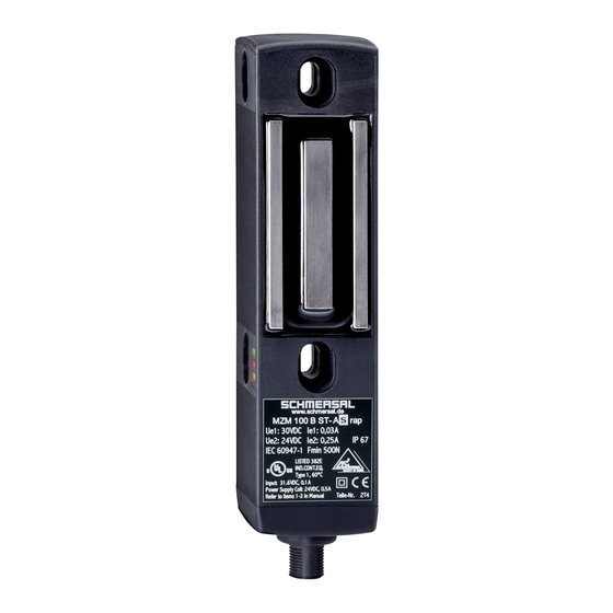
MZM 100 AS
1
Advertisement
Table of Contents

Subscribe to Our Youtube Channel
Related Manuals for schmersal MZM 100 AS


Summary of Contents for schmersal MZM 100 AS
-
Page 1: Table Of Contents
Operating instructions Electromagnetic solenoid interlock MZM 100 AS Diagnostic 6.1 LED indications ........5 6.2 Error . -
Page 2: Warning About Misuse
In case of improper use or manipulation of the safety switch- gear, personal hazards or damages to machinery or plant The latching force F of the MZM 100 AS solenoid interlock is components cannot be excluded. The relevant requirements permanently measured and checked. -
Page 3: Technical Data
≤ 2° between the solenoid interlock and the actuator. - Rated impulse withstand voltage U 0.8 kV For fitting the MZM 100 AS and the actuator, two mounting holes for M6 - Rated insulation voltage U 32 VDC screws with washers (washers included in delivery) are provided. -
Page 4: Dimensions
The control system with the AS-Interface Master can lock and unlock the solenoid interlock through the output bit 0 of the addressed AS-i slave. To lock the interlock, output bit DO 0 of the MZM 100 AS must be set to "1" by the control. -
Page 5: Status Signal "Safety Release
When the interlocking function of the solenoid interlock is blocked and • Now wait for the 10-minutes tampering protection time to no latching force of at least 500 N could be generated, the MZM 100 AS expire with the safety guard closed, until the LED’s go out will emit a warning message. -
Page 6: Diagnostic Signal Periphery Error
MZM 100 AS 6.5 Diagnostic signal periphery error 8. Disassembly and disposal All warnings or error messages of the MZM 100 AS are transmitted as "periphery error" to the control system through the AS-i master. 8.1 Disassembly The signal "periphery error" is a centralised alarm signal from warnings The safety switchgear must be disassembled in a de-energised or error messages. -
Page 7: Eu Declaration Of Conformity
Electromagnetic solenoid interlock MZM 100 AS 9. EU Declaration of conformity EU Declaration of conformity Original K.A. Schmersal GmbH & Co. KG Möddinghofe 30 42279 Wuppertal Germany Internet: www.schmersal.com We hereby certify that the hereafter described components both in their basic design and construction conform to the applicable European Directives. - Page 8 K. A. Schmersal GmbH & Co. KG Möddinghofe 30, D - 42279 Wuppertal Postfach 24 02 63, D - 42232 Wuppertal Phone: +49 - (0)2 02 - 64 74 - 0 Telefax: +49 - (0)2 02 - 64 74 - 1 00 E-Mail: info@schmersal.com...
Need help?
Do you have a question about the MZM 100 AS and is the answer not in the manual?
Questions and answers