
Subscribe to Our Youtube Channel
Related Manuals for schmersal AZM40Z-ST-1P2P


Summary of Contents for schmersal AZM40Z-ST-1P2P
-
Page 1: Table Of Contents
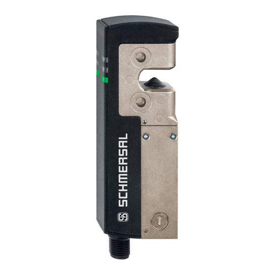
ÇALIŞTIRMA VE MONTAJ TALIMATLARI Solenoid interlock AZM40Z-ST-1P2P (Test) Table of Contents 1 About this document 1.1 Function 1.2 Target group of the operating instructions: authorised qualified personnel 1.3 Explanation of the symbols used 1.4 Appropriate use 1.5 General safety instructions 1.6 Warning about misuse... -
Page 2: Target Group Of The Operating Instructions: Authorised Qualified Personnel
The user must observe the safety instructions in this operating instructions manual, the country specific installation standards as well as all prevailing safety regulations and accident prevention rules. Further technical information can be found in the Schmersal catalogues or in the online catalogue on the Internet: products.schmersal.com. -
Page 3: Warning About Misuse
There are no residual risks, provided that the safety instructions as well as the instructions regarding mounting, commissioning, operation and maintenance are observed. 1.6 Warning about misuse In case of inadequate or improper use or manipulations of the component, personal hazards or damage to machinery or plant components cannot be excluded. -
Page 4: Special Versions
2.2 Special versions For special versions, which are not listed in the ordering code, these specifications apply accordingly, provided that they correspond to the standard version. 2.3 Purpose The non-contact, electronic safety switchgear is designed for application in safety circuits and is used for monitoring the position and locking of movable safety guards. - Page 5 Verileri TÜV cULus Genel veriler Normlar, talimatlar EN ISO 13849-1 EN ISO 14119 EN IEC 60947-5-3 EN IEC 61508 genel bilgiler Evrensel Kodlama Coding level according to EN ISO 14119 düşük Etkili kural RFID Frequency band RFID 125 kHz Transmitter output RFID, maximum -6 dB/m Gövdelerin malzemesi Light alloy die cast and plastic (glass-fibre reinforced...
- Page 6 Kontrol kategorisi PFH değeri 1,10 x 10⁻⁹ /h PFD değeri 8,90 x 10⁻⁵ Safety Integrity Level (SIL), suitable for applications in Mission time 20 Yıl(lar) Güvenlik sınıflandırması - Kilitleme fonksiyonu Performance Level, up to Kontrol kategorisi PFH değeri 3,00 x 10⁻⁹ /h PFD değeri 2,40 x 10⁻⁴...
- Page 7 Konektör, konektör Konektör M12, 8-kutup, A-kodlanmış Mekanik veriler - Boyutlar Sensörün boyu 119,5 mm Sensörün genişliği 40 mm Sensörün yüksekliği 20 mm Ortam koşulları Koruma sınıfı IP67 IP66 Ambient temperature +0 ... +55 °C Storage and transport temperature -40 ... +85 °C Göreli nem, maximum 93 % Note (Relative humidity)
- Page 8 Elektriksel nominal sigorta değeri, maximum Elektriksel veriler - Bobin kontrollu IN Designation, Magnet control Mıknatıs girişlerinin anahtarlama eşikleri -3 V … 5 V (Low) 15 V … 30 V (High) Magnet switch-on time 100 % Test pulse duration, maximum 5 ms Test pulse interval, minimum 40 ms Classification ZVEI CB24I, Sink...
- Page 9 Classification ZVEI CB24I, Source Classification ZVEI CB24I, Sink Elektriksel veriler - Diyagnostik çıkış Designation, Diagnostic outputs Design of control elements short-circuit proof, p-type Voltage drop U , maximum Voltage, Utilisation category DC-12 24 VDC Current, Utilisation category DC-12 0,05 A Voltage, Utilisation category DC-13 24 VDC Current, Utilisation category DC-13...
-
Page 10: Mounting
This device complies with the nerve stimulation limits (ISED CNR-102) when operated at a minimum distance of 100 In the event of changes or modifications that have not been expressly approved by K.A. Schmersal GmbH & Co. KG, the user's authorisation to use the device may become ineffective. - Page 11 For attachment of the solenoid interlock and the actuator, two mounting holes for M5 screws are provided. The M5 screws must be at least strength class 8.8 or, in stainless steel, strength class 80. The tightening torque of the M5 screws is 4 ...
- Page 12 Actuation direction The actuator can be continuously inserted by 180°. 12-28...
- Page 13 The actuator must be permanently fitted to the safety guards and protected against displacement by suitable measures (tamperproof screws, gluing, drilling of the screw heads). Authorised actuator and interlock offset Tilt angle Rotating angle Actuating directions and switch distances The AZM40 can be operated within the following tolerance limits: X axis - 3 mm...
-
Page 14: Manual Release
The hexagon socket screws must not be completely unscrewed. To avoid any interference inherent to this kind of system and any reduction of the switching distances, please observe the following guidelines: Metal parts and magnetic fields in the area of the solenoid interlock and the actuator can influence the switch distance or lead to malfunctions Keep away from metal chips Minimum distance between AZM40 solenoid interlocks (in mm) -
Page 15: Dimensions
For installation and maintenance, the solenoid interlock can be unlocked in a de-energised condition. The solenoid interlock is unlocked by turning the auxiliary release anti-clockwise. The normal locking function is only restored after the manual release has been returned to its original position. Do not turn the manual release beyond the end stop. - Page 16 Optional system components Retrofit kit emergency exit/emergency release The retrofit kit is used for subsequent functional expansion of the solenoid interlock. Designation Ordering code Emergency Exit ACC-AZM40-LEV-T 103053182 Emergency release ACC-AZM40-LEV-N 103054268 Emergency release with pushbutton - for 40 mm profiles ACC-AZM40-PT-T-40MM 103054271 - for 170 mm profiles...
-
Page 17: Electrical Connection
ACC-AZM40-LEV ACC-AZM40-PT Image not found or type unknown Image not found or type unknown PHO_PRO_APP_kaz40f44-sw PHO_PRO_APP_kaz40f45-sw Designation Ordering code Lockout device SZ40 103053182 Universal mounting plate, for 20, 30, 45, 50 MP-AZM40 103045324 and 60 mm profile systems, 2 pcs. Tamper-proof screws M5 x 25, flat head, 2 ACC-NRS-M5X25-FHS-2PCS 103045415... -
Page 18: Requirements For The Connected Safety-Monitoring Module
1 ms. The safety-monitoring module does not need to have a cross-wire short monitoring function, if necessary, the cross- wire short monitoring function must be disabled. Information for the selection of suitable safety-monitoring modules can be found in the Schmersal catalogues or in the online catalogue on the Internet: products.schmersal.com 4.3 Wiring configuration and connector accessories... -
Page 19: Wiring Examples
Connecting cables (PVC) with socket (female) M12, 8-pole - 8 x 0.21 mm², IP69 Cable length Ordering code 5.0 m 101210560 5.0 m, angled 101210561 10.0 m 103001389 15.0 m 103014823 Further versions in other lengths and with angled cable exit are available upon request. When using an angled connector, it is aligned parallel to the attachment surface and points to the side away from the actuator. -
Page 20: Actuator Teaching / Actuator Detection
Y1 and Y2 = Safety outputs → Safety monitoring module 5 Actuator teaching / actuator detection Solenoid interlocks with standard coding are ready to use upon delivery. Individually coded solenoid interlocks and actuators will require the following "teach-in" procedure: 1. Switch the solenoid interlock's voltage supply off and back on. 2. -
Page 21: Active Principle And Diagnostic Functions
6 Active principle and diagnostic functions 6.1 Magnet control The bistable interlock is released through operational setting of the IN signal (= 24 V). If the IN signal is not set (= 0 V), the solenoid interlock goes into locked state, so long as the correct actuator is inserted into the solenoid interlock. -
Page 22: Diagnostic Outputs
System condition No input signal at X1 and/or green yellow Safety guard open and a safety Flashes guard in the safety circuit (1 Hz) upstream is also open Safety guard closed and a Flashes Flashes safety guard in the safety (1 Hz) circuit upstream is open Safety guard locked and a... - Page 23 Sequence, locking signal is applied before the door is closed Disrupted process, door could not be locked or error 23-28...
- Page 24 Normal sequence, door was unlocked Sequence, door opened immediately after unlocking Disrupted process, door could not be unlocked 24-28...
-
Page 25: Diagnostic Information
Lock Unlock Locking time Door open Safety guard closed Safety guard not locked or fault Safety guard locked 6.5 Diagnostic information 25-28... - Page 26 Table 1: Diagnostic information of the safety switchgear System Magnet Safety outputs Diagnostic condition control Y1, Y2 output (bistable) green yellow AZM40Z AZM40B Door open 24 V Door closed, 24 V Flashes 24 V 24 V not locked Door closed, Flashes Flashes...
-
Page 27: Set-Up And Maintenance
Table 2: Error messages / flash codes red diagnostic LED Flash codes (red) Designation Autonomous Error cause switch-off after 1 flash pulse Error (warning) at output Y1 30 min Fault in output test or voltage at output Y1, although the output is disabled. -
Page 28: Disassembly And Disposal
28-28 Schmersal Turkey Otomasyon Ürünleri ve Hizmetleri Ltd. Şti., Atatürk Mah. Ataşehir Bulvarı No:5, 34758 Ataşehir Veriler ve ayrıntılar dikkatli bir şekilde kontrol edilmişlerdir. Görüntüler orijinalden farklı olabilir. Daha fazla teknik veri kılavuzda bulunabilir. Teknik değişiklikler ve hatalar olabilir.
Need help?
Do you have a question about the AZM40Z-ST-1P2P and is the answer not in the manual?
Questions and answers