
Related Manuals for schmersal AZM40B-ST-1P2P-PH


Summary of Contents for schmersal AZM40B-ST-1P2P-PH
-
Page 1: Table Of Contents
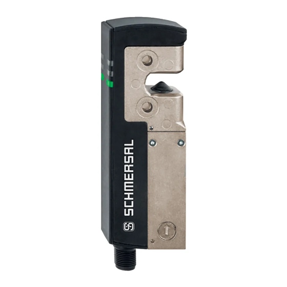
INSTRUCTIONS FOR OPERATION AND ASSEMBLY Solenoid interlock AZM40B-ST-1P2P-PH Table of Contents 1 About this document 1.1 Function 1.2 Target group of the operating instructions: authorised qualified personnel 1.3 Explanation of the symbols used 1.4 Appropriate use 1.5 General safety instructions 1.6 Warning about misuse... -
Page 2: About This Document
Warning: Failure to comply with this warning notice could lead to physical injury and/or damage to the machine. 1.4 Appropriate use The Schmersal range of products is not intended for private consumers. The products described in these operating instructions are developed to execute safety-related functions as part of an entire plant or machine. -
Page 3: Warning About Misuse
The user must observe the safety instructions in this operating instructions manual, the country specific installation standards as well as all prevailing safety regulations and accident prevention rules. Further technical information can be found in the Schmersal catalogues or in the online catalogue on the Internet: products.schmersal.com. -
Page 4: Special Versions
Individual coding Individual coding, re-teaching enabled without Counterbores for countersunk screws (standard) Flat enclosure for protruding screws Actuator AZM40-B1 AZM40-B1-PH 2.2 Special versions For special versions, which are not listed in the ordering code, these specifications apply accordingly, provided that they correspond to the standard version. -
Page 5: Technical Data
The user must evaluate and design the safety chain in accordance with the relevant standards and the required safety level. If multiple safety sensors are involved in the same safety function, the PFH values of the individual components must be added. The entire concept of the control system, in which the safety component is integrated, must be validated to the relevant standards. - Page 6 Cross-circuit detection Series-wiring Safety functions Integral system diagnostics, status Number of safety contacts Safety classification Standards EN ISO 13849-1 EN IEC 61508 Safety classification - Interlocking function Performance Level, up to Category PFH value 1.10 x 10⁻⁹ /h PFD value 8.90 x 10⁻⁵...
- Page 7 Assured switching distance "ON" S 1 mm Assured switching distance "OFF" S 8 mm Mechanical data - Connection technique Length of sensor chain, maximum 30 m Note (length of the sensor chain) Cable length and cross-section change the voltage drop dependiing on the output current Note (series-wiring) Unlimited number of devices, oberserve external line fusing, max.
- Page 8 Electrical data Operating voltage 24 VDC -15 % / +10 % (stabilised PELV power supply) No-load supply current I , typical 100 mA Current consumption magnet at switching moment, peak 600 mA / 100 ms Rated operating voltage 24 VDC Operating current 1,200 mA Required rated short-circuit current...
- Page 9 Classification ZVEI CB24I, Source Electrical data - Safety digital outputs Designation, Safety outputs Y1 and Y2 Rated operating current (safety outputs) 250 mA Design of control elements short-circuit proof, p-type Voltage drop U , maximum Leakage current I , maximum 0.5 mA Voltage, Utilisation category DC-12 24 VDC...
- Page 10 This device complies with the nerve stimulation limits (ISED CNR-102) when operated at a minimum distance of 100 In the event of changes or modifications that have not been expressly approved by K.A. Schmersal GmbH & Co. KG, the user's authorisation to use the device may become ineffective.
-
Page 11: Mounting
Este equipamento nao tem direito àprotecao contra interferência prejudicial e nao pode causar interferencia em sistemas devidamente autorizados. 20941-22-14519 Para maiores informacores consultar: www.gov.br/anatel 3 Mounting 3.1 General mounting instructions Please observe the remarks of the standards EN ISO 12100, EN ISO 14119 and EN ISO 14120. Any position is possible. - Page 12 The solenoid interlock is self-greasing. The grease on the locking bolt and in the actuator recess must not be removed. The accumulation of fine-grained dirt in the bolt area must be avoided. In that case, mounting where the bolt goes upwards from below is not advisable.
- Page 13 The actuator must be permanently fitted to the safety guards and protected against displacement by suitable measures (tamperproof screws, gluing, drilling of the screw heads). Authorised actuator and interlock offset Tilt angle Rotating angle 13-29...
- Page 14 Actuating directions and switch distances The AZM40 can be operated within the following tolerance limits: X axis - 3 mm Y axis ± 1 mm Z axis ± 1.5 mm (actuator in centre position) Adjustment The two hexagon socket screws M4 can be used to adjust the actuator tongue in the X direction, using a hexagonal key wrench AF 2 mm.
-
Page 15: Manual Release
3.2 Manual release For installation and maintenance, the solenoid interlock can be unlocked in a de-energised condition. The solenoid interlock is unlocked by turning the auxiliary release anti-clockwise. The normal locking function is only restored after the manual release has been returned to its original position. Do not turn the manual release beyond the end stop. -
Page 16: Dimensions
Connector plug M12, 8-pole LED indications Manual release (on both sides) Solenoid interlock ready for operation Solenoid interlock not ready for operation 3.3 Dimensions All measurements in mm. 16-29... - Page 17 Optional system components Retrofit kit emergency exit/emergency release The retrofit kit is used for subsequent functional expansion of the solenoid interlock. Designation Ordering code Emergency exit ACC-AZM40-LEV-T 103054265 Emergency release ACC-AZM40-LEV-N 103054268 Emergency exit with pushbutton - for 40 mm profiles ACC-AZM40-PT-T-40MM 103054271 - for profiles up to 170 mm...
-
Page 18: Electrical Connection
ACC-AZM40-LEV ACC-AZM40-PT Designation Ordering code Lockout device SZ40 103053182 Universal mounting plate, for 20, 30, 45, 50 MP-AZM40 103045324 and 60 mm profile systems, 2 pcs. Tamper-proof screws M5 x 25, flat head, 2 ACC-NRS-M5X25-FHS-2PCS 103045415 pcs. Tamper-proof screws M5 x 25, countersunk ACC-NRS-M5X25-CSS-2PCS 103045416... -
Page 19: General Information For Electrical Connection
The safety-monitoring module does not need to have a cross-wire short monitoring function, if necessary, the cross-wire short monitoring function must be disabled. Information for the selection of suitable safety-monitoring modules can be found in the Schmersal catalogues or in the online catalogue on the Internet: products.schmersal.com 4.3 Wiring configuration and connector accessories... - Page 20 Function safety Colour code of conductor Poss. Colour switchgear configuration of numbering of Schmersal code of other the connector connector plugs commercially available connector plugs With conventional diagnostic P67 / IP69 IP69 (PVC) according to EN output acc.
-
Page 21: Wiring Examples
4.4 Wiring examples The application examples shown are suggestions. They however do not release the user from carefully checking whether the switchgear and its set-up are suitable for the individual application. The application examples shown are suggestions. Wiring example: Series-wiring AZM40 The voltage is supplied at both safety inputs of the terminal safety component of the chain (considered from the safety- monitoring module). -
Page 22: Actuator Teaching / Actuator Detection
Y1 and Y2 = Safety outputs → Safety monitoring module 5 Actuator teaching / actuator detection Solenoid interlocks with standard coding are ready to use upon delivery. Individually coded solenoid interlocks and actuators will require the following "teach-in" procedure: 1. Switch the solenoid interlock's voltage supply off and back on. 2. -
Page 23: Active Principle And Diagnostic Functions
case of power failure during the lapse of time, the 10-minutes tampering protection time will restart. 6 Active principle and diagnostic functions 6.1 Magnet control The bistable interlock is released through operational setting of the IN signal (= 24 V). If the IN signal is not set (= 0 V), the solenoid interlock goes into locked state, so long as the correct actuator is inserted into the solenoid interlock. -
Page 24: Diagnostic Outputs
System condition No input signal at X1 and/or green yellow Safety guard open and a safety Flashes guard in the safety circuit (1 Hz) upstream is also open Safety guard closed and a safety Flashes Flashes guard in the safety circuit (1 Hz) upstream is open Safety guard locked and a safety... - Page 25 Sequence, locking signal is applied before the door is closed Disrupted process, door could not be locked or error Normal sequence, door was unlocked 25-29...
- Page 26 Sequence, door opened immediately after unlocking Disrupted process, door could not be unlocked Lock Unlock Locking time Door open Safety guard closed Safety guard not locked or fault Safety guard locked ...
-
Page 27: Diagnostic Information
6.5 Diagnostic information Table 1: Diagnostic information of the safety switchgear System Magnet Safety outputs Diagnostic condition control Y1, Y2 output (bistable) green yellow AZM40Z AZM40B Door open 24 V Door closed, 24 V Flashes 24 V 24 V not locked Door closed,... -
Page 28: Set-Up And Maintenance
Table 2: Error messages / flash codes red diagnostic LED Flash codes (red) Designation Autonomous Error cause switch-off after 1 flash pulse Error (warning) at output Y1 30 min Fault in output test or voltage at output Y1, although the output is disabled. -
Page 29: Disassembly And Disposal
29-29 Schmersal Canada Ltd., 29 Centennial Road, Unit 1, Orangeville, Ontario L9W 1R1 Canada The details and data referred to have been carefully checked. Images may diverge from original. Further technical data can be found in the manual. Technical amendments and errors possible.
Need help?
Do you have a question about the AZM40B-ST-1P2P-PH and is the answer not in the manual?
Questions and answers