Sign In
Upload
Manuals
Brands
schmersal Manuals
Control Unit
PSC1-C-10 Series
User Manuals: schmersal PSC1-C-10 Series Controller
Manuals and User Guides for schmersal PSC1-C-10 Series Controller. We have
5
schmersal PSC1-C-10 Series Controller manuals available for free PDF download: Installation Manual
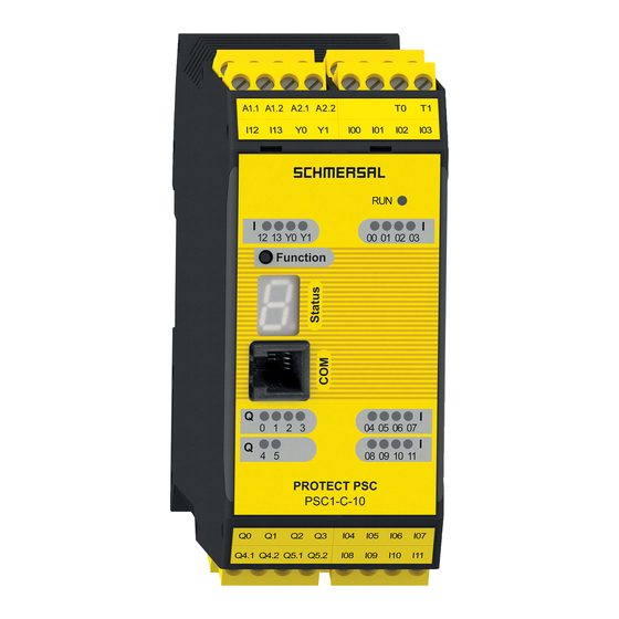
schmersal PSC1-C-10 Series Installation Manual (189 pages)
Brand:
schmersal
| Category:
Control Unit
| Size: 9 MB
Table of Contents
Table of Contents
4
Important Notes
8
Definitions
8
Reference Documents
9
Abbreviations Used
10
Safety Instructions
11
Intended Use
11
Usage in Regions with UL/CSA Requirement
12
General Safety Instructions
13
Operating and Service
14
Transport/Storage
15
Module Overview
16
Device Characteristic Data
17
Basic Modules
17
PSC1-C-10 (-Fbx
17
Tech. Characteristic Data PSC1-C-10 (-Fbx /MC)
19
PSC1-C-10-SDM1 (-Fbx /MC)
21
Tech. Characteristic Data PSC1-C-10-SDM1 (-Fbx /MC)
23
PSC1-C-10-SDM2 (-Fbx /MC)
27
Tech. Characteristic Data PSC1-C-10-SDM2 (-Fbx (1) )
27
Central Expansion Modules
29
PSC1-E-31 and PSC1-E-33
29
Tech. Characteristic Data: PSC1-E-31 and PSC1-E-33
31
Decentralised Expansion Modules (in Preparation)
33
Psc1-E-37
33
Tech. Characteristic Data: PSC1-E-37
34
Optional Universal Communication Interface
36
Tech. Characteristic Data: Optional Universal Communication Interface
37
Possible Combinations
38
Using the Memory Card
38
Encoder Specifications
39
Derating Outputs
39
Marking
40
Type Plate
40
Items Supplied
41
Safety-Related Features
42
General Layout, Safety-Related Architecture and Characteristic Data
42
Safety-Related Characteristic Data and Circuitry for Sensors Connected
44
Digital Sensors
44
Characteristics of the Sensors / Input Elements
44
DC Digital Sensors/Inputs
45
Classification of the Safe Digital Inputs
49
Connection Examples, Digital Sensors/Safety Switch
51
Overview of Achievable PL for Digital Safety Inputs
56
Sensors for Speed And/Or Position Acquisition
58
General Safety-Related Layout of Sensor Interface for Position And/Or Speed
58
General Diagnostic Measures for Encoder Interface
59
Encoder Types and Their Combinations, Diagnostic Characteristic Data
60
Specific Diagnostic Measures in Relation to the Encoder Type Used
66
Safety-Related Shutdown Thresholds, Encoder Systems for Position and Speed Acquisition
67
Safety-Related Assessment of the Encoder Types and Their Combination
71
Safety-Related Characteristic Data and Circuitry for the Outputs
73
Characteristics of the Output Elements
73
Diagnostics in the Shutdown Circuit
75
Diagnostic Functions
75
Overview of DC in Relation to Selected Diagnostic Functions
76
Permissible Capacitive and Inductive Load on Safe Outputs
77
Digital Outputs
78
Example Circuits, Basic Outputs
80
Digital Outputs I/O (Iqqx)
87
Classification of the I/O (Iqqx) on Usage as an Output
87
Example Circuits for Safe Digital Outputs I/O (Iqqx)
88
Overview of Achievable PL for Digital Safety Outputs
94
Connection and Installation
96
General Installation Instructions
96
Installation and Mounting PSC1 Module
97
Mounting Backplane Bus
97
Arrangement Examples
98
Psc1-C-10-Sdm1 + Psc1-E-31
98
Psc1-C-10-Sdm2 + Psc1-E-33
98
Mounting the Modules
99
Mounting on C Rail
99
Mounting on Backplane Bus
100
Installation and Configuration of Master Master (SMMC) and Master Slave (SDDC)
101
Schematic Diagram of the Network Topology
102
Installation of I/O Expansion
103
Physical Address Configuration for the Slave Modules (Central / Decentral)
103
Terminal Assignment
104
Terminal Assignment PSC1-C-10 (-Fbx/-MC)
105
Terminal Assignment PSC1-C-10-SDM1 (-Fbx/-MC)
107
Terminal Assignment PSC1-C-10-SDM2 (-Fbx/-MC)
109
Terminal Assignment PSC1-E-31
111
Terminal Assignment PSC1-E-33
112
Terminal Assignment PSC1-E-37 in Preparation
114
Terminal Assignment PSC1-C-10(-Sdmx)-Fbx
115
External 24 VDC Power Supply
116
Connection of the External Encoder Supply
118
Incremental, HTL (on Request), SIN/COS, SSI
118
Connection of the Digital Inputs
120
Connection of Position and Speed Sensors
121
General Instructions
121
Encoder Interface Assignment
123
Connection Variants
124
Connection of an Absolute Encoder as Master
124
Connection of an Absolute Encoder as Slave
125
Connection of an Incremental Encoder with TTL Signal Level
126
Connection of a SIN/COS Encoder
127
Connection of Proximity Switch PSC1-C-10-SDM1/2
128
Configuration of the Measurement Sections
129
General Description of the Encoder Configuration
129
Sensor Type
129
Absolute Encoder
129
Incremental Encoder
131
Sinecosine Encoder - Standard Mode
131
Proximity Switches
131
Extended Monitoring with 2 Proximity Switches
132
Response Times of the Psc1
133
Response Times in Standard Operation
134
Response Times for FAST_CHANNEL
135
Response Times for Overspeed Distance Monitoring
135
Response Times When Using the PSC1-E-3X
137
Commissioning
139
Procedure
139
Sequences for Switching on
139
Reset Behaviour
140
Reset Types and Triggering Element
141
Reset Timing
142
Reset Function
142
Example Reset Function with Protection against Incorrect Usage
144
LED Indication
147
Parameter Configuration
148
Function Test
148
Validation
148
Safety-Related Check
149
Maintenance
150
Modification / Dealing with Changes to the Device
150
Replacement of a Module
150
Servicing Interval
150
Technical Data
151
Ambient Conditions
151
Safety-Related Characteristic Data
151
Switch Types
152
Notes for Designing, Programming, Validating and Testing Safety-Related Applications
158
Risk Assessment
158
Technical Documentation Required
160
Steps Required for Designing, Realisation and Testing
161
Phases of the V Model
162
Specification of the Safety Requirements (Breakdown)
163
Specification of the Functional Safety System
166
Definition of the Safety Functions
166
Performance Level Required (Plr) (Additional Emergency Stop)
166
Example - Specification of the Safety Functions in Tabular Form
167
Software Specification
168
Hardware Specification
170
Selection of SRP/CS and Equipment
170
Examples for Hardware Specification
171
Consideration of Systematic Failures
172
Hardware and Software Design
174
Check on the Hardware Design
174
Iterative Check on the Safety Level Achieved
174
Verification of Software (Program) and Parameters
178
FUP Check
178
Validating FUP against IL and Parameters Using Validation Report
181
Performance of System Tests / FIT Test (Fault Injection Test)
183
Advertisement
schmersal PSC1-C-10 Series Installation Manual (174 pages)
Brand:
schmersal
| Category:
Industrial Equipment
| Size: 3 MB
Table of Contents
Table of Contents
4
Important Notes
7
Definitions
7
Reference Documents
8
Abbreviations Used
9
Safety Instructions
11
Intended Use
11
Usage in Regions with UL/CSA Requirement
11
General Safety Instructions
12
Operating and Service
13
Transport/Storage
13
Device Types
14
Type Code
15
Module Overview
16
Device Characteristic Data
17
Basic Modules
17
PSC1-C-10 (-Fbx (1) /-MC)
17
Tech. Characteristic Data PSC1-C-10 (-Fbx (1) /MC)
19
Psc1-C-10-Sdm1
21
Tech. Characteristic Data PSC1-C-10-SDM1 (-Fbx /MC)
23
Psc1-C-10-Sdm2
25
Tech. Characteristic Data PSC1-C-10-SDM2 (-Fbx )
27
Central Expansion Modules
29
PSC1-E-31 and PSC1-E-33
29
Optional Universal Communication Interface
32
Tech. Characteristic Data: Optional Universal Communication Interface
33
Encoder Specifications
34
Derating Outputs
34
Marking
35
Type Plate
35
Items Supplied
36
Safety-Related Features
37
General Layout, Safety-Related Architecture and Characteristic Data
37
Safety-Related Characteristic Data and Circuitry for Sensors Connected
39
Digital Sensors
39
Characteristics of the Sensors / Input Elements
39
DC Digital Sensors/Inputs
40
Classification of the Safe Digital Inputs
44
Connection Examples, Digital Sensors/Safety Switch
46
Overview of Achievable PL for Digital Safety Inputs
51
Sensors for Speed And/Or Position Acquisition
53
General Safety-Related Layout of Sensor Interface for Position And/Or Speed
53
General Diagnostic Measures for Encoder Interface
54
Encoder Types and Their Combinations, Diagnostic Characteristic Data
55
Specific Diagnostic Measures in Relation to the Encoder Type Used
57
Safety-Related Shutdown Thresholds, Encoder Systems for Position and Speed Acquisition
58
Safety-Related Assessment of the Encoder Types and Their Combination
61
Safety-Related Characteristic Data and Circuitry for the Outputs
63
Characteristics of the Output Elements
63
Diagnostics in the Shutdown Circuit
65
Diagnostic Functions
65
Overview of DC in Relation to Selected Diagnostic Functions
66
Permissible Capacitive and Inductive Load on Safe Outputs
67
Digital Outputs
68
Characteristic Data of the Basic Outputs
68
Example Circuits, Basic Outputs
70
Digital Outputs I/O (Iqqx)
78
Classification of the I/O (Iqqx) on Usage as an Output
78
Example Circuits for Safe Digital Outputs I/O (Iqqx)
79
Overview of Achievable PL for Digital Safety Outputs
84
Connection and Installation
86
General Installation Instructions
86
Installation and Mounting PSC1 Module
88
Mounting Backplane Bus
88
Arrangement Examples
89
Psc1-C-10-Sdm1 + Psc1-E-31
89
Psc1-C-10-Sdm2 + Psc1-E-33
89
Mounting the Modules
90
Mounting on C Rail
90
Mounting on Backplane Bus
91
Installation of I/O Expansion
92
Physical Address Configuration for the Slave Modules
92
Installation and Configuration of Master Master (SMMC) and Master Slave (SDDC)
93
SMMC/SDDC Topology Rules
94
Exemplary Schematic Diagram of a Network Topology
95
Terminal Assignment
96
Terminal Assignment PSC1-C-10 (-Fbx/-MC)
97
Terminal Assignment PSC1-C-10-SDM1 (-Fbx/-MC)
98
Terminal Assignment PSC1-C-10-SDM2 (-Fbx/-MC)
99
Terminal Assignment PSC1-E-31
101
Terminal Assignment PSC1-E-33
102
External 24 VDC Power Supply
104
Connection of the External Encoder Supply
106
Incremental, SIN/COS, SSI
106
Connection of the Digital Inputs
107
Connection of Position and Speed Sensors
108
General Instructions
108
Encoder Interface Assignment
110
Connection Variants
111
Connection of an Absolute Encoder as Master
111
Connection of an Absolute Encoder as Slave
112
Connection of an Incremental Encoder with TTL Signal Level
113
Connection of a SIN/COS Encoder
114
Connection of Proximity Switch (PSC1-C-10-SDM1/2 Only)
115
Configuration of the Measurement Sections
116
General Description of the Encoder Configuration
116
Sensor Type
116
Absolute Encoder
116
Incremental Encoder
118
Sincos Encoder - Standard Mode
118
Proximity Switches
118
Extended Monitoring with 2 Proximity Switches
119
Response Times of the Psc1
120
Response Times in Standard Operation
121
Response Times for FAST_CHANNEL
122
Response Times for Overspeed Distance Monitoring
123
Response Times When Using the PSC1-E-3X
125
Commissioning
127
Procedure
127
Sequences for Switching on
127
Reset Behaviour
128
Reset Types and Triggering Element
128
Reset Timing
129
Reset Function
129
Example Reset Function with Protection against Incorrect Usage
131
LED Indication
134
Parameter Configuration
135
Using the Memory Card
135
Function Test
136
Validation
136
Safety-Related Check
137
Maintenance
138
Modification / Dealing with Changes to the Device
138
Replacement of a Module
138
Servicing Interval
138
Technical Data
139
Ambient Conditions
139
Safety-Related Characteristic Data
139
Switch Types
140
Notes for Designing, Programming, Validating and Testing Safety-Related Applications
147
Risk Assessment
147
Technical Documentation Required
149
Steps Required for Designing, Realisation and Testing
150
Phases of the V Model
151
Specification of the Safety Requirements (Breakdown)
152
Specification of the Functional Safety System
155
Definition of the Safety Functions
155
Performance Level Required (Plr) (Additional Emergency Stop)
155
Example - Specification of the Safety Functions in Tabular Form
156
Software Specification
157
Hardware Specification
159
Selection of SRP/CS and Equipment
159
Examples for Hardware Specification
160
Consideration of Systematic Failures
161
Hardware and Software Design
162
Check on the Hardware Design
162
Iterative Check on the Safety Level Achieved
163
Verification of Software (Program) and Parameters
165
FUP Check
165
Validating FUP against IL and Parameters Using Validation Report
167
Performance of System Tests / FIT Test (Fault Injection Test)
170
Appendix
171
Appendix A - Categorisation of the Switch Types
171
PSC1-C-10 Installation Manual V2.7
174
CE - Declaration of Conformity
174
schmersal PSC1-C-10 Series Installation Manual (173 pages)
Brand:
schmersal
| Category:
Control Unit
| Size: 3 MB
Table of Contents
Table of Contents
4
Important Notes
7
Definitions
7
Reference Documents
8
Abbreviations Used
9
Safety Instructions
11
Intended Use
11
Usage in Regions with UL/CSA Requirement
11
General Safety Instructions
12
Operating and Service
13
Transport/Storage
13
Device Types
14
Module Overview
15
Device Characteristic Data
16
Basic Modules
16
PSC1-C-10 (-Fbx (1) /-MC)
16
Tech. Characteristic Data PSC1-C-10 (-Fbx (1) /MC)
18
Psc1-C-10-Sdm1
20
Tech. Characteristic Data PSC1-C-10-SDM1 (-Fbx /MC)
22
Psc1-C-10-Sdm2
24
Tech. Characteristic Data PSC1-C-10-SDM2 (-Fbx )
26
Central Expansion Modules
28
PSC1-E-31 and PSC1-E-33
28
Optional Universal Communication Interface
31
Tech. Characteristic Data: Optional Universal Communication Interface
32
Possible Combinations
32
Encoder Specifications
33
Derating Outputs
33
Marking
34
Type Plate
34
Items Supplied
35
Safety-Related Features
36
General Layout, Safety-Related Architecture and Characteristic Data
36
Safety-Related Characteristic Data and Circuitry for Sensors Connected
38
Digital Sensors
38
Characteristics of the Sensors / Input Elements
38
DC Digital Sensors/Inputs
39
Classification of the Safe Digital Inputs
43
Connection Examples, Digital Sensors/Safety Switch
45
Overview of Achievable PL for Digital Safety Inputs
50
Sensors for Speed And/Or Position Acquisition
52
General Safety-Related Layout of Sensor Interface for Position And/Or Speed
52
General Diagnostic Measures for Encoder Interface
53
Encoder Types and Their Combinations, Diagnostic Characteristic Data
54
Specific Diagnostic Measures in Relation to the Encoder Type Used
56
Safety-Related Shutdown Thresholds, Encoder Systems for Position and Speed Acquisition
57
Safety-Related Assessment of the Encoder Types and Their Combination
60
Safety-Related Characteristic Data and Circuitry for the Outputs
62
Characteristics of the Output Elements
62
Diagnostics in the Shutdown Circuit
64
Diagnostic Functions
64
Overview of DC in Relation to Selected Diagnostic Functions
65
Permissible Capacitive and Inductive Load on Safe Outputs
66
Digital Outputs
67
Characteristic Data of the Basic Outputs
67
Example Circuits, Basic Outputs
69
Digital Outputs I/O (Iqqx)
76
Classification of the I/O (Iqqx) on Usage as an Output
76
Example Circuits for Safe Digital Outputs I/O (Iqqx)
77
Overview of Achievable PL for Digital Safety Outputs
82
Connection and Installation
84
General Installation Instructions
84
Installation and Mounting PSC1 Module
86
Mounting Backplane Bus
86
Arrangement Examples
87
Psc1-C-10-Sdm1 + Psc1-E-31
87
Psc1-C-10-Sdm2 + Psc1-E-33
87
Mounting the Modules
88
Mounting on C Rail
88
Mounting on Backplane Bus
89
Installation of I/O Expansion
90
Physical Address Configuration for the Slave Modules
90
Installation and Configuration of Master Master (SMMC) and Master Slave (SDDC)
91
SMMC/SDDC Topology Rules
92
Exemplary Schematic Diagram of a Network Topology
93
Terminal Assignment
94
Terminal Assignment PSC1-C-10 (-Fbx/-MC)
95
Terminal Assignment PSC1-C-10-SDM1 (-Fbx/-MC)
96
Terminal Assignment PSC1-C-10-SDM2 (-Fbx/-MC)
97
Terminal Assignment PSC1-E-31
100
Terminal Assignment PSC1-E-33
101
External 24 VDC Power Supply
103
Connection of the External Encoder Supply
105
Incremental, SIN/COS, SSI
105
Connection of the Digital Inputs
106
Connection of Position and Speed Sensors
107
General Instructions
107
Encoder Interface Assignment
109
Connection Variants
110
Connection of an Absolute Encoder as Master
110
Connection of an Absolute Encoder as Slave
111
Connection of an Incremental Encoder with TTL Signal Level
112
Connection of a SIN/COS Encoder
113
Connection of Proximity Switch (PSC1-C-10-SDM1/2 Only)
114
Configuration of the Measurement Sections
115
General Description of the Encoder Configuration
115
Sensor Type
115
Absolute Encoder
115
Incremental Encoder
117
Sincos Encoder - Standard Mode
117
Proximity Switches
117
Extended Monitoring with 2 Proximity Switches
118
Response Times of the Psc1
119
Response Times in Standard Operation
120
Response Times for FAST_CHANNEL
121
Response Times for Overspeed Distance Monitoring
122
Response Times When Using the PSC1-E-3X
124
Commissioning
126
Procedure
126
Sequences for Switching on
126
Reset Behaviour
127
Reset Types and Triggering Element
127
Reset Timing
128
Reset Function
128
Example Reset Function with Protection against Incorrect Usage
130
LED Indication
133
Installation Manual
133
Parameter Configuration
134
Using the Memory Card
134
Function Test
135
Validation
135
Safety-Related Check
136
Maintenance
137
Modification / Dealing with Changes to the Device
137
Replacement of a Module
137
Servicing Interval
137
Technical Data
138
Ambient Conditions
138
Safety-Related Characteristic Data
138
Switch Types
139
Notes for Designing, Programming, Validating and Testing Safety-Related Applications
146
Risk Assessment
146
Technical Documentation Required
148
Steps Required for Designing, Realisation and Testing
149
Phases of the V Model
150
Specification of the Safety Requirements (Breakdown)
151
Specification of the Functional Safety System
154
Definition of the Safety Functions
154
Performance Level Required (Plr) (Additional Emergency Stop)
154
Example - Specification of the Safety Functions in Tabular Form
155
Software Specification
156
Hardware Specification
158
Selection of SRP/CS and Equipment
158
Examples for Hardware Specification
159
Consideration of Systematic Failures
160
Hardware and Software Design
161
Check on the Hardware Design
161
Iterative Check on the Safety Level Achieved
162
Verification of Software (Program) and Parameters
164
FUP Check
164
Validating FUP against IL and Parameters Using Validation Report
166
Performance of System Tests / FIT Test (Fault Injection Test)
169
Appendix
170
Appendix A - Categorisation of the Switch Types
170
PSC1-C-10 Installation Manual V2.6
173
CE - Declaration of Conformity
173
Advertisement
schmersal PSC1-C-10 Series Installation Manual (177 pages)
Brand:
schmersal
| Category:
Industrial Equipment
| Size: 5 MB
Table of Contents
Table of Contents
4
Important Notes
7
Definitions
7
Reference Documents
8
Abbreviations Used
9
Safety Instructions
11
Intended Use
11
Usage in Regions with UL/CSA Requirement
11
General Safety Instructions
12
Operating and Service
13
Transport/Storage
13
Device Types
14
Module Overview
16
Device Characteristic Data
17
Basic Modules
17
PSC1-C-10 (-Fbx (1) )
19
PSC1-C-10-SDM1 (-Fbx )
20
PSC1-C-10-SDM2 (-Fbx )
24
Central Expansion Modules
27
PSC1-E-31 and PSC1-E-33
27
Decentral Expansion Modules
30
Psc1-E-37
30
Optional Universal Communication Interface
32
Possible Combinations
34
Using the Memory Card
34
Encoder Specifications
36
Marking
37
Type Plate
37
Items Supplied
38
Safety-Related Features
39
General Layout, Safety-Related Architecture and Characteristic Data
39
Safety-Related Characteristic Data and Circuitry for Sensors Connected
40
Digital Sensors
41
Characteristics of the Sensors / Input Elements
41
DC Digital Sensors/Inputs
41
Classification of the Safe Digital Inputs
45
Connection Examples, Digital Sensors
47
Overview of Achievable PL for Digital Safety Inputs
52
Sensors for Speed And/Or Position Acquisition
54
General Safety-Related Layout of Sensor Interface for Position And/Or Speed
54
General Diagnostic Measures for Encoder Interface
55
Encoder Types and Their Combinations, Diagnostic Characteristic Data
56
Specific Diagnostic Measures in Relation to the Encoder Type Used
60
Safety-Related Shutdown Thresholds, Encoder Systems for Position and Speed Acquisition
61
Safety-Related Assessment of the Encoder Types and Their Combination
64
Safety-Related Characteristic Data and Circuitry for the Outputs
66
Characteristics of the Output Elements
66
Diagnostics in the Shutdown Circuit
67
Diagnostic Functions
67
Overview of DC in Relation to Selected Diagnostic Functions
68
Permissible Capacitive and Inductive Load on Safe Outputs
69
Digital Outputs
69
Example Circuits, Basic Outputs
72
Digital Outputs I/O (Iqqx)
79
Classification of the I/O (Iqqx) on Usage as an Output
79
Example Circuits for Safe Digital Outputs I/O (Iqqx)
80
Overview of Achievable PL for Digital Safety Outputs
85
Connection and Installation
87
General Installation Instructions
87
Installation and Mounting PSC1 Module
88
Mounting Backplane Bus
88
Arrangement Examples
89
PSC1-C-10-SDM1 + PSC1-C-10-SDM1 + PSC1-C-10-SDM1-Fbx
89
PSC1-C-10-SDM2 PSC1-C-10-SDM1-Fbx
89
Mounting the Modules
90
Mounting on C Rail
90
Mounting on Backplane Bus
91
Installation and Configuration of Master <-> Master (SMMC) and Master <-> Slave (SDDC)
92
Network Topology
93
Installation of I/O Expansion
94
Physical Address Configuration for the Slave Modules (Central / Decentral)
94
Terminal Assignment
95
Terminal Assignment PSC1-C-10
95
Terminal Assignment PSC1-C-10-SDM1
96
Terminal Assignment PSC1-C-10-SDM2
97
Terminal Assignment PSC1-E-31
99
Terminal Assignment PSC1-E-33
100
Terminal Assignment PSC1-E-37
102
Terminal Assignment PSC1-C-10-X-Fbx
104
External 24 VDC Power Supply
105
Connection of the External Encoder Supply
107
Incremental, HTL, SIN/COS, SSI
107
Connection of the Digital Inputs
108
Connection of Position and Speed Sensors
109
General Instructions
109
Encoder Interface Assignment
111
Connection Variants
112
Connection of an Absolute Encoder as Master
112
Connection of an Absolute Encoder as Slave
113
Connection of an Incremental Encoder with TTL Signal Level
114
Connection of a SIN/COS Encoder
115
Connection of Proximity Switch PSC1-C-10-SDM1/2
117
Configuration of the Measurement Sections
118
General Description of the Encoder Configuration
118
Sensor Type
118
Absolute Encoder
118
Incremental Encoder
120
Sincos Encoder - Standard Mode
120
Proximity Switch
120
Expanded Monitoring, Proximity Switch / Proximity Switch
121
Response Times of the Psc1
122
Response Times in Standard Operation
122
Response Time for FAST_CHANNEL
124
Response Time for Overspeed Distance Monitoring
124
Response Times on Usage of the PSC1-E-3X
126
Commissioning
128
Procedure
128
Sequences for Switching on
128
Reset Behaviour
129
Reset Types and Triggering Element
129
Reset Timing
130
Reset Function
130
Example Reset Function with Protection against Incorrect Usage
132
LED Indication
135
Parameter Configuration
136
Function Check
136
Validation
136
Safety-Related Check
137
Servicing
138
Modification / Dealing with Changes to the Device
138
Replacement of a Module
138
Servicing Interval
138
Technical Data
139
Ambient Conditions
139
Safety-Related Characteristic Data
139
Switch Types
140
Notes for Designing, Programming, Validating and Testing Safety-Related Applications
147
Risk Assessment
147
Technical Documentation Required
149
Steps Required for Designing, Realisation and Testing
150
Phases of the V Model
151
Specification of the Safety Requirements (Breakdown)
152
Specification of the Functional Safety System
155
Definition of the Safety Functions
155
Performance Level Required (Plr) (Additional Emergency Stop)
155
Example - Specification of the Safety Functions in Tabular Form
156
Software Specification
157
Hardware Specification
159
Selection of SRP/CS and Equipment
159
Examples for Hardware Specification
160
Consideration of Systematic Failures
161
Hardware and Software Design
162
Checking the Hardware Design
162
Iterative Check on the Safety Level Achieved
162
Verification of Software (Program) and Parameters
166
FUP Check
166
Validating FUP against IL and Parameters Using Validation Report
168
Undertaking the System Test / FIT (Fault Injection Test)
171
Appendix
172
Appendix A - Categorisation of the Switch Types
172
schmersal PSC1-C-10 Series Installation Manual (166 pages)
field buses
Brand:
schmersal
| Category:
Controller
| Size: 6 MB
Table of Contents
Table of Contents
3
1 Important Notes
7
Definitions
7
Other Applicable Documents
7
Table 1: Other Applicable Documents
7
Abbreviations Used
8
Table 2: Abbreviations
8
2 Safety Instructions
9
Intended Use
9
General Safety Instructions
9
Operating and Service
10
Transport/Storage
10
3 Device Description and Function
11
Fieldbus-Specific Properties
12
Ethernet/Ip
12
Table 3: Fieldbus-Specific Properties Ethernet/Ip
12
Profinet Io
13
Ethercat
13
Table 4: Fieldbus-Specific Properties PROFINET
13
Table 5: Fieldbus-Specific Properties Ethercat
13
Profibus
14
Table 6: Fieldbus-Specific Properties PROFIBUS
14
Canopen
15
Table 7: Fieldbus-Specific Properties Canopen
15
4 Equipment and Settings
16
Ethernet-Based Device Variants (-FB1)
16
Figure 1: Front View Device Variant (-FB1); here PSC1-C-10-FB1
16
CAN or RS485-Based Device Variants (-FB2)
17
Figure 2: Front View Device Variant (-FB2); here PSC1-C-10-FB2
17
Diagnostic Leds
18
Figure 3: Diagnostic Leds
18
Table 8: Diagnostic Leds Display Functions
19
5 Connection and Installation
20
General Installation Instructions
20
Figure 4: Example for Fieldbus Connection to the FB2.1 / FB2.2 (Ethernet/Ip) Sockets
20
Installing PSC1 Modules
21
Assembly of Modules and Backplane Bus
22
Address Selector Switch
22
Figure 5: Assembly
22
Figure 6: Address Selector Switch for PSC1 Devices with Option FB2
22
Assignment of Connection Socket
23
Fieldbus Interface Connection Socket with the FB1 Option (RJ45 Socket)
23
Fieldbus Interface Connection Socket with the FB2 Option (D-SUB- Socket)
23
6 Modification / Dealing with Changes to the Device
23
Figure 7: Fieldbus Interface Connection Socket / FB1 Option (RJ45 Socket)
23
Figure 8: Fieldbus Interface Connection Socket / FB2 Option (D-SUB)
23
7 Maintenance
24
Replacement of a Module
24
8 Technical Data
24
Ambient Conditions
24
Table 8: Ambient Conditions
24
9 Diagnostic Data
25
PSC1-C-10-X-FB1/2 Diagnostic Data
25
Table 9: PSC1-C-10-X-FB1/2 Logic Data
25
Table 10: PSC1-C-10-X-FB1/2 Process Data
25
PSC1-C-100-X-FB1/2 Diagnostic Data
26
Structure for Device Profile 0 (= Free Assignment)
26
Configuration with Axis Extension Modules (Slave Module)
26
Table 11: Structure for Device Profile 0 (= Free Assignment) with Extension Modules
26
Table 13: Bit Data Type "1
26
Configuration Without Axis Extension Modules (Slave Module)
27
Table 12: Structure for Device Profile 0 (= Free Assignment) Without Extension Modules
27
Table 14: Bit Data Type "2
27
Data Types
28
Table 15: Process Data
29
Structure for Device Profile 1 (= Only Logic Data)
30
Table 16: Structure for Device Profile 1 (= Only Logic Data)
30
Structure for Device Profile 2 (= Logic Data + Process Data for each Slave)
31
Table 17: Structure for Device Profile 1 (= Logic Data + Process Data for each Slave)
33
SD-Bus Data
34
Fieldbus Data SD-Bus Gateway
34
Fieldbus Data SD Slave
34
Diagnostic Byte Gateway
34
Structure of the SD Bytes in the Fieldbus Protocol
35
Reading Acyclic Data from the SD Slave
36
Table 18: Overview of the Instructions and Response Data
37
10 Assigning Ip Address (-Fb1 Option Only)
39
11 Commissioning and Configuration Profinet in Safeplc2 and Tia Portal (from Step 7 V10)
41
Figure 9: Properties PSC1 Basic Device - PROFINET
41
Figure 10: Properties Fieldbus (Fieldbus PROFINET) - Non-Safe
42
Figure 11: Properties Fieldbus (Fieldbus PROFINET) - Safe
42
Figure 12: Properties Fieldbus (Fieldbus PROFINET) - both
43
Parameter Configuration
46
Installing the XML File
46
Create Project and Insert PSC1 with PROFINET
48
Setting up Secure Data Transmission
52
Setting up an Online Connection
55
Examples of Non-Secure Data Transmission
61
Examples of Secure Data Transmission
64
12 Commissioning and Configuration Ethernet/Ip in Safeplc2 and Rslogix500
66
Figure 13: Properties PSC1 Basic Device - Ethernet/Ip
66
Figure 14: Properties Fieldbus (Fieldbus Ethernet/Ip) - Non-Safe
67
Parameter Configuration
70
Create Project
70
Installing the EDS File
73
Insert PSC1
77
Setting up an Online Connection
81
Examples of Non-Secure Data Transmission
84
Assigning IP Addresses with the BOOTP-DHCP Tool
86
Assigning IP Addresses Using the IP Administrator
89
13 Commissioning and Configuration Ethercat in Safeplc2 and Twincat 3
91
Figure 15: Properties PSC1 Basic Device - Ethercat
91
Figure 16: Properties Fieldbus (Fieldbus Ethercat) - Non-Safe
92
Parameter Configuration
96
Create Project and Search for Target System
96
Find Connected I/O Devices
99
Examples of Non-Secure Data Transmission
104
Create Safety Project
109
14 Commissioning and Configuration Proifbus in Safeplc2 and Tia Portal (from Step 7 V10)
132
Figure 17: Properties PSC1 Basic Device - PROFIBUS
132
Figure 18: Properties Fieldbus (Fieldbus PROFIBUS) - Non-Safe
133
Figure 19: Properties Fieldbus (Fieldbus PROFIBUS) - Safe
133
Figure 20: Properties Fieldbus (Fieldbus PROFIBUS) - both
134
Parameter Configuration
137
Create Project and Insert PSC1 with PROFIBUS
140
Setting up Secure Data Transmission
145
Setting up Non-Secure Data Transmission
147
Setting up an Online Connection
149
Examples of Non-Secure Data Transmission
153
Examples of Secure Data Transmission
156
Examples of Secure Data Transmission
157
15 Commissioning and Configuration Canopen
159
Integrating the Device Description File
161
Creating a New Project
162
Advertisement
Related Products
schmersal PSC1-C-100 Series
schmersal PSC1-C-100-FB Series
schmersal PSC1-C-100-MC
schmersal PSC1-C-100-FB1
schmersal PSC1-C-10-SDM Series
schmersal PSC1-C-10-MC
schmersal PSC1-C-10-FBx
schmersal PSC1-C-10-SDM1
schmersal PSC1-C-10-SDM1-MC
schmersal PSC1-C-10-SDM1-FBx
schmersal Categories
Industrial Equipment
Switch
Security Sensors
Control Unit
Locks
More schmersal Manuals
Login
Sign In
OR
Sign in with Facebook
Sign in with Google
Upload manual
Upload from disk
Upload from URL