schmersal PSC1 Installation Manual
Field buses
Hide thumbs
Also See for PSC1:
- Installation manual (201 pages) ,
- Installation manual (177 pages) ,
- Installation manual (174 pages)

Subscribe to Our Youtube Channel
Related Manuals for schmersal PSC1


Summary of Contents for schmersal PSC1
- Page 1 Installation manual PSC1 field buses EtherNet/IP PROFINET IO EtherCAT PROFIBUS CANopen...
- Page 2 Installation manual Installation manual for PSC1 field buses: EtherNet/IP, PROFINET IO, EtherCAT, PROFIBUS und CANopen Note: The German version is the original version of the installation instructions. As of: 09/2019 Subject to technical change without notice. The content of our documentation has been prepared with the greatest possible care and corresponds to the latest information available to us.
-
Page 3: Table Of Contents
CAN or RS485-based device variants (-FB2) ..................17 Diagnostic LEDs..........................18 CONNECTION AND INSTALLATION ............... 20 General installation instructions ......................20 Installing PSC1 modules ........................21 Assembly of modules and backplane bus ..................22 Address selector switch ........................22 Assignment of connection socket ...................... 23 5.5.1... - Page 4 Installation manual 11.1.1 Installing the XML file .....................46 11.1.2 Create project and insert PSC1 with PROFINET ............48 11.1.3 Setting up secure data transmission ................52 11.1.4 Setting up an online connection ..................55 11.1.5 Examples of non-secure data transmission ..............61 11.1.6 Examples of secure data transmission ................64 COMMISSIONING AND CONFIGURATION ETHERNET/IP IN SAFEPLC2 AND RSLOGIX500 ....................
- Page 5 Figure 4: Example for fieldbus connection to the FB2.1 / FB2.2 (EtherNet/IP) sockets ..20 Figure 5: Assembly ......................22 Figure 6: Address selector switch for PSC1 devices with option FB2 ........22 Figure 7: Fieldbus interface connection socket / FB1 option (RJ45 socket) ......23 Figure 8: Fieldbus interface connection socket / FB2 option (D-SUB) ........
- Page 6 Project planning examples added (Sections 10 - 13) V 1.5 06/04/2018 Editorial changes V 2.0 04/05/2018 Chapter 9.3 SD-Bus data added V 2.1 18/07/2018 CANopen added V 2.2 16/09/2019 Commissioning CANopen added, Description IP-Administrator added Installation manual PSC1-Field buses V2.2.docx Page 6 of 166...
-
Page 7: Important Notes
Technicians and engineers 1.1 Definitions The term PSC1 is used as the generic term for all derivatives of the PSC1 product line. If reference is made to a specific derivative in the description, the complete identifier is used. COM is the abbreviation for the universal communication interface of the PSC1. -
Page 8: Abbreviations Used
Programmable Logic Controller Power on Reset SDDC Safe Device To Device Communication SELV Safety Extra Low Voltage Synchronous Serial Interface Verband der Elektrotechnik, Elektronik und Informationstechnik e. V. Table 2: Abbreviations Installation manual PSC1-Field buses V2.2.docx Page 8 of 166... -
Page 9: Safety Instructions
Installation manual 2 Safety instructions 2.1 Intended use The universal communication interface COM is an extension for the modules PSC1-C-10-x- FB1, PSC1-C-10-x-FB2, PSC1-C-100-FB1, PSC1-C-100-FB2 and their variants for non-safe data transmission via an Ethernet, or CAN or RS485 based protocol. -
Page 10: Operating And Service
This usage will also render void any claim under the warranty or any claim for claim damages against K.A. Schmersal GmbH & Co. KG. 2.3 Operating and service Prior to installing and removing the module, or disconnecting the signal wires, the module is to be electrically isolated. -
Page 11: Device Description And Function
(PSC1-C-10-x-FBx) or connected to it via the backplane bus (PSC1-C-100-FBx). In addition, up to 32 non-safe functional inputs are available on the PSC1, via which digital information can be received from the higher-level standard controller. -
Page 12: Fieldbus-Specific Properties
3.1 Fieldbus-specific properties 3.1.1 EtherNet/IP Response time Processing time for incoming fieldbus protocols: min.1 ms; Response time depends on the PSC1 system: see installation manual PSC1 Maximum number of output 68 bytes (1) data (O → T) Maximum number of input 192 bytes (2) data (T →... -
Page 13: Profinet Io
Installation manual 3.1.2 PROFINET IO Response time Processing time for incoming fieldbus protocols: min.1 Response time depends on the PSC1 system: see installation manual PSC1 Number of output data 80 bytes (1) (cyclic) Number of input data 204 bytes (2) -
Page 14: Profibus
Installation manual 3.1.4 PROFIBUS Response time Processing time for incoming fieldbus protocols: min.1 ms; Response time depends on the PSC1 system: see installation manual PSC1 Number of output data 80 bytes (1) (cyclic) Number of input data 204 bytes (2) -
Page 15: Canopen
Installation manual 3.1.5 CANopen Response time Processing time for incoming fieldbus protocols: min.1 ms; Response time depends on the PSC1 system: see installation manual PSC1 Number of output data 68 Byte (cyclic) Number of input data 192 Byte (cyclic) Number of RPDO... -
Page 16: Equipment And Settings
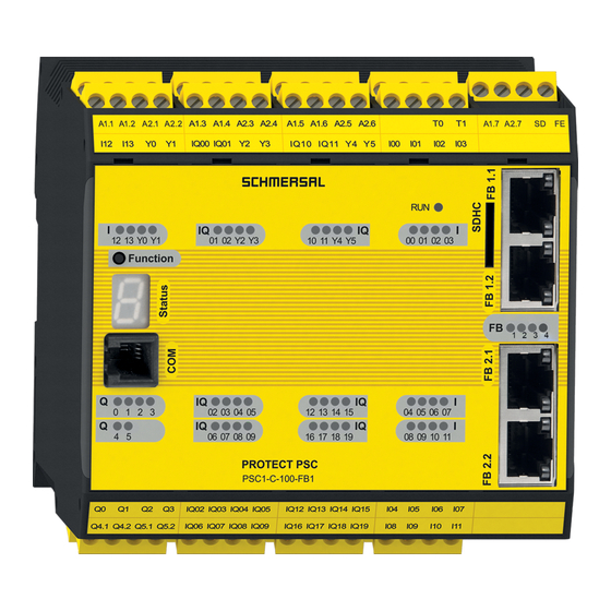
(see Section "5.5.1 Fieldbus interface connection (RJ45 socket) socket with the FB1 option Figure 1: Front view device variant (-FB1); here PSC1-C-10-FB1 No settings have to be made on the device. Installation manual PSC1-Field buses V2.2.docx Page 16 of 166... -
Page 17: Can Or Rs485-Based Device Variants (-Fb2)
(see Section "5.5.2 Fieldbus interface connection (D-SUB- socket)" socket with the FB2 option Figure 2: Front view device variant (-FB2); here PSC1-C-10-FB2 The slave address must be adapted according to Section 5.4 "Address selector switch Installation manual PSC1-Field buses V2.2.docx... -
Page 18: Diagnostic Leds
Name Function PSC1 State SDDC/SMMC communication Fieldbus status Cross communication to the F-CPU SD bus status Figure 3: Diagnostic LEDs Installation manual PSC1-Field buses V2.2.docx Page 18 of 166... -
Page 19: Table 8: Diagnostic Leds Display Functions
1 / SD Continuous Active data exchange Red/orange Flashing Error during SD bus scan Continuous SD bus error in cyclic operation No SD bus device (slave) found Table 8: Diagnostic LEDs display functions Installation manual PSC1-Field buses V2.2.docx Page 19 of 166... -
Page 20: Connection And Installation
Suitable measures must be taken to exclude faults in the event of overvoltage. Suitable measures are, for instance, lightning protection for wires outdoors, overvoltage protection for the installation indoors, protected cable laying. Measures for electromagnetic compatibility (EMC): Installation manual PSC1-Field buses V2.2.docx Page 20 of 166... -
Page 21: Installing Psc1 Modules
Safety instructions: • It is to be ensured that the power supply wires for the PSC1 and "switching wires" for the power converter are laid separately. • Signal wires and power wires for the power converter are to be laid in separate cable ducts. -
Page 22: Assembly Of Modules And Backplane Bus
5.3 Assembly of modules and backplane bus Figure 5: Assembly The devices are fitted to the rail from above at an angle and snapped downward. Further information can be found in the installation manuals for the PSC1-C-10 and PSC1-C- 100. 5.4 Address selector switch For PSC1 modules with option FB2, 2 address selection switches are mounted on the underside of the COM interface. -
Page 23: Assignment Of Connection Socket
6 Modification / dealing with changes to the device Repair It is only possible to repair a device in the factory. Warranty The warranty will be rendered void if the module is opened or modified without authorisation. Installation manual PSC1-Field buses V2.2.docx Page 23 of 166... -
Page 24: Maintenance
• Connect the fieldbus connection cable • Activate power supply Note: In principle, no plug-in connection on the PSC1 module is allowed to be disconnected or connected again while electrically live. 8 Technical data Ambient conditions Degree of protection IP 20 Ambient temperature 0°C... -
Page 25: Diagnostic Data
Total diagnostic data size: always 128 bytes, of which 16 bytes can be used for diagnostics Byte "Run" mode (2, 3, 4) Error case ( A, F) Byte 0 0...3 PSC1 mode 1, 2, 3, 4, 5, 6 = Fatal error, 7 = Alarm 0x1 (always 1) 5..7 Alive counter (3 Bit) Byte 1 0...7 Logic data (Bit ID: 48..55) -
Page 26: Psc1-C-100-X-Fb1/2 Diagnostic Data
(Logic data bit ID336 to bit ID391) Table 12: Structure for device profile 0 (= free assignment) with extension modules Offset for error number of the slave module: Offset bit data + 6 Installation manual PSC1-Field buses V2.2.docx Page 26 of 166... -
Page 27: Configuration Without Axis Extension Modules (Slave Module)
Table 13: Structure for device profile 0 (= free assignment) without extension modules Offset for error number of the master module: Offset bit data + 6 (only in bit data type "1") Installation manual PSC1-Field buses V2.2.docx Page 27 of 166... -
Page 28: Data Types
9.2.1.3.1 Bit data type "1" Byte "Run" mode (2, 3, 4) Error case ( A, F) Byte 0 0...3 PSC1 mode 1, 2, 3, 4, 5, 6 = Fatal error, 7 = Alarm 0x1 (always 1) 5..7 Alive counter (3 Bit) Byte 1 0...7 Logic data (Bit ID: 48..55) -
Page 29: Table 15: Process Data
Process data bit 56..63 BYTE 8 Process data bit 64..71 BYTE 9 Process data bit 72..79 BYTE 10 Process data bit 80..87 BYTE 11 Process data bit 88..95 Table 16: Process data Installation manual PSC1-Field buses V2.2.docx Page 29 of 166... -
Page 30: Structure For Device Profile 1 (= Only Logic Data)
9.2.2 Structure for device profile 1 (= only logic data) Byte "Run" mode (2, 3, 4) Error case ( A, F) Byte 0 0..3 PSC1 mode 1, 2, 3, 4, 5, 6 = Fatal error, 7 = Alarm 0x1 (always 1) 5..7 Alive counter (3 Bit) Byte 1 0..7... -
Page 31: Structure For Device Profile 2 (= Logic Data + Process Data For Each Slave)
9.2.3 Structure for device profile 2 (= logic data + process data for each slave) Byte "Run" mode (2, 3, 4) Error case ( A, F) Byte 0 0..3 PSC1 mode 1, 2, 3, 4, 5, 6 = Fatal error, 7 = Alarm 0x1 (always 1) 5..7 Alive counter (3 Bit) Byte 1 0..7... - Page 32 0..7 Process data axis modules slave 6 bit 24..31 Byte 120 0..7 Process data axis modules slave 6 bit 32..39 Byte 121 0..7 Process data axis modules slave 6 bit 40..47 Installation manual PSC1-Field buses V2.2.docx Page 32 of 166...
-
Page 33: Table 17: Structure For Device Profile 1 (= Logic Data + Process Data For Each Slave)
(value always 0): • Bit ID 31 • Bit ID 87 • Bit ID 143 • Bit ID 199 • Bit ID 255 • Bit ID 311 • Bit ID 367 Installation manual PSC1-Field buses V2.2.docx Page 33 of 166... -
Page 34: Sd-Bus Data
In the request, only the first byte is needed in the fieldbus as request byte for an SD slave. The second byte is not used. In the response, first the response byte and subsequently the diagnostic byte of each SD slave is transmitted to the fieldbus. Installation manual PSC1-Field buses V2.2.docx Page 34 of 166... -
Page 35: Structure Of The Sd Bytes In The Fieldbus Protocol
The content of the diagnostic byte of an SD slave depends on the status of the warning and the error bits in the corresponding response byte (Bit 6 = error warning and Bit 7 = error). The meaning of the individual bits of the SD bytes is explained in the mounting instructions of the SD devices Installation manual PSC1-Field buses V2.2.docx Page 35 of 166... -
Page 36: Reading Acyclic Data From The Sd Slave
The data byte can also include an error message as response: Hex FE: Instruction error, undefined instruction requested Hex FD: Address error, invalid slave address for the selected instruction or slave address of a unavailable SD slave selected Installation manual PSC1-Field buses V2.2.docx Page 36 of 166... -
Page 37: Table 18: Overview Of The Instructions And Response Data
(low byte) Hex: 1F Table 19: Overview of the instructions and response data The device category of a SD slave can be found in the mounting instructions of the device concerned. Installation manual PSC1-Field buses V2.2.docx Page 37 of 166... - Page 38 One or more SD slaves unavailable. Invalid data from the SD slaves. If necessary, check SD installation. Table 20: SD Master Diagnose, SD System error / Content Response byte 00, Diagnostic byte Gateway Installation manual PSC1-Field buses V2.2.docx Page 38 of 166...
-
Page 39: Assigning Ip Address (-Fb1 Option Only)
Figure 2: missing WinPcap driver message First select the network card which is connected to the respective PSC1. Note: Only network cards are listed that are connected to an active network. The IP address of the selected network card must be in the same IP address range (subnet mask) as the PSC1. - Page 40 In this list the parameters for IP-Address and/or Name of Station can be modified here for the selected device. Changes were taken over by pressing the respective buttons Set IP and Set Name. Installation manual PSC1-Field buses V2.2.docx Page 40 of 166...
-
Page 41: Commissioning And Configuration Profinet In Safeplc2 And Tia Portal (From Step 7 V10)
11 Commissioning and configuration PROFINET in SafePLC2 and TIA Portal (from Step 7 V10) PROFINET is available for all PSC1 base devices with the "-FB1" option. The "-FB1" option is always permanently integrated in the base device and represents the gateway from the CAN-based backplane bus of the PSC1 series to PROFINET. -
Page 42: Figure 10: Properties Fieldbus (Fieldbus Profinet) - Non-Safe
Installation manual Figure 10: Properties fieldbus (Fieldbus PROFINET) - non-safe Parametrisation for safe data transmission (PROFIsafe) Figure 11: Properties fieldbus (Fieldbus PROFINET) - safe Installation manual PSC1-Field buses V2.2.docx Page 42 of 166... -
Page 43: Figure 12: Properties Fieldbus (Fieldbus Profinet) - Both
Installation manual Parametrisation for non-safe and safe data transmission (PROFIsafe) Figure 12: Properties fieldbus (Fieldbus PROFINET) - both Installation manual PSC1-Field buses V2.2.docx Page 43 of 166... - Page 44 Installation manual The functional inputs and outputs must still be inserted in the "Functional scheme" and logically connected. The project and the network configuration must be transferred: "Click the "Device Interface" icon Installation manual PSC1-Field buses V2.2.docx Page 44 of 166...
- Page 45 Installation manual Click the "Connect" icon in the new dialogue. The successful connection to PSC1 is displayed in the following dialogue ("Connect icon" faded out /"Disconnect icon" faded in). Now the network configuration and the source code can be transferred.
-
Page 46: Parameter Configuration
The parameters are set using the "TIA Portal" program from Siemens AG. 11.1.1 Installing the XML file Click on "Tools" => "Manage device description files (GSD)". Select "Source path" and confirm the selection with "Install". Installation manual PSC1-Field buses V2.2.docx Page 46 of 166... - Page 47 Installation manual The device catalogue is updated. The installation result of the XML file is displayed. Installation manual PSC1-Field buses V2.2.docx Page 47 of 166...
-
Page 48: Create Project And Insert Psc1 With Profinet
Installation manual 11.1.2 Create project and insert PSC1 with PROFINET Create a new project with "Project" => "New". Assign a project name. Installation manual PSC1-Field buses V2.2.docx Page 48 of 166... - Page 49 Installation manual Call up the hardware catalogue in the "Network overview". Enter "PSC1" in the search field of the hardware catalogue and confirm with "Enter". Installation manual PSC1-Field buses V2.2.docx Page 49 of 166...
- Page 50 Installation manual Confirm the selection by double-clicking. The inserted device is displayed in the "Network Overview". Installation manual PSC1-Field buses V2.2.docx Page 50 of 166...
- Page 51 Installation manual The PSC1-C-xxx-FB must still be assigned. Click on "not assigned" and select the master control. The successful assignment is indicated by a connection line. Double-click on PSC1-C-xxx-FB... to access the "Device overview". Installation manual PSC1-Field buses V2.2.docx Page 51 of 166...
-
Page 52: Setting Up Secure Data Transmission
If you do not want to set up secure data transfer, proceed with "11.1.4 Setting up an online connection". A safe communication module "F modules" from the device catalogue must be inserted in the device overview. Installation manual PSC1-Field buses V2.2.docx Page 52 of 166... - Page 53 The "PROFIsafe" tab must be used to adjust the target address and the monitoring time. The destination address must correspond to the address preset in SafePLC2 (in the example the address 10) Installation manual PSC1-Field buses V2.2.docx Page 53 of 166...
- Page 54 To reintegrate the safe module after an F-peripheral/channel error, an acknowledgement must still be programmed. The acknowledgement request for reintegration is detected via the variable "ACK_REQ" and the acknowledgement for reintegration is sent via the variable "ACK_REI". Installation manual PSC1-Field buses V2.2.docx Page 54 of 166...
-
Page 55: Setting Up An Online Connection
Installation manual 11.1.4 Setting up an online connection To establish an online connection to the master control, click on "Connect Online" and start the search for compatible devices. Installation manual PSC1-Field buses V2.2.docx Page 55 of 166... - Page 56 Installation manual The IP address of the preselected communication card of the PC/PG may still have to be adapted. Installation manual PSC1-Field buses V2.2.docx Page 56 of 166...
- Page 57 Installation manual Installation manual PSC1-Field buses V2.2.docx Page 57 of 166...
- Page 58 PROFINET IO Device. Double-click on the desired device in the "Device Overview" and then right-click to open the menu dialogue shown below. Select the "Assign device name" function. Installation manual PSC1-Field buses V2.2.docx Page 58 of 166...
- Page 59 Installation manual In the following dialogue, accept or edit the PROFINET device name and confirm the selection with "Assign name". Installation manual PSC1-Field buses V2.2.docx Page 59 of 166...
- Page 60 Installation manual After a successful change, the status changes to "OK". Signal states can now be observed in the "Observe Variables" dialogue. Installation manual PSC1-Field buses V2.2.docx Page 60 of 166...
-
Page 61: Examples Of Non-Secure Data Transmission
SafePLC2 in bit 0 (functional output) and can be read in byte 5 (bit 0) of the configuration tool (TIA Portal). In addition, up to 32 non-safe functional inputs are available on the PSC1, via which digital information can be received from the higher-level standard controller. - Page 62 Installation manual In the following example, the functional output (Byte0, Bit 0) is written in the higher-level standard control and AND-linked to a safe input in PSC1 (Confirm Button 1). Both have a high signal, relay 1 is activated. Installation manual PSC1-Field buses V2.2.docx...
- Page 63 In the following example, the functional output (Byte0, Bit 0) is written in the higher-level standard control and AND-linked to a safe input in PSC1 (Confirm Button 1). "Confirm Button 1" has a low signal, the functional output from the standard control has a high signal, Relay 1 is not activated.
-
Page 64: Examples Of Secure Data Transmission
In the following example, the switching state of the button "Confirm Button 1" is written to PSC1 in bit 1 (f bus output 1) and can be read in byte 0 (bit 0, F bus 00..07) of the configuration tool (TIA Portal). - Page 65 In the following example, the functional output (F_Bus byte 0. bit 0) is written in the safety controller and read in the PSC1 in bit 0 (F bus input 1) and output to relay 2. Installation manual PSC1-Field buses V2.2.docx...
-
Page 66: Commissioning And Configuration Ethernet/Ip In Safeplc2 And Rslogix500
12 Commissioning and configuration EtherNet/IP in SafePLC2 and RSLogix500 EtherNet/IP is available for all PSC1 base devices with the "-FB1" option. The "-FB1" option is always permanently integrated in the base device and represents the gateway from the CAN-based backplane bus of the PSC1 series to EtherNet/IP. -
Page 67: Figure 14: Properties Fieldbus (Fieldbus Ethernet/Ip) - Non-Safe
Installation manual Figure 14: Properties fieldbus (Fieldbus EtherNet/IP) - non-safe Installation manual PSC1-Field buses V2.2.docx Page 67 of 166... - Page 68 Installation manual The functional inputs and outputs must still be inserted in the "Functional scheme" and logically connected. The project and the network configuration must be transferred: "Click the "Device Interface" icon Installation manual PSC1-Field buses V2.2.docx Page 68 of 166...
- Page 69 Installation manual Click the "Connect" icon in the new dialogue. The successful connection to PSC1 is displayed in the following dialogue ("Connect icon" faded out /"Disconnect icon" faded in). Now the network configuration and the source code can be transferred.
-
Page 70: Parameter Configuration
12.1 Parameter configuration The parameters are set using the RSLogix5000 program from Rockwell Automation, Inc. 12.1.1 Create project On the menu, click File > New > Project and create a new RSLogix5000 project. Installation manual PSC1-Field buses V2.2.docx Page 70 of 166... - Page 71 Installation manual In the tree view, right-click on "... Bus" and in the context menu on "New Module". Installation manual PSC1-Field buses V2.2.docx Page 71 of 166...
- Page 72 Installation manual Select the desired communication card and click on "Create". Then enter the IP address of your network card and confirm with "OK". Installation manual PSC1-Field buses V2.2.docx Page 72 of 166...
-
Page 73: Installing The Eds File
Installation manual 12.1.2 Installing the EDS file Click on "Tools" => "EDS Hardware Installation Tool". If necessary, confirm that you want to start the installation tool. Installation manual PSC1-Field buses V2.2.docx Page 73 of 166... - Page 74 Installation manual Select "Register to EDS file(s)" and click "Next". Select the EDS file and click "Next". Installation manual PSC1-Field buses V2.2.docx Page 74 of 166...
- Page 75 Installation manual The EDS file is checked. In the following, it is possible to change the graphical image of the slave (not recommended). Click on "Next". Installation manual PSC1-Field buses V2.2.docx Page 75 of 166...
- Page 76 Installation manual The following window gives a short summary of the installation. Click on "Next". Then click on "Finish". Installation manual PSC1-Field buses V2.2.docx Page 76 of 166...
-
Page 77: Insert Psc1
Installation manual 12.1.3 Insert PSC1 In the tree view, right-click "Ethernet" and then "New Module" in the context menu. Installation manual PSC1-Field buses V2.2.docx Page 77 of 166... - Page 78 Installation manual Select PSC1-C-xxx-FB1-EIP in the device catalogue and click on "Create". Installation manual PSC1-Field buses V2.2.docx Page 78 of 166...
- Page 79 The Rockwell Automation BOOTP-DHCP tool can be used to assign the IP address (for more information see 12.2Assigning IP addresses with the BOOTP-DHCP tool Select "Exclusive Owner" and click "OK". Installation manual PSC1-Field buses V2.2.docx Page 79 of 166...
- Page 80 Installation manual If necessary, click "Yes" to confirm your selection. Installation manual PSC1-Field buses V2.2.docx Page 80 of 166...
-
Page 81: Setting Up An Online Connection
Installation manual 12.1.4 Setting up an online connection Transfer your project by selecting "Communications" => "Go Online" in the menu. Installation manual PSC1-Field buses V2.2.docx Page 81 of 166... - Page 82 Installation manual RSLogix5000 compares the online and offline projects. Confirm the data transfer with "Download". If necessary, also confirm the following warning with "Download". Installation manual PSC1-Field buses V2.2.docx Page 82 of 166...
- Page 83 Installation manual Signal states can be observed in the "Controller Tags" dialogue. Installation manual PSC1-Field buses V2.2.docx Page 83 of 166...
-
Page 84: Examples Of Non-Secure Data Transmission
SafePLC2 in bit 0 and can be read in byte 5 (bit 0) of the configuration tool (RSLogix5000). In addition, up to 32 non-safe functional inputs are available on the PSC1, via which digital information can be received from the higher-level standard controller. - Page 85 Installation manual In the following example, the functional output (Byte0, Bit 0) is written in the higher-level standard control and AND-linked to a safe input in PSC1 (Confirm Button 1). Both have a high signal, relay 1 is activated. In the following example, the functional output (Byte0, Bit 0) is written in the higher-level standard control and AND-linked to a safe input in PSC1 (Confirm Button 1).
-
Page 86: Assigning Ip Addresses With The Bootp-Dhcp Tool
12.2 Assigning IP addresses with the BOOTP-DHCP tool Start the "BOOTP-DHCP Tool" and select "Tools" => "Network Settings". Enter the "Subnet Mask" and the IP address of the gateway. Confirm your entries with "OK". Installation manual PSC1-Field buses V2.2.docx Page 86 of 166... - Page 87 In the "Request History" select the desired slave and click on "Add to Relation List" (Alternatively you can double-click on the desired slave). Enter the IP address of the slave and confirm your entries with "OK". Installation manual PSC1-Field buses V2.2.docx Page 87 of 166...
- Page 88 Installation manual The slave is now displayed with the corresponding IP address in the "Relation List". To assign the address permanently, click on "Disable BOOTP/DHCP". Installation manual PSC1-Field buses V2.2.docx Page 88 of 166...
-
Page 89: Assigning Ip Addresses Using The Ip Administrator
As WinPcap is not necessary for Ethenet/IP you may ignore the message. missing WinPcap driver message First select the network card which is connected to the respective PSC1. Note: Only network cards are listed that are connected to an active network. The IP address of the selected network card must be in the same IP address range (subnet mask) as the PSC1. - Page 90 Notifications area. Changing an IP address To assign a new IP address to a PSC1 device, the device first must be selected in the Device List and then via Enable DHCP on selected device DHCP must be activated for this device.
-
Page 91: Commissioning And Configuration Ethercat In Safeplc2 And Twincat 3
13 Commissioning and configuration EtherCAT in SafePLC2 and TwinCat 3 EtherCAT is available for all PSC1 base devices with the "-FB1" option. The "-FB1" option is always permanently integrated in the base device and represents the gateway from the CAN-based backplane bus of the PSC1 series to EtherCAT. -
Page 92: Figure 16: Properties Fieldbus (Fieldbus Ethercat) - Non-Safe
Installation manual Figure 16: Properties fieldbus (Fieldbus EtherCAT) - non-safe Installation manual PSC1-Field buses V2.2.docx Page 92 of 166... - Page 93 Installation manual Parametrisation for safe data transmission (FSoE) Parametrisation for non-safe and safe data transmission (FSoE) Installation manual PSC1-Field buses V2.2.docx Page 93 of 166...
- Page 94 Installation manual The functional inputs and outputs must still be inserted in the "Functional scheme" and logically connected. The project and the network configuration must be transferred: "Click the "Device Interface" icon Installation manual PSC1-Field buses V2.2.docx Page 94 of 166...
- Page 95 Installation manual Click the "Connect" icon in the new dialogue. The successful connection to PSC1 is displayed in the following dialogue ("Connect icon" faded out /"Disconnect icon" faded in). Now the network configuration and the source code can be transferred.
-
Page 96: Parameter Configuration
Click in the menu on File => New => Project and create a new "TwinCAT XAE project". • Click on "SYSTEM" on the left side of the tree view and then on "Choose Target". Installation manual PSC1-Field buses V2.2.docx Page 96 of 166... - Page 97 Installation manual Click on "Search (Ethernet)". Click on "Broadcast Search". Installation manual PSC1-Field buses V2.2.docx Page 97 of 166...
- Page 98 Installation manual Select the device found and then click on "Add Route". Enter the user name in the "User Name" field and the password for the user in the "Password" field. Installation manual PSC1-Field buses V2.2.docx Page 98 of 166...
-
Page 99: Find Connected I/O Devices
The files should always be unpacked completely into the ESI directory of the EtherCAT Master. The directory can be found in TwinCAT 3.x under "\TwinCAT\3.x\Config\Io\EtherCAT". Activate in the upper navigation bar "Config Mode". If necessary, confirm the mode switch. Installation manual PSC1-Field buses V2.2.docx Page 99 of 166... - Page 100 Installation manual Right-click I/O Devices in the tree view on the left and "Scan" in the context menu. Installation manual PSC1-Field buses V2.2.docx Page 100 of 166...
- Page 101 Select the devices you want to use and confirm the selection with "OK". Only the devices that are actually present are available. Confirm the query with Yes to search for "Boxes". Installation manual PSC1-Field buses V2.2.docx Page 101 of 166...
- Page 102 Installation manual Confirm the request with "Yes" to activate "Free Run". Installation manual PSC1-Field buses V2.2.docx Page 102 of 166...
- Page 103 Installation manual The PSC1 is displayed in the tree view as Box x (KAS ComX). Installation manual PSC1-Field buses V2.2.docx Page 103 of 166...
-
Page 104: Examples Of Non-Secure Data Transmission
SafePLC2 in bit 0 and can be read in byte 5 (bit 0) of the configuration tool (TwinCAT 3). In addition, up to 32 non-safe functional inputs are available on the PSC1, via which digital information can be received from the higher-level standard controller. - Page 105 Installation manual In the following example, the functional output (Byte0, Bit 0) is written in the higher-level standard control and AND-linked to a safe input in PSC1 (Confirm Button 1). Both have a high signal, relay 1 is activated. Installation manual PSC1-Field buses V2.2.docx...
- Page 106 Installation manual Installation manual PSC1-Field buses V2.2.docx Page 106 of 166...
- Page 107 In the following example, the functional output (Byte0, Bit 0) is written in the higher-level standard control and AND-linked to a safe input in PSC1 (Confirm Button 1). "Confirm Button 1" has a low signal, the functional output from the standard control has a high signal, Relay 1 is not activated.
- Page 108 Installation manual Installation manual PSC1-Field buses V2.2.docx Page 108 of 166...
-
Page 109: Create Safety Project
Installation manual 13.1.4 Create safety project Right-click "SAFETY" in the tree view on the left and "Add New" item in the context menu. Installation manual PSC1-Field buses V2.2.docx Page 109 of 166... - Page 110 Installation manual Select "TwinCAT Default Safety Project" and specify the project name. Confirm your entries with "Add". Installation manual PSC1-Field buses V2.2.docx Page 110 of 166...
- Page 111 In this alias level (sub-node \ alias devices), corresponding "Alias Devices" are created for all safe inputs and outputs, but also for standard signals. This can also be done automatically for the safe inputs and outputs using the I/O configuration. Installation manual PSC1-Field buses V2.2.docx Page 111 of 166...
- Page 112 If the automatic import from the I/O configuration is started, a selection dialogue is opened via which the individual terminals that are to be imported automatically can be selected. Installation manual PSC1-Field buses V2.2.docx Page 112 of 166...
- Page 113 TwinCAT Safety PLC is to be executed via the "Link" button next to "Append to Task". Left-click on "Target System" in the tree view and then click on "Physical Device" in the context menu. Installation manual PSC1-Field buses V2.2.docx Page 113 of 166...
- Page 114 Installation manual Select the master device in the context menu and confirm your entry with "OK". After closing the dialogue, the Master Device is linked to the task. Installation manual PSC1-Field buses V2.2.docx Page 114 of 166...
- Page 115 "Safe Address" tab. If the address is unknown, it can be read out. Activate the Config Mode: "TWINCAT => Restart TwinCAT (Config Mode)". Confirm your selection with "OK". Installation manual PSC1-Field buses V2.2.docx Page 115 of 166...
- Page 116 Installation manual Confirm the readout of the I/O peripherals with "Yes". Confirm activation of the "Free Run" mode. Read out the hardware address by clicking on the icon shown below. Installation manual PSC1-Field buses V2.2.docx Page 116 of 166...
- Page 117 Installation manual Enter the hardware address read out into the "Safe Address" tab. Installation manual PSC1-Field buses V2.2.docx Page 117 of 166...
- Page 118 The safe FSoE address of the PSC control must correspond to the address preset in SafePLC2 (in the example the address 123). The automatic readout of the DIP switch addressing switch is not supported for PSC1 and is signalled by the system by the message shown below.
- Page 119 Left-click on "TwinSafeGroupX.sal" in the tree view to create a safety-related program. Insert logical links and assign the required variable names. The variables created are displayed in the lower navigation window under "Variables => Variable Mapping". Installation manual PSC1-Field buses V2.2.docx Page 119 of 166...
- Page 120 In the group configuration, mapping must still be performed for Error Acknowledge (e.g. for reintegration after a communication interruption). This signal is linked via the "ERR Ack" link in the navigation window under "Variable Mapping => Group Ports". Installation manual PSC1-Field buses V2.2.docx Page 120 of 166...
- Page 121 "PLC" in the tree view on the left and click on "Add New Item" in the context menu. Select "Standard PLC Project" in the following dialogue and confirm your selection with "Add". Installation manual PSC1-Field buses V2.2.docx Page 121 of 166...
- Page 122 Installation manual Right-click on "GVLs" in the tree view on the left, then click on "Add" in the context menu and then on "Global Variable List...". Select "Open" in the following dialogue. Installation manual PSC1-Field buses V2.2.docx Page 122 of 166...
- Page 123 Installation manual Enter the following instruction in the GVL: "bReset AT %Q*: BOOL; Compile your project: "Build => Build Solution". Installation manual PSC1-Field buses V2.2.docx Page 123 of 166...
- Page 124 Installation manual Click on "NonSafeProject Instance => PlcTask Outputs" on the left side of the tree view => GVL.bReset". Select "Linked to" in the following dialogue. Installation manual PSC1-Field buses V2.2.docx Page 124 of 166...
- Page 125 Installation manual Add a shortcut to the "ERR Ack" signal link. Installation manual PSC1-Field buses V2.2.docx Page 125 of 166...
- Page 126 Installation manual Now the safety-related program can be compiled. Click on "PSC1-C-10-FB1-ECFS Project (your project name)" in the tree view on the left and on the "Verify Safety Project" icon in the upper navigation bar. If your safety-related project has been compiled without errors, the project can be transferred to the EtherCAT-FSoE-capable master controller.
- Page 127 Installation manual The serial number of the target system can be read out on the left in the tree view under "PSC1-C-10-FB1-ECFS (your project name) => Target System". After the "Download" click on "Next". Installation manual PSC1-Field buses V2.2.docx Page 127 of 166...
- Page 128 Installation manual After "Final Verification" click on "Next". Click on "Finish" to end the "Activation". Installation manual PSC1-Field buses V2.2.docx Page 128 of 166...
- Page 129 Now only the hardware must be acknowledged via the previously defined "bReset- Variable" (NonSafeProject Project[your project name] => PlcTask Outputs => GVL.bReset. Click on Force and set the value in the following dialogue to "1" and then to "0". Installation manual PSC1-Field buses V2.2.docx Page 129 of 166...
- Page 130 In the following example, the switching state of the button "Confirm Button 1" is written to SafePLC2 in bit 0 (F-Bus Output 1) and can be read in byte 0 (bit 0, PSC1_F_Bus_Bit_0_Input) of the configuration tool (TC3). Installation manual PSC1-Field buses V2.2.docx Page 130 of 166...
- Page 131 In the following example, the functional output (PSC1_F_Bus_Bit_0_Output byte 0. bit 0) is written in the safety controller and read in the PSC1 in bit 0 (F bus input 1). Installation manual PSC1-Field buses V2.2.docx...
-
Page 132: Commissioning And Configuration Proifbus In Safeplc2 And Tia Portal (From Step 7 V10)
14 Commissioning and configuration PROIFBUS in SafePLC2 and TIA Portal (from Step 7 V10) PROFBUS is available for all PSC1 base devices with the "-FB2" option. The "-FB2" option is always permanently integrated in the base device and represents the gateway from the CAN-based backplane bus of the PSC1 series to PROFIBUS. -
Page 133: Figure 18: Properties Fieldbus (Fieldbus Profibus) - Non-Safe
Installation manual Figure 18: Properties fieldbus (Fieldbus PROFIBUS) - non-safe Parametrisation for safe data transmission (PROFIsafe) Figure 19: Properties fieldbus (Fieldbus PROFIBUS) - safe Installation manual PSC1-Field buses V2.2.docx Page 133 of 166... -
Page 134: Figure 20: Properties Fieldbus (Fieldbus Profibus) - Both
Installation manual Parametrisation for non-safe and safe data transmission (PROFIsafe) Figure 20: Properties fieldbus (Fieldbus PROFIBUS) - both Installation manual PSC1-Field buses V2.2.docx Page 134 of 166... - Page 135 Installation manual The functional inputs and outputs must still be inserted in the "Functional scheme" and logically connected. The project and the network configuration must be transferred: "Click the "Device Interface" icon Installation manual PSC1-Field buses V2.2.docx Page 135 of 166...
- Page 136 Installation manual Click the "Connect" icon in the new dialogue. The successful connection to PSC1 is displayed in the following dialogue ("Connect icon" faded out /"Disconnect icon" faded in). Now the network configuration and the source code can be transferred.
-
Page 137: Parameter Configuration
Installation manual 14.1 Parameter configuration The parameters are set using the "TIA Portal" program from Siemens AG. Installing the XML file Click on "Tools" => "Manage device description files (GSD)". Installation manual PSC1-Field buses V2.2.docx Page 137 of 166... - Page 138 Select "Source path" and confirm the selection with "Install". If you use the safety-related fieldbus "PROFIBUS - PROFIsafe" or carry out your project planning with TIA, please use "kas0fd5.gsd (PSC1-C-10-x-FB2 and PSC1-C-100-FB2 PROFIBUS DP-V1 extension with ProfiSAFE support.)". If you use the non-safety-related fieldbus "PROFIBUS" and carry out your project planning with STEP7, please use "kas0fd4.gsd (PSC1-C-10-x-FB2 and PSC1-C-100-FB2 PROFIBUS...
- Page 139 Installation manual The installation result of the XML file is displayed. Installation manual PSC1-Field buses V2.2.docx Page 139 of 166...
-
Page 140: Create Project And Insert Psc1 With Profibus
Installation manual 14.1.1 Create project and insert PSC1 with PROFIBUS Create a new project with "Project" => "New". Assign a project name. Installation manual PSC1-Field buses V2.2.docx Page 140 of 166... - Page 141 Installation manual Call up the hardware catalogue in the "Network overview". Enter "PSC1" in the search field of the hardware catalogue and confirm with "Enter". Installation manual PSC1-Field buses V2.2.docx Page 141 of 166...
- Page 142 Installation manual Confirm the selection by double-clicking. The inserted device is displayed in the "Network Overview" Installation manual PSC1-Field buses V2.2.docx Page 142 of 166...
- Page 143 Installation manual The PSC1-C-xxx-FB must still be assigned. Click on "not assigned" and select the master control. The successful assignment is indicated by a connection line Double-click on PSC1-C-xxx-FB... to access the "Device overview". Installation manual PSC1-Field buses V2.2.docx Page 143 of 166...
- Page 144 Click on the communication module to access the properties of the module. The PSC1 PROFIBUS address must be entered in the "Address" tab. The address entered must match the address preset on the PSC1 with the installed rotary switches Installation manual PSC1-Field buses V2.2.docx...
-
Page 145: Setting Up Secure Data Transmission
The "PROFIsafe" tab must be used to adjust the target address and the monitoring time. The destination address must correspond to the address preset in SafePLC2 (in the example the address 10). Installation manual PSC1-Field buses V2.2.docx Page 145 of 166... - Page 146 The acknowledgement request for reintegration is detected via the variable "ACK_REQ" and the acknowledgement for reintegration is sent via the variable "ACK_REI". When you have finished the project planning, proceed with "14.1.4 Setting up an online connection". Installation manual PSC1-Field buses V2.2.docx Page 146 of 166...
-
Page 147: Setting Up Non-Secure Data Transmission
Installation manual 14.1.3 Setting up non-secure data transmission The following steps describe the project planning for the non-safety-related PROFIBUS fieldbus. Call up the device overview of PSC1. Delete the PROFIsafe_1 module. Installation manual PSC1-Field buses V2.2.docx Page 147 of 166... - Page 148 Installation manual Insert an Empty Module. Compile the device configuration. Installation manual PSC1-Field buses V2.2.docx Page 148 of 166...
-
Page 149: Setting Up An Online Connection
Installation manual 14.1.4 Setting up an online connection To establish the online connection to the master control, you must: Click on "Connect online" and start the search for compatible devices. Installation manual PSC1-Field buses V2.2.docx Page 149 of 166... - Page 150 Installation manual The IP address of the preselected communication card of the PC/PG may still have to be adapted. Installation manual PSC1-Field buses V2.2.docx Page 150 of 166...
- Page 151 Installation manual Installation manual PSC1-Field buses V2.2.docx Page 151 of 166...
- Page 152 Installation manual Signal states can now be observed in the "Observe Variables" dialogue. Installation manual PSC1-Field buses V2.2.docx Page 152 of 166...
-
Page 153: Examples Of Non-Secure Data Transmission
SafePLC2 in bit 0 and can be read in byte 5 (bit 0) of the configuration tool (TIA). In addition, up to 32 non-safe functional inputs are available on the PSC1, via which digital information can be received from the higher-level standard controller. - Page 154 Installation manual In the following example, the functional output (Byte0, Bit 0) is written in the higher-level standard control and AND-linked to a safe input in PSC1 (Confirm Button 1). Both have a high signal, relay 1 is activated. Installation manual PSC1-Field buses V2.2.docx...
- Page 155 In the following example, the functional output (Byte0, Bit 0) is written in the higher-level standard control and AND-linked to a safe input in PSC1 (Confirm Button 1). "Confirm Button 1" has a low signal, the functional output from the standard control has a high signal, Relay 1 is not activated.
-
Page 156: Examples Of Secure Data Transmission
SafePLC2 in bit 1 (f bus output 1) and can be read in byte 0 (bit 0, F bus 00..07) of the configuration tool (TIA Portal). The last four bytes are intended for CRC control. Installation manual PSC1-Field buses V2.2.docx Page 156 of 166... -
Page 157: Examples Of Secure Data Transmission
In the following example, the switching state of the button "Confirm Button 1" is written to PSC1 in bit 1 (f bus output 1) and can be read in byte 0 (bit 0, F bus 00..07) of the configuration tool (TIA Portal). - Page 158 Installation manual In addition, up to 96 safe functional inputs are available on the PSC1, via which digital information can be received by the higher-level safety controller. In the following example, the functional output (F_Bus byte 0. bit 0) is written in the safety controller and read in the PSC1 in bit 0 (F bus input 1).
-
Page 159: Commissioning And Configuration Canopen
CANopen is available for all PSC1 base devices (starting from COM-Firmwarerelease 1.8.1) with the "-FB2" option. The "-FB2" option is always permanently integrated in the base device and represents the gateway from the CAN-based backplane bus of the PSC1 series to CANopen. - Page 160 Installation manual …and in the fieldbus properties • Type - CANOPEN must be selected. This configuration is then transferred via Device Interface -> Connect -> Send Network Configuration to the device. Installation manual PSC1-Field buses V2.2.docx Page 160 of 166...
-
Page 161: Integrating The Device Description File
Installation manual The following section shows an example of commissioning a PSC1 with CANopen interface in a Codesys setting. 15.1 Integrating the device description file Via the device repository first install .eds file and thereby making it available for projects. -
Page 162: Creating A New Project
Installation manual 15.2 Creating a new project In order to integrate a CANopen device into the hardware configuration, a CANbus master..and a CANopen manager are required. Installation manual PSC1-Field buses V2.2.docx Page 162 of 166... - Page 163 Finally, the PSC1 is added. Via ‘Edit object’ now the participant address and the process data objects (PDO) can be modified. The address is set according to the setting of the PSC1 (see Chapter 5.4). Installation manual PSC1-Field buses V2.2.docx...
- Page 164 If further PDOs are required, they must be activated manually. After the activation of the listed PDOs, the COB-IDs for the new PDOs must often also be entered, but in most cases this is done automatically or by confirming the proposed COB-IDs. Installation manual PSC1-Field buses V2.2.docx Page 164 of 166...
- Page 165 Installation manual Installation manual PSC1-Field buses V2.2.docx Page 165 of 166...
- Page 166 Installation manual EC declaration of conformity for safety components in the context of the EC directive Installation manual PSC1-Field buses V2.2.docx Page 166 of 166...
Need help?
Do you have a question about the PSC1 and is the answer not in the manual?
Questions and answers