Sign In
Upload
Download
Table of Contents
Contents
Add to my manuals
Delete from my manuals
Share
URL of this page:
HTML Link:
Bookmark this page
Add
Manual will be automatically added to "My Manuals"
Print this page
×
Bookmark added
×
Added to my manuals
Manuals
Brands
Beckhoff Manuals
Touch terminals
KS31 2 Series
Manual
Beckhoff KS31 2 Series Manual
Two channel accurate analog terminals
Hide thumbs
1
2
3
4
5
6
7
8
9
10
11
12
13
14
15
16
17
18
19
20
21
22
23
24
25
26
27
28
29
30
31
32
33
34
35
36
37
38
39
40
41
42
43
44
45
46
47
48
49
50
51
52
53
54
55
56
57
58
59
60
61
62
63
page
of
63
Go
/
63
Contents
Table of Contents
Bookmarks
Table of Contents
Table of Contents
Foreword
Notes on the Documentation
Safety Instructions
Documentation Issue Status
Product Overview
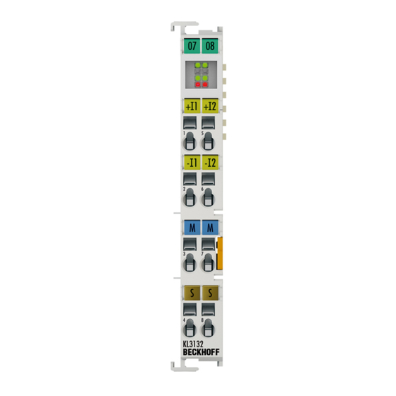
Kl3132, Kl3162, Kl3172, Kl3182
Introduction
Fig. 1 KL3132
Technical Data
Kl3142, Kl3152
Introduction
Technical Data
Leds
Fig. 3 Leds
Basic Function Principles
Fig. 4 Differential Measuring
Continuative Documentation for I/O Components with Analog in and Outputs
Mounting and Wiring
Instructions for ESD Protection
Fig. 5 Spring Contacts of the Beckhoff I/O Components
Installation on Mounting Rails
Fig. 6 Attaching on Mounting Rail
Fig. 7 Disassembling of Terminal
Disposal
Fig. 8 Power Contact on Left Side
Fig. 10 Pluggable Wiring
Connection
Fig. 9 Standard Wiring
Connection System
Fig. 11 High Density Terminals
Wiring
Fig. 12 Connecting a Cable on a Terminal Point
Shielding
Fig. 14 KL3142 - Contact Assignment
Contact Assignment
Fig. 13 KL3132 - Contact Assignment
ATEX - Special Conditions (Standard Temperature Range)
Continuative Documentation for ATEX and Iecex
Application Example for KL3172-0000
Fig. 15 KL3172-0000 - Application Example
Configuration Software KS2000
KS2000 - Introduction
Fig. 16 KS2000 Configuration Software
Parameterization with KS2000
Fig. 17 Display of the Fieldbus Station in KS2000
Fig. 18 KS2000 Branch for Channel 1 of the KL3172
Register
Fig. 19 Register View in KS2000
Settings
Fig. 20 Settings Via KS2000
Sample Program for Register Communication Via Ethercat on KL3314 Exemplary
Fig. 21 Settings of KL3314 Via Visualization of Twincat 3
Fig. 22 Opening the *. Tnzip Archive
Fig. 23 Search of the Existing HW Configuration for the Ethercat Configuration of the Example
Data Structures
Process Image
Mapping
Control and Status Byte
Register Overview
Fig. 2 KL3142
Register Description
Examples of Register Communication
Example 1: Reading the Firmware Version from Register 9
Example 2: Writing to an User Register
Appendix
Beckhoff Identification Code (BIC)
Fig. 24 BIC as Data Matrix Code (DMC, Code Scheme ECC200)
Fig. 25 Example DMC 1P072222Sbtnk4P562D71Kel1809 Q1 51S678294
Table of Figures
Advertisement
Quick Links
Download this manual
Documentation | EN
KL31x2/KS31x2
Two Channel Accurate Analog Terminals
2023-01-31 | Version: 2.6.0
Table of
Contents
Previous
Page
Next
Page
1
2
3
4
5
Advertisement
Chapters
Table of Contents
3
Table of Figures
61
Table of Contents
Need help?
Do you have a question about the KS31 2 Series and is the answer not in the manual?
Ask a question
Questions and answers
Related Manuals for Beckhoff KS31 2 Series
Touch terminals Beckhoff KL31 2 Series Documentation
Two channel accurate analog terminals (56 pages)
Touch terminals Beckhoff KS3356 Documentation
Accurate 1 channel terminal for resistance bridges (55 pages)
Touch terminals Beckhoff KL2751 Documentation
Single channel universal dimmer terminals (54 pages)
Touch terminals Beckhoff KL2 Series Manual
Digitale output terminals (40 pages)
Touch terminals Beckhoff KL3208-0010 Documentation
Eight channel input terminals for pt1000, ni1000, ntc (49 pages)
Touch terminals Beckhoff KL2532 Documentation
Two channel power stage terminals for dc motors (65 pages)
Touch terminals Beckhoff KL6811 Documentation
Dali/dsi master terminal with integrated power supply (60 pages)
Touch terminals Beckhoff KL17 Series Manual
Digital input terminals (34 pages)
Touch terminals Beckhoff KL3208 Manual
Eight channel input terminals for pt1000, ni1000, ntc (56 pages)
Touch terminals Beckhoff KL26 Series. KS26 Series Documentation
Relais output terminals (47 pages)
Touch terminals Beckhoff KS6031 Documentation
Serial interface terminals (53 pages)
Touch terminals Beckhoff KS6041 Documentation
Serial interface terminals (53 pages)
Touch terminals Beckhoff KS3222 Documentation
2 channel accurate input terminals for pt100 (rtd) (45 pages)
Touch terminals Beckhoff KS2535, KL2545 Manual
Pulse width current terminals (54 pages)
Touch terminals Beckhoff KS2542 Manual
Two channel output stage terminals for dc motors (46 pages)
Touch terminals Beckhoff KL6021 Documentation
Serial interface terminals, rs485 (rs422) (45 pages)
This manual is also suitable for:
Kl31 2 series
Kl3132
Kl3162
Kl3172
Kl3182
Table of Contents
Print
Rename the bookmark
Delete bookmark?
Delete from my manuals?
Login
Sign In
OR
Sign in with Facebook
Sign in with Google
Upload manual
Upload from disk
Upload from URL


Need help?
Do you have a question about the KS31 2 Series and is the answer not in the manual?
Questions and answers