
Related Manuals for Beckhoff KL3208-0010


Summary of Contents for Beckhoff KL3208-0010
- Page 1 Documentation KL3208-0010, KL3228-0000, KS3228-0000 Eight channel input terminals for PT1000, NI1000, NTC Version: 3.1.0 Date: 2019-02-19...
-
Page 3: Table Of Contents
1 Foreword .............................. 5 Notes on the documentation...................... 5 Safety instructions .......................... 6 Documentation issue status ...................... 7 2 Product overview............................ 9 KL3208-0010 - Introduction ....................... 9 KL3228-0000 - Introduction ...................... 10 Technical data .......................... 11 3 Mounting and wiring.......................... 12 Instructions for ESD protection ...................... 12 Installation on mounting rails ...................... 12 Installation instructions for enhanced mechanical load capacity ............. 16... - Page 4 Table of contents Version: 3.1.0 KL3208-0010, KL3228-0000, KS3228-0000...
-
Page 5: Foreword
The TwinCAT Technology is covered, including but not limited to the following patent applications and patents: EP0851348, US6167425 with corresponding applications or registrations in various other countries. ® EtherCAT is registered trademark and patented technology, licensed by Beckhoff Automation GmbH, Germany. Copyright © Beckhoff Automation GmbH & Co. KG, Germany. -
Page 6: Safety Instructions
All the components are supplied in particular hardware and software configurations appropriate for the application. Modifications to hardware or software configurations other than those described in the documentation are not permitted, and nullify the liability of Beckhoff Automation GmbH & Co. KG. Personnel qualification This description is only intended for trained specialists in control, automation and drive engineering who are familiar with the applicable national standards. -
Page 7: Documentation Issue Status
(standard temperature range)" and "ATEX - Special conditions (extended temperature range)" 2.2.0 • Process data corrected 2.1.0 • KS2000 configuration mask for KL3208-0010 added • Technical data updated • Register description updated • Information on basic function principles expanded • Approvals extended •... - Page 8 FF - firmware version HH - hardware version Sample with ser. no.: 20 09 3A 00: 20 - week of production 20 09 - year of production 2009 3A - firmware version 3A 00 - hardware version 00 Version: 3.1.0 KL3208-0010, KL3228-0000, KS3228-0000...
-
Page 9: Product Overview
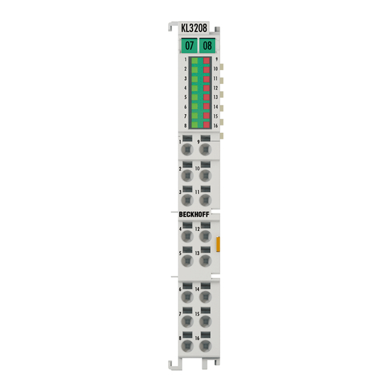
Product overview Product overview KL3208-0010 - Introduction Fig. 1: KL3208-0010 The KL3228-0010 analog input terminal enables connection of eight resistance sensors. The Bus Terminal's circuitry can handle sensors using the 2-wire technique. Linearization over the entire, freely selectable temperature range is realized with the aid of a microprocessor. -
Page 10: Kl3228-0000 - Introduction
The terminal has a resolution of 0.1 °C; the standard setting is the sensor type PT1000. The error LEDs indicate sensor faults (e.g. a broken wire). Version: 3.1.0 KL3208-0010, KL3228-0000, KS3228-0000... -
Page 11: Technical Data
Installation instructions for enhanced mechanical load capacity [} 16] EMC immunity/emission conforms to EN 61000-6-2 / EN 61000-6-4 Protection class IP20 Installation position variable Approval ATEX (extended temperature ATEX (standard temperature range) [} 25], range) [} 24], cULus cULus KL3208-0010, KL3228-0000, Version: 3.1.0 KS3228-0000... -
Page 12: Mounting And Wiring
• Each assembly must be terminated at the right hand end with an EL9011 or EL9012 bus end cap, to en- sure the protection class and ESD protection. Fig. 3: Spring contacts of the Beckhoff I/O components Installation on mounting rails... -
Page 13: Fig. 4 Attaching On Mounting Rail
To mount the mounting rails with a height of 7.5 mm under the terminals and couplers, you should use flat mounting connections (e.g. countersunk screws or blind rivets). KL3208-0010, KL3228-0000, Version: 3.1.0 KS3228-0000... -
Page 14: Fig. 5 Disassembling Of Terminal
EL91xx, EL92xx) interrupt the power contacts and thus represent the start of a new supply rail. PE power contact The power contact labeled PE can be used as a protective earth. For safety reasons this contact mates first when plugging together, and can ground short-circuit currents of up to 125 A. Version: 3.1.0 KL3208-0010, KL3228-0000, KS3228-0000... -
Page 15: Fig. 6 Power Contact On Left Side
Power Feed Terminals can be released and pulled at least 10 mm from the group of terminals. WARNING Risk of electric shock! The PE power contact must not be used for other potentials! KL3208-0010, KL3228-0000, Version: 3.1.0 KS3228-0000... -
Page 16: Installation Instructions For Enhanced Mechanical Load Capacity
The Bus Terminal system offers different connection options for optimum adaptation to the respective application: • The terminals of ELxxxx and KLxxxx series with standard wiring include electronics and connection level in a single enclosure. Version: 3.1.0 KL3208-0010, KL3228-0000, KS3228-0000... -
Page 17: Fig. 7 Standard Wiring
The overview and nomenclature of the product names for ESxxxx and KSxxxx series has been retained as known from ELxxxx and KLxxxx series. High Density Terminals (HD Terminals) Fig. 9: High Density Terminals KL3208-0010, KL3228-0000, Version: 3.1.0 KS3228-0000... -
Page 18: Wiring
Do not turn the screwdriver or move it alternately (don't toggle). 2. The wire can now be inserted into the round terminal opening without any force. 3. The terminal point closes automatically when the pressure is released, holding the wire securely and permanently. Version: 3.1.0 KL3208-0010, KL3228-0000, KS3228-0000... -
Page 19: Shielding
Wire size width (conductors with a wire end sleeve) 0.14 ... 0.75 mm Wire size width (ultrasonically “bonded" conductors) only 1.5 mm Wire stripping length 8 ... 9 mm 3.4.3 Shielding Shielding Encoder, analog sensors and actors should always be connected with shielded, twisted paired wires. KL3208-0010, KL3228-0000, Version: 3.1.0 KS3228-0000... -
Page 20: Kl3208-0010 - Connection
Mounting and wiring KL3208-0010 - Connection Fig. 11: KL3208-0010 - Connection Terminal point Connection for PT sensor channel 1 PT sensor channel 2 PT sensor channel 3 PT sensor channel 4 PT sensor channel 5 PT sensor channel 6 PT sensor channel 7... -
Page 21: Kl3228-0000 - Connection
KL3228 and KL9187. This voltage drop can falsify the measured values of the KL3228, since the back wires of the PT sensors are also routed via the power contact (0 V). See Positioning within the Bus Terminal Block [} 22] KL3208-0010, KL3228-0000, Version: 3.1.0 KS3228-0000... -
Page 22: Kl3228 - Positioning Within The Bus Terminal Block
The KL3228 drives a current through the sensor S1. This current similarly flows back to the KL3228 via the power contact marked in yellow. The voltage drop U thus causes a measuring error during the resistance measurement by the KL3228. Version: 3.1.0 KL3208-0010, KL3228-0000, KS3228-0000... -
Page 23: Fig. 14 Kl3228/Kl9187 - Example For Good Positioning
The current from the load resistors R1 and R2 does not flow back via the power contact marked in yellow (between KL3228 and KL9187). The voltage drop U at this power contact can thus be neglected. No additional measuring error occurs during the resistance measurement by the KL3228. KL3208-0010, KL3228-0000, Version: 3.1.0 KS3228-0000... -
Page 24: Atex - Special Conditions (Standard Temperature Range)
80°C at the wire branching points, then cables must be selected whose tempera- ture data correspond to the actual measured temperature values! • Observe the permissible ambient temperature range of 0 to 55°C for the use of Beckhoff fieldbus compo- nents standard temperature range in potentially explosive areas! •... -
Page 25: Atex - Special Conditions (Extended Temperature Range)
80°C at the wire branching points, then cables must be selected whose tempera- ture data correspond to the actual measured temperature values! • Observe the permissible ambient temperature range of -25 to 60°C for the use of Beckhoff fieldbus com- ponents with extended temperature range (ET) in potentially explosive areas! •... -
Page 26: Atex Documentation
Notes about operation of the Beckhoff terminal systems in potentially explosive ar- eas (ATEX) Pay also attention to the continuative documentation Notes about operation of the Beckhoff terminal systems in potentially explosive areas (ATEX) that is available in the download area of the Beckhoff homepage http:\\www.beckhoff.com! Version: 3.1.0... -
Page 27: Configuration Software Ks2000
Fieldbus Box modules with the aid of which settings can be modified easily. Alternatively, you have full access to all internal registers of the bus couplers and intelligent terminals. Refer to the register description for the meanings of the registers. KL3208-0010, KL3228-0000, Version: 3.1.0 KS3228-0000... -
Page 28: Parameterization With Ks2000
• a KL9010 bus end terminal Display of the KL3228 in KS2000 The KL3228 eight-channel analog terminal is displayed by the KS2000 Configuration Software as two four-channel analog terminals. However, you can parameterize the eight channels in the usual way. Version: 3.1.0 KL3208-0010, KL3228-0000, KS3228-0000... -
Page 29: Fig. 16 Display Of The Fieldbus Station In Ks2000
The right-hand KS2000 window contains a graphic display of the fieldbus station terminals. In the tree structure of the left-hand window, click on the plus-sign next to the terminal whose parameters you wish to change (item 2 in the example). KL3208-0010, KL3228-0000, Version: 3.1.0 KS3228-0000... -
Page 30: Fig. 17 Ks2000 Tree Branch For Kl3228-0000
For the KL3214, the branches Register, Settings and ProcData are displayed: • Register enables direct access to the KL3228 registers. • A dialog mask for the parameterization of the KL3228 can be found under Settings [} 32]. • ProcData displays the KL3228 process data. Version: 3.1.0 KL3208-0010, KL3228-0000, KS3228-0000... -
Page 31: Settings For Kl3208-0010
Configuration Software KS2000 Settings for KL3208-0010 The dialog mask for the parameterization of the KL3208-0010 can be found under Settings. Fig. 18: KL3208-0010 - Settings dialog Operation mode Here you can activate • activate the user scaling (enUsrScale, R32.0 [} 40]) and •... -
Page 32: Settings For Kl3228-0000
This example program (TwinCAT 3) provides change of single register values of the KL3314 as selection of the element type, characteristical settings of the feature register R32 and user scaling offset and gain (R33/ R34) similar as per KS2000. Version: 3.1.0 KL3208-0010, KL3228-0000, KS3228-0000... -
Page 33: Fig. 20: Settings Of Kl3314 Via Visualisation Of Twincat 3
Preparations for starting the sample programs (tnzip file / TwinCAT 3) • Click on the download button to save the Zip archive locally on your hard disk, then unzip the *.tnzip archive file in a temporary folder. Fig. 21: Opening the *. tnzip archive KL3208-0010, KL3228-0000, Version: 3.1.0 KS3228-0000... -
Page 34: Fig. 22 Search Of The Existing Hw Configuration For The Ethercat Configuration Of The Example
"Change NetId..." have to be selected. The first 4 numbers of the NetId of the target computer have to be entered; the both last values are 4.1 usually. Example: ◦ NetId of project: myComputer (123.45.67.89.1.1) ◦ Entry via „Change NetId...“: 123.45.67.89.4.1 Version: 3.1.0 KL3208-0010, KL3228-0000, KS3228-0000... -
Page 35: Access From The User Program
CB1 ... CB8: control bytes of channels 1 to 8 DataIN1 ... DataIN8: input words of channels 1 to 8 DataOUT1 ... DataOUT8: output data words of channels 1 to 8 (are used for register communication) KL3208-0010, KL3228-0000, Version: 3.1.0 KS3228-0000... -
Page 36: Control And Status Bytes
SB1.0 Name RegAccess Error Overrange Underrange Name Description SB1.7 RegAccess Acknowledgement for process data mode SB1.6 Error General error bit SB1.5 ... reserved SB1.2 SB1.1 Overrange Process data too large SB1.0 Underrange Process data too small Version: 3.1.0 KL3208-0010, KL3228-0000, KS3228-0000... -
Page 37: Register Communication
SB1.3 SB1.2 SB1.1 SB1.0 Name RegAccess R/W Reg. no. Name Description SB1.7 RegAccess 1 Acknowledgement for register access SB1.6 Read access SB1.5 to Reg. no. Number of the register that was read or written. SB1.0 KL3208-0010, KL3228-0000, Version: 3.1.0 KS3228-0000... -
Page 38: Register Overview
Lower range limit for user-defined NTC 0xFFD8 65496 SEEPROM R44 [} 41]* Upper range limit for user-defined NTC 0x0082 SEEPROM R45 [} 41]* R46…R63 reserved 0x0000 SEEPROM *) Supported only by KL3208-0010 from firmware version 1C and hardware version 01 Version: 3.1.0 KL3208-0010, KL3228-0000, KS3228-0000... -
Page 39: Register Description
The command register of KL3228 is currently not used. R8: Terminal description The terminal identifier is contained in register R8: • KL3208-0010: 0x0C88 (3208 • KL3228-0000: 0x0C9C (3228 R9: Firmware version Register R9 contains the ASCII coding of the terminal's firmware version, e.g. 0x3141 = '1A'. The '0x31' corresponds here to the ASCII character '1', while the '0x41' represents the ASCII character 'A'. - Page 40 This register contains the gain of the user scaling. User scaling can be activated in the feature register via bit R32.0 [} 40]. R37: Filter constant of the A/D converter Value in R37 First Notch Conversion time 0x0000 25 Hz 250 ms 0x0050 100 Hz 65 ms 0x00A0 50 Hz 125 ms 0x0140 25 Hz 250 ms 0x0280 12.5 Hz 500 ms Version: 3.1.0 KL3208-0010, KL3228-0000, KS3228-0000...
- Page 41 Access from the user program R39: Further elements Register R39 is supported by KL3208-0010 from firmware version 1C and hardware version 01 (Default: 0 Setting R39 increases the conversion time to one second per channel As soon as register R39 is not equal to 0 for one channel of the terminal, the conversion time for all channels is increased to about 1 second per channel, automatically and irrespective of the sensor type, in order to optimize the measuring accuracy.
-
Page 42: Examples Of Register Communication
• Bit 0.6 set means: writing to the register. • Bits 0.5 to 0.0 specify the register number 31 with 01 1111 • The output data word (byte 1 and byte 2) contains the code word (0x1235) for deactivating write protection. Version: 3.1.0 KL3208-0010, KL3228-0000, KS3228-0000... - Page 43 The bits of the feature register change the properties of the terminal and have a different meaning, depend- ing on the type of terminal. Refer to the description of the feature register of your terminal (chapter Register description) regarding the meaning of the individual bits before changing the values. KL3208-0010, KL3228-0000, Version: 3.1.0 KS3228-0000...
- Page 44 • The terminal returns a value as a receipt in the status byte that differs only in bit 0.6 from the value of the control byte. • The input data word (byte 1 and byte 2) is of no importance after the write access. Any values still displayed are invalid! Version: 3.1.0 KL3208-0010, KL3228-0000, KS3228-0000...
-
Page 45: Twincat
The general use of hardware and software from the open PC world requires some checking: Unsuitable components can upset the PC system. Beckhoff integrates a handy display of the real-time jitter in order to provide administrators with a simple means of evaluating hardware and software. A system message during operation can draw attention to error states. - Page 46 According to the requirement for operating resources, the TwinCAT software devices can be distributed: TwinCAT PLC programs can be executed on PCs and on Beckhoff Bus Terminal controllers. A "message router" manages and distributes all the messages, both in the system and via TCP/IP connections. PC systems can be connected to one another by TCP/IP;...
-
Page 47: Programming
KL3208, KL3228 - Configuration with Function blocks The function blocks FB_KL3208Config and FB_KL3208Config can be used to configure the KL3208 and KL3228 terminals. A more detailed description can be found in the Beckhoff Information System. FB_KL3208Config: TwinCAT2: TwinCAT PLC Lib: I/O functions/Bus Terminal configuration... -
Page 48: Appendix
Beckhoff's branch offices and representatives Please contact your Beckhoff branch office or representative for local support and service on Beckhoff products! The addresses of Beckhoff's branch offices and representatives round the world can be found on her internet pages: http://www.beckhoff.com You will also find further documentation for Beckhoff components there. - Page 49 List of illustrations List of illustrations Fig. 1 KL3208-0010 ..........................Fig. 2 KL3228 ............................Fig. 3 Spring contacts of the Beckhoff I/O components................. Fig. 4 Attaching on mounting rail ......................Fig. 5 Disassembling of terminal......................Fig. 6 Power contact on left side......................
Need help?
Do you have a question about the KL3208-0010 and is the answer not in the manual?
Questions and answers