
Subscribe to Our Youtube Channel
Related Manuals for Beckhoff KL2 Series


Summary of Contents for Beckhoff KL2 Series
- Page 1 Documentation | EN KL2xxx and KS2xxx Digitale output terminals 10.09.2020 | Version: 3.0.0...
-
Page 3: Table Of Contents
Table of contents Table of contents 1 Foreword .............................. 5 Notes on the documentation...................... 5 Safety instructions .......................... 6 Documentation issue status ...................... 7 2 Product overview............................ 8 KL2xxx terminal overview ........................ 8 KL2012, KL2022, KL2032 - Introduction ................... 8 2.2.1 KL2012, KL2022, KL2032 - Technical data .............. 10 2.2.2 KL2012 - LEDs and connection .................. - Page 4 Table of contents Version: 3.0.0 KL2xxx and KS2xxx...
-
Page 5: Foreword
EP1590927, EP1789857, EP1456722, EP2137893, DE102015105702 with corresponding applications or registrations in various other countries. ® EtherCAT is registered trademark and patented technology, licensed by Beckhoff Automation GmbH, Germany. Copyright © Beckhoff Automation GmbH & Co. KG, Germany. The reproduction, distribution and utilization of this document as well as the communication of its contents to others without express authorization are prohibited. -
Page 6: Safety Instructions
All the components are supplied in particular hardware and software configurations appropriate for the application. Modifications to hardware or software configurations other than those described in the documentation are not permitted, and nullify the liability of Beckhoff Automation GmbH & Co. KG. Personnel qualification This description is only intended for trained specialists in control, automation and drive engineering who are familiar with the applicable national standards. -
Page 7: Documentation Issue Status
Foreword Documentation issue status Version Comment 3.0.0 • Migration • Structure update • Technical data updated • Installation instructions for enhanced mechanical load capacity added • Revision status updated Firmware and hardware versions Documentation KL2012 KL2022 KL2032 KL2114 Version Firmware Hardware Firmware Hardware... -
Page 8: Product Overview
Product overview Product overview KL2xxx terminal overview Digital Output Terminals Terminal Number of outputs Current Comment 0.5 A KL2012 [} 8] 2.0 A KL2022 [} 8] 0.5 A protected against reverse polarity connection KL2032 [} 8] 0.5 A KL2114 [} 14] 0.5 A protected against reverse polarity connection KL2134 [} 14] 0.5 A KL2404 [} 18] 0.5 A... -
Page 9: Fig. 2 Kl2022 - 2-Channel Digital Output Terminal, 24 Vdc, 2 A
Product overview Fig. 2: KL2022 – 2-channel digital output terminal, 24 V , 2 A Fig. 3: KL2032 – 2-channel digital output terminal, 24 V , 0.5 A, protected against reverse polarity connection KL2xxx and KS2xxx Version: 3.0.0... -
Page 10: Kl2012, Kl2022, Kl2032 - Technical Data
Product overview Two-channel, digital output terminal, 24 V The KL2012, KL2022 and KL2032 digital output terminals connect the binary control signals from the automation unit on to the actuators at the process level with electrical isolation. The KL2012 and KL2022 versions handle different load currents, and their outputs are protected against overload (only KL2012) and short circuit. -
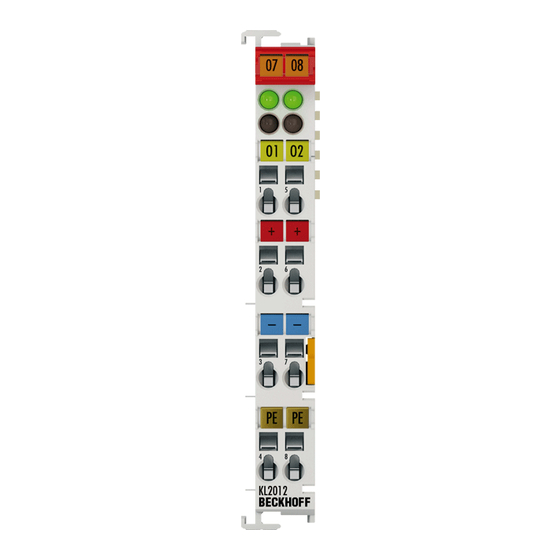
Page 11: Kl2012 - Leds And Connection
Product overview 2.2.2 KL2012 - LEDs and connection Fig. 4: KL2012 - LEDs and connection KL2012 - LEDs Color Meaning Signal LEDs 1 - 2 green Signal voltage "0" Signal voltage "1" KL2012 - Connection Terminal point Description Name Output 1 Output 1 +24 V +24 V (internally connected to terminal point 6 and positive power contact) 0 V... -
Page 12: Kl2022 - Leds And Connection
Product overview 2.2.3 KL2022 - LEDs and connection Fig. 5: KL2022 - LEDs and connection KL2022 - LEDs Color Meaning Signal LEDs 1 - 2 green Signal voltage "0" Signal voltage "1" KL2022 - Connection Terminal point Description Name Output 1 Output 1 +24 V +24 V (internally connected to terminal point 6 and positive power contact) 0 V... -
Page 13: Kl2032 - Leds And Connection
Product overview 2.2.4 KL2032 - LEDs and connection Fig. 6: KL2032 - LEDs and connection KL2032 - LEDs Color Meaning Signal LEDs 1 - 2 green Signal voltage "0" Signal voltage "1" KL2032 - Connection Terminal point Description Name Output 1 Output 1 +24 V +24 V (internally connected to terminal point 6 and positive power contact) 0 V... -
Page 14: Kl2114, Kl2134 - Introduction
Product overview KL2114, KL2134 - Introduction Fig. 7: KL2114 – 4-channel digital output terminal, 24 V , 0.5 A Fig. 8: KL2134 – 4-channel digital output terminal, 24 V , 0.5 A, protected against reverse polarity connection Version: 3.0.0 KL2xxx and KS2xxx... -
Page 15: Kl2114, Kl2134 - Technical Data
Product overview Four-channel, digital output terminal, 24 V The KL2114 and KL2134 digital output terminals connect the binary control signals from the automation unit on to the actuators at the process level with electrical isolation. The load current output of the KL2114 version is protected against overload and short circuit. -
Page 16: Kl2114 - Leds And Connection
Product overview 2.3.2 KL2114 - LEDs and connection Fig. 9: KL2114 - LEDs and connection KL2114 – LEDs Color Meaning Signal LEDs 1 - 4 green Signal voltage "0" Signal voltage "1" KL2114 - Connection Terminal point Description Name Output 1 Output 1 +24 V +24 V (internally connected to terminal point 6 and positive power contact) 0 V... -
Page 17: Kl2134 - Leds And Connection
Product overview 2.3.3 KL2134 - LEDs and connection Fig. 10: KL2134 - LEDs and connection KL2134 - LEDs Color Meaning Signal LEDs 1 - 4 green Signal voltage "0" Signal voltage "1" KL2134 - Connection Terminal point Description Name Output 1 Output 1 +24 V +24 V (internally connected to terminal point 6 and positive power contact) 0 V... -
Page 18: Kl2404, Kl2424 - Introduction
Product overview KL2404, KL2424 - Introduction Fig. 11: KL2404 – 4-channel digital output terminal, 24 V , 0.5 A Fig. 12: KL2404 – 4-channel digital output terminal, 24 V , 2 A Version: 3.0.0 KL2xxx and KS2xxx... -
Page 19: Kl2404, Kl2424 - Technical Data
Product overview 4-channel, digital output terminal, 24 V The KL2404 and KL2424 digital output terminals connect the binary 24 V control signals electrically isolated with the actuators. The Bus Terminals each contain four channels, whose signal states are displayed by LEDs. The variants KL2404 and KL2424 have different maximum output currents. The 4-channel Bus Terminals enable the direct connection of four 2-wire sensors. -
Page 20: Kl2404 - Leds And Connection
Product overview 2.4.2 KL2404 - LEDs and connection Fig. 13: KL2404 - LEDs and connection KL2404 - LEDs Color Meaning Signal LEDs 1 - 4 green Signal voltage "0" Signal voltage "1" KL2404 - Connection Terminal point Description Name Output 1 Output 1 0 V Ground for output 1 (internally connected to terminal point 3, 6, 7 and negative power contact) -
Page 21: Kl2424 - Leds And Connection
Product overview 2.4.3 KL2424 - LEDs and connection Fig. 14: KL2424 - LEDs and connection KL2424 - LEDs Color Meaning Signal LEDs 1 - 4 green Signal voltage "0" Signal voltage "1" KL2424 - Connection Terminal point Description Name Output 1 Output 1 0 V Ground for output 1 (internally connected to terminal point 3, 6, 7 and negative power contact) -
Page 22: Kl2408, Kl2488 - Introduction
Product overview KL2408, KL2488 - Introduction Fig. 15: KL2408 – 8-channel digital output terminal, 24 V , 0.5 A Fig. 16: KL2488 – 8-channel digital output terminal, 24 V , 0.5 A, ground switching Version: 3.0.0 KL2xxx and KS2xxx... -
Page 23: Kl2408, Kl2488 - Technical Data
Product overview Eight-channel, digital output terminal, 24 V The KL2408 (positive switching) and KL2488 (negative switching) digital output terminals connect the binary control signals from the automation unit on to the actuators at the process level with electrical isolation. The KL2408/KL2488 variants are protected against reverse polarity connection. They handle load currents with outputs that are protected against overload and short circuit. -
Page 24: Kl2408 - Leds And Connection
Product overview 2.5.2 KL2408 - LEDs and connection Fig. 17: KL2408 – 8-channel digital output terminal, 24 V , 0.5 A KL2408 - LEDs Color Meaning Signal LED 1 - 8 green Signal voltage "0" Signal voltage "1" KL2408 - Connection Terminal point Description Name... -
Page 25: Kl2488 - Leds And Connection
Product overview 2.5.3 KL2488 - LEDs and connection Fig. 18: KL2488 – 8-channel digital output terminal, 24 VDC, 0.5 A, ground switching KL2488 - LEDs Color Meaning Signal LED 1 - 8 green Signal voltage "0" Signal voltage "1" KL2488 - Connection Terminal point Description Name... -
Page 26: Mounting And Wiring
Mounting and wiring Mounting and wiring Installation on mounting rails WARNING Risk of electric shock and damage of device! Bring the bus terminal system into a safe, powered down state before starting installation, disassembly or wiring of the bus terminals! Assembly Fig. 19: Attaching on mounting rail The bus coupler and bus terminals are attached to commercially available 35 mm mounting rails (DIN rails... -
Page 27: Fig. 20 Disassembling Of Terminal
Mounting and wiring Disassembly Fig. 20: Disassembling of terminal Each terminal is secured by a lock on the mounting rail, which must be released for disassembly: 1. Pull the terminal by its orange-colored lugs approximately 1 cm away from the mounting rail. In doing so for this terminal the mounting rail lock is released automatically and you can pull the terminal out of the bus terminal block easily without excessive force. -
Page 28: Fig. 21 Power Contact On Left Side
Mounting and wiring Fig. 21: Power contact on left side NOTE Possible damage of the device Note that, for reasons of electromagnetic compatibility, the PE contacts are capacitatively coupled to the mounting rail. This may lead to incorrect results during insulation testing or to damage on the terminal (e.g. disruptive discharge to the PE line during insulation testing of a consumer with a nominal voltage of 230 V). -
Page 29: Installation Instructions For Enhanced Mechanical Load Capacity
Mounting and wiring Installation instructions for enhanced mechanical load capacity WARNING Risk of injury through electric shock and damage to the device! Bring the Bus Terminal system into a safe, de-energized state before starting mounting, disassembly or wiring of the Bus Terminals! Additional checks The terminals have undergone the following additional tests: Verification Explanation... -
Page 30: Fig. 22 Standard Wiring
Mounting and wiring Standard wiring Fig. 22: Standard wiring The terminals of KLxxxx and ELxxxx series have been tried and tested for years. They feature integrated screwless spring force technology for fast and simple assembly. Pluggable wiring Fig. 23: Pluggable wiring The terminals of KSxxxx and ESxxxx series feature a pluggable connection level. The assembly and wiring procedure for the KS series is the same as for the KLxxxx and ELxxxx series. -
Page 31: Fig. 25 Mounting A Cable On A Terminal Connection
Mounting and wiring Wiring HD Terminals The High Density Terminals of the KLx8xx and ELx8xx series doesn't support steady wiring. Ultrasonically "bonded" (ultrasonically welded) conductors Ultrasonically “bonded” conductors It is also possible to connect the Standard and High Density terminals with ultrasonically “bonded”... - Page 32 Mounting and wiring Terminal housing High Density Housing Wire size width (conductors with a wire end sleeve) 0.14 ... 0.75 mm Wire size width (single core wires) 0.08 ... 1.5 mm Wire size width (fine-wire conductors) 0.25 ... 1.5 mm Wire size width (ultrasonically “bonded" conductors) only 1.5 mm (see notice [} 31]!) Wire stripping length...
-
Page 33: Atex - Special Conditions (Extended Temperature Range)
80°C at the wire branching points, then cables must be selected whose tempera- ture data correspond to the actual measured temperature values! • Observe the permissible ambient temperature range of -25 to 60°C for the use of Beckhoff fieldbus com- ponents with extended temperature range (ET) in potentially explosive areas! •... -
Page 34: Continuative Documentation About Explosion Protection
Explosion protection for terminal systems Pay also attention to the continuative documentation Notes on the use of the Beckhoff terminal systems in hazardous areas according to ATEX and IECEx that is available for download on the Beckhoff homepage https:\\www.beckhoff.com! Version: 3.0.0... -
Page 35: Twincat
The general use of hardware and software from the open PC world requires some checking: Unsuitable components can upset the PC system. Beckhoff integrates a handy display of the real-time jitter in order to provide administrators with a simple means of evaluating hardware and software. A system message during operation can draw attention to error states. -
Page 36: Programming
According to the requirement for operating resources, the TwinCAT software devices can be distributed: TwinCAT PLC programs can be executed on PCs and on Beckhoff Bus Terminal controllers. A "message router" manages and distributes all the messages, both in the system and via TCP/IP connections. PC systems can be connected to one another by TCP/IP;... -
Page 37: Appendix
Beckhoff's branch offices and representatives Please contact your Beckhoff branch office or representative for local support and service on Beckhoff products! The addresses of Beckhoff's branch offices and representatives round the world can be found on her internet pages: http://www.beckhoff.com You will also find further documentation for Beckhoff components there. - Page 38 List of illustrations List of illustrations Fig. 1 KL2012 – 2-channel digital output terminal, 24 VDC, 0.5 A ............Fig. 2 KL2022 – 2-channel digital output terminal, 24 VDC, 2 A ............Fig. 3 KL2032 – 2-channel digital output terminal, 24 VDC, 0.5 A, protected against reverse polarity connection ...........................
- Page 40 More Information: www.beckhoff.de/default.asp?bus_terminal/digout.htm Beckhoff Automation GmbH & Co. KG Hülshorstweg 20 33415 Verl Germany Phone: +49 5246 9630 info@beckhoff.com www.beckhoff.com...
Need help?
Do you have a question about the KL2 Series and is the answer not in the manual?
Questions and answers