
Subscribe to Our Youtube Channel
Related Manuals for Beckhoff KL31 2 Series


Summary of Contents for Beckhoff KL31 2 Series
- Page 1 Documentation KL31x2 Two Channel Accurate Analog Terminals Version: 2.4.0 Date: 2019-02-11...
-
Page 3: Table Of Contents
Table of contents Table of contents 1 Foreword .............................. 5 Notes on the documentation...................... 5 Safety instructions .......................... 6 Documentation issue status ...................... 7 2 Product overview............................ 9 KL3132, KL3162, KL3172, KL3182 .................... 9 2.1.1 Introduction ........................ 9 2.1.2 Technical data ......................... 10 KL3142, KL3152 .......................... 11 2.2.1 Introduction ........................ - Page 4 Table of contents Version: 2.4.0 KL31x2...
-
Page 5: Foreword
The TwinCAT Technology is covered, including but not limited to the following patent applications and patents: EP0851348, US6167425 with corresponding applications or registrations in various other countries. ® EtherCAT is registered trademark and patented technology, licensed by Beckhoff Automation GmbH, Germany. Copyright © Beckhoff Automation GmbH & Co. KG, Germany. -
Page 6: Safety Instructions
All the components are supplied in particular hardware and software configurations appropriate for the application. Modifications to hardware or software configurations other than those described in the documentation are not permitted, and nullify the liability of Beckhoff Automation GmbH & Co. KG. Personnel qualification This description is only intended for trained specialists in control, automation and drive engineering who are familiar with the applicable national standards. -
Page 7: Documentation Issue Status
Foreword Documentation issue status Version Comment 2.4.0 • Note on differential measurement added 2.3.0 • Example program added to chapter “KS2000 Configuration software“ 2.2.0 • Update section “Technical data” (voltage measurement terminals only) 2.1.0 • Update section “Basic function principles” 2.0.0 •... - Page 8 Foreword WW - week of production (calendar week) YY - year of production FF - firmware version HH - hardware version Example with ser. no.: 35 04 1B 01: 35 - week of production 35 4 - year of production 2004 1B - firmware version 1B 1 - hardware version 1 Version: 2.4.0...
-
Page 9: Product Overview
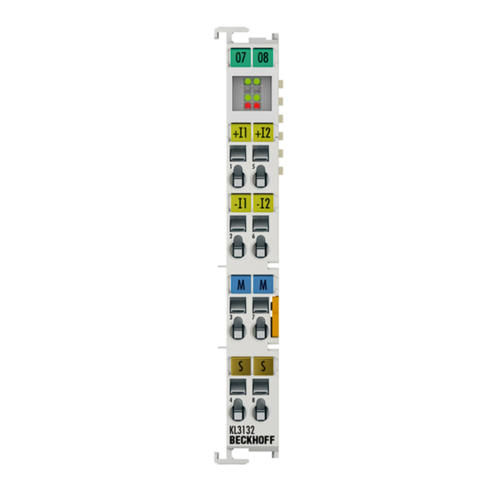
Product overview Product overview KL3132, KL3162, KL3172, KL3182 2.1.1 Introduction Fig. 1: KL3132 Two-channel analog terminals with voltage inputs (0.05% accuracy) The analog input terminals KL3132, KL3162, KL3172 and KL3182 process signals in the range -10 V to +10 V. The voltage is digitized to a resolution of 16 bits, and is transmitted, electrically isolated, to the higher- level automation device. -
Page 10: Technical Data
Product overview 2.1.2 Technical data Technical data KL3132-0000, KL3162-0000, KL3172-0000, KL3172-0500, KL3172-1000, KL3182-0000, KS3132-0000 KS3162-0000 KS3172-0000 KS3172-0500 KS3172-1000 KS3182-0000 Number of inputs Input signal -10 V ... +10 V 0 ... 10 V 0 ... 2 V 0 ... 500 mV 0 ... 1 V -2 V ... +2 V Input resistance > 70 kΩ... -
Page 11: Kl3142, Kl3152
Product overview KL3142, KL3152 2.2.1 Introduction Fig. 2: KL3142 Two-channel analog terminals with current inputs (0.05% accuracy) The KL3142 and KL3152 analog input terminals handle signals in the range between 0 and 20 mA, and between 4 and 20 mA respectively. The current is digitized to a resolution of 16 bits (default: 15 bits), and is transmitted, in an electrically isolated form, to the higher-level automation device. -
Page 12: Technical Data
Product overview 2.2.2 Technical data Technical data KL3142-0000, KS3142-0000 KL3152-0000, KS3152-0000 Number of inputs Signal current 0 ... 20 mA 4 ... 20 mA Internal resistance 100 Ω measuring resistance Common-mode voltage U ±10 V Resolution 16 bit Conversion time 140 ms, configurable Measuring error (full measuring range) ±0.05% of the full scale value, self-calibration Bit width in the K-Bus I/O 2 x 16 bit user data (optionally 2 x 8 bit control/status) -
Page 13: Basic Function Principles
Product overview Basic function principles The high-precision KL3172 analog input terminals can measure two voltages (KL3132, KL3162, KL3172, KL3182) or two currents (KL3142, KL3152) and display them with a resolution of 16 bits (65535 steps). High- precision measurements are ensured through cyclic self-calibration. By default, the inputs are switched as differential inputs. - Page 14 Product overview Name Name Unit Register Output value of the A/D converter Process data for controller Vendor calibration: Offset (can be disabled via bit R32.5 [} 49] of the R17 [} 47] feature register) Vendor calibration: Gain (always active) [1 x 2 + 1] R18 [} 47] Calibration: Offset (can be enabled via bit R32.5 [} 49] of the feature R1 [} 46]...
- Page 15 Product overview • In the first phase of the calibration, an input voltage of 0 V is applied to both analog inputs (zero calibration). The zero points of both analog input stages can be determined in this way. For this measurement, the respective absolute value of the channels is of interest. The value is subsequently stored in the RAM (register R1 [} 46]).
-
Page 16: Fig. 3 Differential Measuring
Product overview Fig. 3: Differential measuring Version: 2.4.0 KL31x2... -
Page 17: Leds
Product overview LEDs Fig. 4: LEDs Display K-bus power Power supply (5 V) available on the K-bus (green) OFF No power supply (5 V) available on the K-bus K-Bus Run Data transmission on the K-bus is active (green) OFF Data transmission on the K-bus is not active Run 1 Channel 1 active: (green) -
Page 18: Fitting And Wiring
Fitting and wiring Fitting and wiring Installation on mounting rails WARNING Risk of electric shock and damage of device! Bring the bus terminal system into a safe, powered down state before starting installation, disassembly or wiring of the bus terminals! Assembly Fig. 5: Attaching on mounting rail The bus coupler and bus terminals are attached to commercially available 35 mm mounting rails (DIN rails... -
Page 19: Fig. 6 Disassembling Of Terminal
Fitting and wiring Disassembly Fig. 6: Disassembling of terminal Each terminal is secured by a lock on the mounting rail, which must be released for disassembly: 1. Pull the terminal by its orange-colored lugs approximately 1 cm away from the mounting rail. In doing so for this terminal the mounting rail lock is released automatically and you can pull the terminal out of the bus terminal block easily without excessive force. -
Page 20: Connection
Fitting and wiring Fig. 7: Power contact on left side NOTE Possible damage of the device Note that, for reasons of electromagnetic compatibility, the PE contacts are capacitatively coupled to the mounting rail. This may lead to incorrect results during insulation testing or to damage on the terminal (e.g. disruptive discharge to the PE line during insulation testing of a consumer with a nominal voltage of 230 V). -
Page 21: Fig. 8 Standard Wiring
Fitting and wiring Standard wiring (ELxxxx / KLxxxx) Fig. 8: Standard wiring The terminals of ELxxxx and KLxxxx series have been tried and tested for years. They feature integrated screwless spring force technology for fast and simple assembly. Pluggable wiring (ESxxxx / KSxxxx) Fig. 9: Pluggable wiring The terminals of ESxxxx and KSxxxx series feature a pluggable connection level. -
Page 22: Wiring
Fitting and wiring Wiring HD Terminals The High Density (HD) Terminals of the ELx8xx and KLx8xx series doesn't support pluggable wiring. Ultrasonically "bonded" (ultrasonically welded) conductors Ultrasonically “bonded" conductors It is also possible to connect the Standard and High Density Terminals with ultrasonically "bonded"... -
Page 23: Shielding
Fitting and wiring Terminal housing ELxxxx, KLxxxx ESxxxx, KSxxxx Wire size width (single core wires) 0.08 ... 2.5 mm 0.08 ... 2.5 mm Wire size width (fine-wire conductors) 0.08 ... 2.5 mm 0,08 ... 2.5 mm Wire size width (conductors with a wire end sleeve) 0.14 ... -
Page 24: Pin Assignment
Fitting and wiring 3.2.4 Pin assignment WARNING Risk of injury through electric shock and damage to the device! Bring the Bus Terminals system into a safe, de-energized state before starting mounting, disassembly or wiring of the Bus Terminals! Fig. 12: KL3132 - pin assignment Fig. 13: KL3142 - pin assignment Version: 2.4.0 KL31x2... - Page 25 Fitting and wiring Terminal point No. Connection for Input 1+ + input channel 1 Input 1- - input channel 1 Internal ground (internally connected to terminal point 7) Shield PE contact (internally connected to terminal point 8) Input 2+ + input channel 2 Input 2- - input channel 2 Internal ground (internally connected to terminal point 3)
-
Page 26: Atex - Special Conditions (Standard Temperature Range)
80°C at the wire branching points, then cables must be selected whose tempera- ture data correspond to the actual measured temperature values! • Observe the permissible ambient temperature range of 0 to 55°C for the use of Beckhoff fieldbus compo- nents standard temperature range in potentially explosive areas! •... -
Page 27: Atex Documentation
Notes about operation of the Beckhoff terminal systems in potentially explosive ar- eas (ATEX) Pay also attention to the continuative documentation Notes about operation of the Beckhoff terminal systems in potentially explosive areas (ATEX) that is available in the download area of the Beckhoff homepage http:\\www.beckhoff.com! KL31x2... -
Page 28: Application Example For Kl3172-0000
Fitting and wiring Application example for KL3172-0000 WARNING Risk of injury through electric shock and damage to the device! Bring the Bus Terminals system into a safe, de-energized state before starting mounting, disassembly or wiring of the Bus Terminals! Monitoring the cell voltages of a battery with several KL3172. Fig. 14: KL3172-0000 - application example NOTE Do not exceed the dielectric strength! -
Page 29: Configuration Software Ks2000
Configuration Software KS2000 Configuration Software KS2000 KS2000 - Introduction The KS2000 configuration software permits configuration, commissioning and parameterization of bus couplers, of the affiliated bus terminals and of Fieldbus Box Modules. The connection between bus coupler / Fieldbus Box Module and the PC is established by means of the serial configuration cable or the fieldbus. Fig. 15: KS2000 configuration software Configuration You can configure the Fieldbus stations with the Configuration Software KS2000 offline. - Page 30 Configuration Software KS2000 Commissioning The KS2000 software facilitates commissioning of machine components or their fieldbus stations: Configured settings can be transferred to the fieldbus modules by means of a download. After a login to the terminal station, it is possible to define settings in couplers, terminals and Fieldbus Box modules directly online. The same high-level dialogs and register access are available for this purpose as in the configuration phase.
-
Page 31: Parameterization With Ks2000
Configuration Software KS2000 Parameterization with KS2000 Connect the configuration interface of your fieldbus coupler with the serial interface of your PC via the configuration cable and start the KS2000 Configuration Software. Click on the Login button. The configuration software will now load the information for the connected fieldbus station. -
Page 32: Fig. 17 Ks2000 Branch For Channel 1 Of The Kl3172
Configuration Software KS2000 Fig. 17: KS2000 branch for channel 1 of the KL3172 For the KL3172, the branches Register, Settings and ProcData are displayed: • Register [} 33] enables direct access to the KL3172 registers. • A dialog mask for the parameterization of the KL3172 can be found under Settings [} 34]. •... -
Page 33: Register
Configuration Software KS2000 Register You can access the registers of the KL3172 directly under Register. The meaning of the register is explained in the register overview [} 45]. Fig. 18: Register view in KS2000 KL31x2 Version: 2.4.0... -
Page 34: Settings
Configuration Software KS2000 Settings The dialog mask for the parameterization of the KL3172 can be found under Settings. Fig. 19: Settings via KS2000 Operation mode Channel disabled (R32.11 [} 49]) Here you can disable this channel, in order facilitate a faster cycle time for the other channel (default: not disabled). - Page 35 Configuration Software KS2000 Siemens output format (R32.4 [} 49]) You can activate Siemens output format here (default: deactivated). Calibration active (R32.5 [} 49]) You can deactivate the calibration here (default: activated). Differential measurement (R32.6 [} 49]) You can deactivate the differential measurement here (default: activated). Stabilization of calibration active (R32.7 [} 49]) You can deactivate the stabilization of the calibration here (default: activated).
-
Page 36: Sample Program For Kl Register Communication Via Ethercat On Kl3314 Exemplary
Configuration Software KS2000 Limit value 2 (R36 [} 50]) You can specify the limit value 2 here (default: 0). Filter constant (R37.11-R37.4 [} 50]) The filter constant SF specifies the 3dB limit frequency of the sinc filter (default: 860 (TM) Fast-Step Mode enabled (R37.0 [} 50]) You can activate Fast Step Mode here (default: deactivated). -
Page 37: Fig. 20 Settings Of Kl3314 Via Visualisation Of Twincat 3
[coupler (e.g. BK1120) or embedded PC] + KL3314 + KL9010. Download: https://infosys.beckhoff.com/content/1033/kl31x2/Resources/zip/5996114571.zip Preparations for starting the sample programs (tnzip file / TwinCAT 3) • Click on the download button to save the Zip archive locally on your hard disk, then unzip the *.tnzip archive file in a temporary folder. -
Page 38: Fig. 22 Search Of The Existing Hw Configuration For The Ethercat Configuration Of The Example
Configuration Software KS2000 • Select the .tnzip file (sample program). • A further selection window opens. Select the destination directory for storing the project. • For a description of the general PLC commissioning procedure and starting the program please refer to the terminal documentation or the EtherCAT system documentation. -
Page 39: Access From The User Program
Access from the user program Access from the user program Process image The terminals KL3132, KL3162, KL3142, KL3152 KL3172 and KL3148 are represented in the process image with a maximum of 6 bytes of input data and 6 bytes of output data. These are organized as follows: Format Input data Output data... -
Page 40: Mapping
Access from the user program KL3172-0000 Voltage Decimal Hexadecimal 0 V 0x0000 2 V 65535 0xFFFF KL3172-0500 Voltage Decimal Hexadecimal 0 V 0x0000 500 mV 65535 0xFFFF KL3172-1000 Voltage Decimal Hexadecimal 0 V 0x0000 1 V 65535 0xFFFF KL3182-0000 Voltage Decimal Hexadecimal -2 V -32768 0x8000 +2 V +32767 0x7FFF Mapping... - Page 41 Access from the user program Address Input data Output data Requirements Word offset High byte Low byte High byte Low byte Complete evaluation: no Ch1 D1 Ch1 D0 Motorola format: no Ch2 D1 Ch2 D0 Word alignment: any Compact evaluation in Motorola format Default mapping for PROFIBUS and Interbus coupler Address Input data...
-
Page 42: Control And Status Byte
Access from the user program Complete evaluation: In addition to the process data, the control and status bytes are also mapped into the address space. Motorola format: Motorola or Intel format can be set. Word alignment: In order for the channel address range to commence at a word boundary, empty bytes are inserted into the process image as appropriate. - Page 43 Access from the user program Name Description SB1.7 RegAccess Acknowledgment for process data mode SB1.6 Error no error detected KL3142 up to firmware 2B • Overload (bit SB1.1 [} 42] is set) or KL3142 with firmware 2C or higher and R32.14 [} 49] = 1 •...
- Page 44 Access from the user program Status byte 1 (in register communication) The status byte 1 (SB1) is located in the input image [} 39] and is transmitted from terminal to the controller. SB1.7 SB1.6 SB1.5 SB1.4 SB1.3 SB1.2 SB1.1 SB1.0 Name RegAccess R/W Reg.
-
Page 45: Register Overview
Access from the user program Register overview The registers are used for the parameterization of the Bus Terminals and are available for each channel. They can be read or written by means of register communication [} 43]. Register no. Comment Default value Memory Raw ADC value 0x0000... -
Page 46: Register Description
Access from the user program Register no. Comment Default value Memory User offset 0x0000 SEEPROM R33 [} 50] User gain 0x0100 SEEPROM R34 [} 50] Limit value 1 0x0000 SEEPROM R35 [} 50] Limit value 2 0x0000 SEEPROM R36 [} 50] Filter constants of the A/D converter, and configuration bits 0x35C0 13760 SEEPROM... - Page 47 Access from the user program Command 0x7000: Restore Factory Settings Entering 0x7000 in register R7 restores the factory settings for the following registers of both channels: KL3162, KL3172, KL3142, KL3152: KL3132, KL3182: R32: 0x0180 (384 R32: 0x0182 (386 R33: 0x0000 (0 R33: 0x0000 (0 R34: 0x0100 (256 R34: 0x0100 (256 R35: 0x0000 (0...
- Page 48 Access from the user program R19: Manufacturer scaling - offset: This register contains the offset of the manufacturer scaling. Can be activated via R32.1 [} 49] in the feature register (16 bit signed integer). R20: Manufacturer scaling - gain: This register contains the gain of the manufacturer scaling. Can be activated via R32.1 [} 49] in the feature register (16 bit unsigned integer x 2- + 1).
- Page 49 Access from the user program Name Description default R32.15* CallibrationDisplay During the calibration, the terminal sets the overload bit SB1.1 [} 42] and the underload bit SB1.0 [} 42]. Compatibility mode: During calibration, the terminal sets the error bit SB1.6 [} 42]. R32.14* Display StabilityError 0 Stability error is not displayed.
- Page 50 Access from the user program For lower firmware versions, bits R32.14 and R32.15 are not evaluated. These terminals always set the error bit SB1.6 [} 42] during the calibration and cannot indicate the stability error! R33: User scaling - offset This register contains the offset of the user scaling. The user scaling can be activated in the feature register through bit R32.0 [} 49] (16 bit signed integer).
- Page 51 Access from the user program Name Description Default R37.1 SkipFIR FIR filter is active. FIR filter is bypassed. R37.0 Fast Fast Step Mode is not active. Fast Step Mode is active: a fast reaction will follow jumps at the input, in spite of the filter stage being active. In this case the filter is bypassed! Examples Value in R37...
-
Page 52: Examples Of Register Communication
Access from the user program Examples of Register Communication The numbering of the bytes in the examples corresponds to the display without word alignment. 5.6.1 Example 1: reading the firmware version from Register 9 Output Data Byte 0: Control byte Byte 1: DataOUT1, high byte Byte 2: DataOUT1, low byte 0x89 (1000 1001... - Page 53 Access from the user program Input Data (answer of the bus terminal) Byte 0: Status byte Byte 1: DataIN1, high byte Byte 2: DataIN1, low byte 0x9F (1001 1111 0xXX 0xXX Explanation: • The terminal returns a value as a receipt in the status byte that differs only in bit 0.6 from the value of the control byte.
- Page 54 Access from the user program Input data (response from the Bus Terminal) Byte 0: Status byte Byte 1: DataIN1, high byte Byte 2: DataIN1, low byte 0xA0 (1010 0000 0xXX 0xXX Explanation: • The terminal returns a value as a receipt in the status byte that differs only in bit 0.6 from the value of the control byte.
-
Page 55: Appendix
Beckhoff's branch offices and representatives Please contact your Beckhoff branch office or representative for local support and service on Beckhoff products! The addresses of Beckhoff's branch offices and representatives round the world can be found on her internet pages: http://www.beckhoff.com You will also find further documentation for Beckhoff components there. - Page 56 List of illustrations List of illustrations Fig. 1 KL3132 ............................Fig. 2 KL3142 ............................Fig. 3 Differential measuring........................Fig. 4 LEDs ............................Fig. 5 Attaching on mounting rail ......................Fig. 6 Disassembling of terminal......................Fig. 7 Power contact on left side......................Fig.
Need help?
Do you have a question about the KL31 2 Series and is the answer not in the manual?
Questions and answers