
Related Manuals for Beckhoff KL17 Series


Summary of Contents for Beckhoff KL17 Series
- Page 1 Documentation | EN KL17xx/KS17xx Digital input terminals 2021-08-04 | Version: 4.1.0...
-
Page 3: Table Of Contents
Table of contents Table of contents 1 Foreword .............................. 5 Notes on the documentation...................... 5 Safety instructions .......................... 6 Documentation issue status ...................... 7 2 Product overview............................ 8 KL/KS1702, KL/KS1712 - Introduction .................... 8 2.1.1 Technical data ........................ 9 2.1.2 Contact assignment and LEDs .................. 10 KL/KS1704 - Introduction ........................ 11 2.2.1 Technical data ......................... - Page 4 Table of contents Version: 4.1.0 KL17xx/KS17xx...
-
Page 5: Foreword
, XTS and XPlanar are registered trademarks of and licensed by Beckhoff Automation GmbH. Other designations used in this publication may be trademarks whose use by third parties for their own purposes could violate the rights of the owners. Patent Pending... -
Page 6: Safety Instructions
All the components are supplied in particular hardware and software configurations appropriate for the application. Modifications to hardware or software configurations other than those described in the documentation are not permitted, and nullify the liability of Beckhoff Automation GmbH & Co. KG. Personnel qualification This description is only intended for trained specialists in control, automation and drive engineering who are familiar with the applicable national standards. -
Page 7: Documentation Issue Status
Foreword Documentation issue status Version Comment 4.1.0 • Product overview extended • Technical data updated • Ex markings added to technical data • Instructions for ESD protection added • Chapter Disposal added • New title page 4.0.0 • Migration • Document structure updated •... -
Page 8: Product Overview
Product overview Product overview Digital input terminals Terminal Number of inputs Nominal voltage Filter Comment 120 V / 230 V 10 ms KL/KS1702 [} 8] 120 V / 230 V 10 ms KL/KS1704 [} 11] 120 V 10 ms KL/KS1712-0000 [} 8] AC/DC 24 V 10 ms KL/KS1712-0010 [} 8] AC/DC 60 V 10 ms KL/KS1712-0060 [} 8] 120 V / 230 V 10 ms... -
Page 9: Technical Data
Product overview 2.1.1 Technical data Technical data KL1702-0000, KL1712-0000, KL1712-0010, KL1712-0060, KS1702-0000 KS1712-0000 KS1712-0010 KS1712-0060 Number of inputs Connection technology 4-wire Nominal voltage 120 V /230 V 120 V 24 V 60 V AC/DC AC/DC Signal voltage "0" 0 V … 40 V 0 V … 5 V 0 V … 20 V Signal voltage "1"... -
Page 10: Contact Assignment And Leds
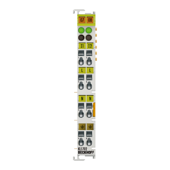
Product overview 2.1.2 Contact assignment and LEDs Fig. 2: KL1702 - Contact assignment and LEDs KL1702/KS1702, KL1712/KS1712 - Contact assignment Terminal point Description Name Input 1 Input 1 Mains voltage Sensor supply (from power contact) 0 V Sensor supply (from power contact) PE (from power contact) Input 2 Input 2 Mains voltage... -
Page 11: Kl/Ks1704 - Introduction
Product overview KL/KS1704 - Introduction Fig. 3: KL1704 Four channel digital input terminal 120/230 V The KL/KS1704 digital input terminal acquires the binary control signals from the process level and transmits them, in an electrically isolated form, to the higher-level automation unit. The direct connection of 120/230 sensors is possible. -
Page 12: Technical Data
Product overview 2.2.1 Technical data Technical data KL1704, KS1704 Connection technology 2 wire Number of inputs Nominal voltage 120/230 V Signal voltage ‘0’ 0 V … 40 V Signal voltage ‘1’ 79 V … 260 V Input filter typ. 10 ms Input current 4.6 mA typ. at 230 V, 2.3 mA typ. at 120 V Current consumption from K-bus typ. -
Page 13: Contact Assignment And Leds
Product overview 2.2.2 Contact assignment and LEDs Fig. 4: KL1704/KS1704 - Contact assignment and LEDs KL1704/KS1704 - Contact assignment Terminal point Description Name Input 1 Input 1 +120 V/230 V Sensor supply (from power contact) +120 V/230 V Sensor supply (from power contact) Input 3 Input 3 Input 2 Input 2 +120 V/230 V... -
Page 14: Kl/Ks1722 - Introduction
Product overview KL/KS1722 - Introduction Fig. 5: KL1722 Two-channel digital input terminal 120/230 V The KL/KS1722 digital input terminal acquires the binary control signals from the process level and transmits them, in an electrically isolated form, to the higher-level automation unit. The direct connection of 120 V/230 V sensors is possible. -
Page 15: Technical Data
Product overview 2.3.1 Technical data Technical data KL1722, KS1722 Connection technology 2 wire Number of counters Nominal voltage 120/230 V Signal voltage ‘0’ 0 V … 40 V Signal voltage ‘1’ 79 V … 260 V Input filter typ. 10 ms Input current > 3 mA, typ. 6 mA Current consumption from K-bus typ. -
Page 16: Contact Assignment And Leds
Product overview 2.3.2 Contact assignment and LEDs Fig. 6: KL1722 - Contact assignment and LEDs KL1722/KS1722 - Contact assignment Terminal point Description Name Input 1 Input 1, neutral conductor, belonging to Input 1 Input 2 Input 2, neutral conductor, belonging to Input 2 KL1722/KS1722 - LED Displays Color Meaning Signal LEDs 1 - 2 green off Signal voltage "0"... -
Page 17: Mounting And Wiring
• Surroundings (working place, packaging and personnel) should by grounded probably, when handling with the devices. • Each assembly must be terminated at the right hand end with a KL9010 bus end terminal, to ensure the protection class and ESD protection. Fig. 7: Spring contacts of the Beckhoff I/O components KL17xx/KS17xx Version: 4.1.0... -
Page 18: Installation On Mounting Rails
Mounting and wiring Installation on mounting rails WARNING Risk of electric shock and damage of device! Bring the bus terminal system into a safe, powered down state before starting installation, disassembly or wiring of the bus terminals! Assembly Fig. 8: Attaching on mounting rail The bus coupler and bus terminals are attached to commercially available 35 mm mounting rails (DIN rails according to EN 60715) by applying slight pressure: 1. -
Page 19: Fig. 9 Disassembling Of Terminal
Mounting and wiring Disassembly Fig. 9: Disassembling of terminal Each terminal is secured by a lock on the mounting rail, which must be released for disassembly: 1. Pull the terminal by its orange-colored lugs approximately 1 cm away from the mounting rail. In doing so for this terminal the mounting rail lock is released automatically and you can pull the terminal out of the bus terminal block easily without excessive force. -
Page 20: Fig. 10 Power Contact On Left Side
Mounting and wiring Fig. 10: Power contact on left side NOTE Possible damage of the device Note that, for reasons of electromagnetic compatibility, the PE contacts are capacitatively coupled to the mounting rail. This may lead to incorrect results during insulation testing or to damage on the terminal (e.g. disruptive discharge to the PE line during insulation testing of a consumer with a nominal voltage of 230 V). -
Page 21: Installation Instructions For Enhanced Mechanical Load Capacity
Mounting and wiring Installation instructions for enhanced mechanical load capacity WARNING Risk of injury through electric shock and damage to the device! Bring the Bus Terminal system into a safe, de-energized state before starting mounting, disassembly or wiring of the Bus Terminals! Additional checks The terminals have undergone the following additional tests: Verification Explanation... -
Page 22: Connection
Mounting and wiring Connection 3.4.1 Connection system WARNING Risk of electric shock and damage of device! Bring the bus terminal system into a safe, powered down state before starting installation, disassembly or wiring of the bus terminals! Overview The bus terminal system offers different connection options for optimum adaptation to the respective application: •... -
Page 23: Fig. 13 High Density Terminals
Mounting and wiring A tab for strain relief of the cable simplifies assembly in many applications and prevents tangling of individual connection wires when the connector is removed. Conductor cross sections between 0.08 mm and 2.5 mm can continue to be used with the proven spring force technology. -
Page 24: Wiring
Mounting and wiring 3.4.2 Wiring WARNING Risk of electric shock and damage of device! Bring the bus terminal system into a safe, powered down state before starting installation, disassembly or wiring of the bus terminals! Terminals for standard wiring ELxxxx/KLxxxx and for pluggable wiring ESxxxx/KSxxxx Fig. 14: Connecting a cable on a terminal point Up to eight terminal points enable the connection of solid or finely stranded cables to the bus terminal. -
Page 25: Shielding
Mounting and wiring Terminal housing High Density Housing Wire size width (single core wires) 0.08 ... 1.5 mm Wire size width (fine-wire conductors) 0.25 ... 1.5 mm Wire size width (conductors with a wire end sleeve) 0.14 ... 0.75 mm Wire size width (ultrasonically “bonded" conductors) only 1.5 mm Wire stripping length 8 ... -
Page 26: Atex - Special Conditions (Standard Temperature Range)
80°C at the wire branching points, then cables must be selected whose tempera- ture data correspond to the actual measured temperature values! • Observe the permissible ambient temperature range of 0 to 55°C for the use of Beckhoff fieldbus compo- nents standard temperature range in potentially explosive areas! •... -
Page 27: Continuative Documentation For Atex And Iecex
IECEx Pay also attention to the continuative documentation Ex. Protection for Terminal Systems Notes on the use of the Beckhoff terminal systems in hazardous areas according to ATEX and IECEx that is available for download on the Beckhoff homepage www.beckhoff.com! -
Page 28: Twincat
The general use of hardware and software from the open PC world requires some checking: Unsuitable components can upset the PC system. Beckhoff integrates a handy display of the real-time jitter in order to provide administrators with a simple means of evaluating hardware and software. A system message during operation can draw attention to error states. - Page 29 According to the requirement for operating resources, the TwinCAT software devices can be distributed: TwinCAT PLC programs can be executed on PCs and on Beckhoff Bus Terminal controllers. A "message router" manages and distributes all the messages, both in the system and via TCP/IP connections. PC systems can be connected to one another by TCP/IP;...
-
Page 30: Programming
TwinCAT Programming TwinCAT libraries See software documentation in the Beckhoff Information System. TwinCAT 2: TwinCAT PLC Lib: I/O functions TwinCAT 3: TwinCAT 3 PLC Lib: Tc2_IoFunctions Version: 4.1.0 KL17xx/KS17xx... -
Page 31: Appendix
Please contact your Beckhoff branch office or representative for local support and service on Beckhoff products! The addresses of Beckhoff's branch offices and representatives round the world can be found on her internet pages: https://www.beckhoff.com You will also find further documentation for Beckhoff components there. - Page 32 KL1704/KS1704 - Contact assignment and LEDs............... Fig. 5 KL1722 ............................Fig. 6 KL1722 - Contact assignment and LEDs..................Fig. 7 Spring contacts of the Beckhoff I/O components................. Fig. 8 Attaching on mounting rail ......................Fig. 9 Disassembling of terminal......................Fig. 10 Power contact on left side......................
- Page 34 More Information: www.beckhoff.com/KL1xxx Beckhoff Automation GmbH & Co. KG Hülshorstweg 20 33415 Verl Germany Phone: +49 5246 9630 info@beckhoff.com www.beckhoff.com...
Need help?
Do you have a question about the KL17 Series and is the answer not in the manual?
Questions and answers