
Related Manuals for Mira Mode 1.1980.001


Summary of Contents for Mira Mode 1.1980.001
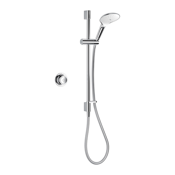
- Page 1 Mira Mode Digital Shower / Bathfiller 1479399 Installation and User Guide Please leave these instructions with the user...
-
Page 2: Table Of Contents
Thank you for purchasing a Mira Mode. You must read this guide thoroughly, and having done so, keep it handy for future reference. For step-by-step installation videos, datasheets or spares information, please visit the Mira Showers website. Contents Important Safety Information... -
Page 3: Important Safety Information
Important Safety Information Products manufactured by Kohler Mira Ltd. are designed to be safe, provided that they are installed, used and maintained in good working order, in accordance with our instructions and recommendations. Follow all warnings, cautions and instructions contained in this guide, and on, or inside the product. - Page 4 9. DO NOT perform any unspecified modifications, drill or cut holes in the product other than instructed by this guide. When servicing only use genuine Kohler Mira replacement parts. 10. If the product is dismantled during installation or servicing then, upon completion, an inspection must be made to ensure all electrical connections are secure and that there are no leaks.
- Page 5 19. The maximum mixed water temperature from the product is 48°C to take into account losses in metal baths. It is not a safe bathing or showering temperature. 20. Always check the water temperature is safe before bathing or showering. 21.
-
Page 6: Pack Contents
Pack Contents Digital Mixing Valve High Pressure/Combi 2 x Push-Fit Isolators 1 or 2 x Outlet Connector (Depending on number of outlets) Digital Mixing Valve 3 x Fixing Screws 3 x Wall Plugs 2 x Pozi Screws (3.5 x 12mm) 1 x Power Supply 2 x Fixing Feet Digital Mixing Valve Pumped/Gravity... - Page 7 Ceiling Fed Shower Fitting 1 x Plastic Pipe 1 x Ceiling Plate 2 x Spacers 1 x Slide Bar 1 x Elbow 1 x Handset 1 x Clamp Bracket 2 x Wall Plugs 2 x 45 mm Screws 1 x Extension 2 x 70 mm Screws 1 x Retaining Ring 2 x Brackets...
- Page 8 Rear Fed Shower Fitting 1 x Screw 1 x Cover Cap 1 x Slide Bar 1 x Fixing Supports Bracket 1 x Handset 1 x Hose 1 x Hex Key 2 x Rubber Washers 2.5mm 1 x Right Angled Connector 1 x Clamp Bracket 1 x Slide Bar...
- Page 9 Interface Important! Some parts may differ from the below depending on product purchased. 1 x Component Pack (Includes 1.5mm hex key) 1 x Backplate 1 x Interface 1 x Installation Template 1 x Coupler Cable 1 x Interface Lead...
- Page 10 1 x Elbow Dual Only 1 x Concealing Plate 1 x Ceiling Mount Plate Assembly 1 x Deluge Head Mira Maxim ONLY 1 x Chrome Supply Tube 1 x Deluge Head 1 x Rain Core 1 x Brazed Pipe Assembly...
- Page 11 2 x Wall Plugs Dual Only 2 x Fixing Screws 1 x Deluge Head 1 x Backplate Assembly Mira Maxim ONLY Bath Filler 1 x Filler 1 x Deluge Head 1 x Hose 1 x Rain Core 1 x Waste...
-
Page 12: Guarantee
The Mira Mode has been designed for domestic use only, it is not recommended for Commercial or Healthcare use. For domestic installations, Kohler Mira Ltd. guarantee the Mira Mode against any defect in materials or workmanship for a period of five years from the date of purchase (shower fittings for one year). -
Page 13: Specifications
Specifications Standards and Approvals The Mira Mode complies with all applicable UK & EU regulations & directives. The Mira Mode is a type 1 electronic, independently mounted control for surface mounting. Mira Mode is a thermostatic water mixing valve. The digital valve is equipped with Bluetooth wireless technology. - Page 14 All pressures refer to maintained pressure at valve inlets*. Mira Digital Mixing Valve Pumped/Gravity (not suitable for mains pressure systems) Caution! The pump in this product is not suitable for dry running. It is essential you follow the commissioning sequence detailed in this guide.
- Page 15 (pressure during product operation) at the valve inlets, you will not be able to achieve the maximum flow rate from your shower even if adjusted via the Mira Showers app. Please ensure you have the minimum required maintained pressure at the valve inlets before installation.
-
Page 16: Suitable Plumbing Installations
Suitable Plumbing Installations Digital Mixing Valve (High Pressure/Combi Models) 1. Combination boiler systems - the digital high pressure/combi shower can be installed with an instantaneous combination boiler. 2. Unvented mains pressurised system - the digital high pressure/combi shower can be installed with an unvented, stored hot water cylinder system. - Page 17 Digital Mixing Valve (Pumped/Gravity Models) Gravity fed hot water systems Caution! Digital pumped/gravity valves must never be plumbed to mains pressure systems. This includes mixed gravity fed and mains pressure e.g. gravity hot and mains cold. Doing so will invalidate the warranty and potentially cause product and property damage.
-
Page 18: Showering Maximum Flow Rate
The outlet flow rate can be altered by use of the Mira Showers app.* It may be necessary to alter the outlet flow rate using the Mira Showers app if your stored hot water is running out too quickly. -
Page 19: Installation Schematic
Installation Schematic Mira Mode Dual Ceiling Fed Shower Max. Cable length 9.8m Ceiling Fed Max. Cable length 9.8m Rear Fed Product Name Outlet 2 (left hand outlet) Outlet 1 (right hand outlet) Mira Mode Single Outlet Product Not Applicable Handset/Overhead/Bath filler... - Page 20 Mira Mode Dual Bath / Shower Max. Cable length 9.8m Rear Fed Product Name Outlet 2 (left hand outlet) Outlet 1 (right hand outlet) Mira Mode Dual Bath/Shower Bath filler Handset Product...
-
Page 21: General Installation
General Installation All installations shall comply with the Water Supply (Water Fittings) Regulations 1999, Water Supply (Water Fittings) Regulations (Northern Ireland) 2009, and The Water Supply (Water Fittings) (Scotland) Byelaws 2014. Safe and easy access to the product should be available at all times. When installing the product in an area not regularly accessed, consideration for potential leaks must be taken into account. -
Page 22: Installation Digital Mixing Valve
• To eliminate pipe debris it is essential that water supply pipes must be flushed prior to connecting the digital mixing valve to the system so debris cannot enter the digital mixing valve internals. • Fully commission the product after installation taking care to look for any leaks and correct operation. - Page 23 Fit the 2 feet in desired location on digital mixing valve using the two Torx 3.5 x 12mm screws supplied. Note: There are 4 possible locations to install the feet, depending on your installation constraints. Mark the fixing holes in the required positions and secure using suitable fixings. Note: The valve must be installed on a flat surface.
- Page 24 Connect the hot and cold inlet supply pipework to the digital mixing valve. Note: DO NOT use any type of jointing paste or compound on any pipework or fittings supplying the digital shower valve. These can build up within the product and reduce the performance or cause early failure.
- Page 25 Install the power supply unit provided, connecting it to the mains socket in accordance with the wiring regulations and permanently fix in place using suitable screws. Connect the power supply cable to the digital mixing valve and ensure it is firmly in place. Caution! Before any electrical adjustment is attempted, the electricity supply must be turned off at the mains switch.
-
Page 26: Ceiling Fed Shower Fittings
Installation: Ceiling Fed Shower Fittings Fix at convenient height for all the family. Position the fittings so that water sprays down the centre of the bath, or away from the opening of a shower cubicle. Water should spray away from the user controller when the handshower is held on the slide bar. Mark the positions of the fixing holes for the slide bar. - Page 27 Drill the fixing holes in the wall. Fit the wall plugs and the fixing brackets. Important! If supplied slide bar spacers are required, centre distance for ceiling hole will increase to 75 mm from wall. Use longer fixing screws if you are using the spacers.
- Page 28 Install the screws top and bottom to Install the falling supply tube. secure the slide bar in position using Note: The falling supply tube may a 3mm hex key. need to be shortened, use a hacksaw to shorten tube. Make sure the rough end is concealed in the ceiling.
- Page 29 Connect the shower control outlet pipework to the elbow. (Pipe and isolating valve not supplied). Elbow (supplied) a. Fit the shower hose to the end of the slide bar assembly. Ensure the washer is in place in both ends of the hose. Caution! DO NOT fit the handshower until after pipework has been fully flushed through.
-
Page 30: Ceiling Fed Deluge Head
Installation: Ceiling Fed Deluge Head Fix Deluge Head to the ceiling at a convenient height for all the family. Position so that water sprays down over the centre of the bath, or away from the opening of a shower cubicle. The fitting of the Deluge Head into the ceiling will be easier with two persons. - Page 31 Offer the ceiling-fed arm to the brass Secure the brass pipe to the ceiling pipe and determine the showering mount plate with the olive and 1/2” height required. Push or pull the brass BSP nut. pipe using a twisting motion to adjust Note: This is not a water tight the height.
- Page 32 Connect the elbow (supplied) onto the Connect the shower control outlet end of the brass pipe. Push all parts pipework to the elbow. (Pipes not together fully. supplied). Follow manufacturers guidelines for fitting flexible pipework. Elbow Ensure pipework is thoroughly flushed through before fitting the deluge head. Screw the fixed shower head onto the brass pipe outlet after commissioning has been completed.
-
Page 33: Rear Fed Shower Fittings
Installation: Rear Fed Shower Fittings Suitable for solid, dry-lined, stud partition, shower cubicle or laminated panel walls. Plan installation location of the handshower and deluge showerhead before installing fittings kit. Note: Make sure that the deluge head is not installed over the handshower. Fix at convenient height for all users. - Page 34 Mark the positions for the fixing holes Drill the fixing holes, fit the wall plugs for the right angled connector back and secure the backplate to the wall plate. with two fixing screws. 8 mm 8 mm DO NOT drill into buried cables.
- Page 35 Rotate the elbow to lock into position. Temporarily hold the top support in position. Make sure that it is level and mark through the position of the fixing hole in the top support. Optional hole Optional hole position(Only one position(Only one required) required) 621 mm to top...
- Page 36 Fit all the components onto the slide bar. Slide Bar Support Important! Press the buttons on the clamp bracket to slide it Clamp Bracket through the slide bar. Retaining Ring Fix the slide bar assembly in position, Carefully remove the slide bar making sure that it locates correctly.
- Page 37 Secure the assembly in position Fit the cap to the top of the slide bar with the screws using a 2.5mm and fit the hose to the bottom outlet. hex key. The top securing screw Make sure that you fit the washer tightens clockwise, the bottom into shower hose.
-
Page 38: Rear Fed Deluge Head
Installation: Rear Fed Deluge Head Fix at convenient height for all users. Position so that water sprays down the centre of the bath, or away from the opening of a shower cubicle. Make sure that the water sprays away from the interface and the showerhead. Note: Make sure that the deluge head is not installed over the handshower. - Page 39 Fit the concealing shroud, the Carefully fit the backplate over the compression nut and the olive onto outlet pipe and secure with the fixing the shower arm. screws (supplied). F i t t h e s h o w e r a r m i n t o t h e Caution! Take care not to damage compression nipple and tighten the the O Seal in the back of the...
-
Page 40: Bath Filler
Installation: Bath Filler Note: When the bath filler waste is extended, there may be a need to rotate the bodies to allow alignment to the mating surface. Refer below steps: • Loosen the jubilee clip at the overflow end. • Rotate the overflow body. Carefully follow the below assembly drawings Jubilee Clip to install the overflow bath filler and waste. - Page 41 Turn anti-clockwise to remove the water stopper then remove the installation tool, then reassemble the water stopper to the waste body without the installation tool. Note: An installation tool is supplied, this is stowed within the assembled waste body for packing purposes. Use this tool to screw the strainer into the waste body.
- Page 42 Push fit the water supply pipe to the bath filler using copper pipework (15mm diameter). Note: Make sure that the pipe is pushed in fully (min 30mm) until it hits the internal stop feature. Important! Cut the pipe using a pipe cutter only to ensure the seals are not damaged when the pipe is inserted.
-
Page 43: User Controller
Installation: User Controller Position the installation template (supplied) at the position on the wall where you intend to install the Controller. Make sure that the template is level and mark the positions of the fixing holes on the wall. For solid walls drill the fixing holes for the backplate with a 6mm drill and insert the wall plugs (supplied). - Page 44 Loosen the screw and remove the lid from the digital mixing valve using a pozi (PZ2) screwdriver. Connect the user coupler cable to digital mixing valve connection port 1 and route as shown. Connect the coupler cable to the 9.8m cable and route to the user controller location Connection Port 1 Coupler...
- Page 45 Fit the backplate to the wall in the orientation shown using the fixing screws (supplied). Tighten by hand, do not over tighten. Connect the cable on the back of the controller to the cable that comes from the valve. Locate the top of the controller in the backplate and press down on the bottom button as you install in position.
-
Page 46: Commissioning & Starting The Shower
Commissioning (High Pressure Product) WARNING! For the Pumped low pressure valve you must follow the separate valve commissioning sequence in the section below. Ensure all items on the below checklist have been ticked off prior to commissioning. This is a high pressure system product, DO NOT install on a gravity fed low pressure system. - Page 47 Turn on the electrical supply to digital mixing valve. The digital mixing valve will power and perform a self check where the LED will indicate a RED light initially and will then change to BLUE light after a few seconds. Note: If the LED does not turn to a solid BLUE light after 10 seconds, indicating the product is ready to use, refer to the troubleshooting or fault diagnosis section.
- Page 48 Press the button to turn the shower on and reduce temperature to full cold. Run cold water through (approximately 2 minutes) and check entire installation for water leaks. Press the Controller button to turn the shower off. Fit the second hose washer and handshower.
- Page 49 Commissioning (Pumped Product) WARNING: Silent pump cannot be dry run for extended period. Ensure all items on the below checklist have been ticked off prior to commissioning. This is a gravity system product, do not install on a mains pressure system. Ensure product is installed in a recommended orientation (as shown on page 22).
- Page 50 Turn on the electrical supply to digital mixing valve. The digital mixing valve will power and perform a self check where the LED will indicate a RED light initially and will then change to a BLUE/RED flashing light after a few seconds. Note: If the LED does not turn to a BLUE/RED flashing light after 10 seconds, indicating the product is ready to commission, refer to the troubleshooting or fault diagnosis section.
- Page 51 Indicate Flow. Wait for water to flow from the end of the hose or bath filler, then step on by pressing and holding the flashing button for 3 seconds. The product may step itself on if your water pressure is sufficient. 3 Seconds Pump Commissioning.
-
Page 52: Using The Shower
Using the Shower Note: The factory default maximum temperature is set to 45°C. Temperature Indicator On/Off Button Turns product On/Off. Rotary movement selects showering temperature Shower Overhead Symbol - (Top Button) – Turns Product Overhead On/Off. Shower Handset Symbol (Bottom Button) – Turns Product Handset On/Off. -
Page 53: Set Up: Controller
Set Up: Controller Maximum Temperature Setting with the User Interface Single Outlet Shower Hold down the On/Off Button for approximately 10 Seconds until the Temperature Indicator light pulses on/off. Note: After 5 seconds the lights will pulse to indicate pairing mode, you need to continue to hold the button for the entire 10 seconds. - Page 54 Dual Outlet Shower / Bathfill / Shower Bathfill H o l d d o w n t h e T o p b u t t o n f o r approximately 10 Seconds until the Temperature Indicator light pulses on/off.
-
Page 55: Bathfill Preset Adjustment
Bathfill Preset Adjustment For Products with a Bath Fill Shower Interface and Dual Shower/Bath fill Interface Bath Fill Preset – Push down the plug in the bath. Hold down the Bath Symbol Button (bottom half) for approximately 5 Seconds until the Bath Symbol Button flashes. Press the Bath Symbol Button (bottom half) to start the Bath filling. -
Page 56: User Interface Function Guide
Flashing 2x per second Wrong interface error Flashing 2x per second Comms error Flashing 2x per second Other Valve error Flashing 2x per second Both Valve and UI error Flashing 2x per second Accessories Product Product Code Mira Wireless Remote Accessory 2.1903.098... -
Page 57: Set Up: Mobile App
Please ensure your mobile device is configured for automatic app updates to ensure that the Mira Showers app is kept up to date with the latest bug fixes and performance enhancements. Once the Mira Showers app has been installed, open the app on your device and follow the on-screen instructions to connect your phone to your Digital Mixing Valve. -
Page 58: Fault Diagnosis
(2 times a second) Power off the product for 30 seconds or reset the product in the Mira Showers app. If the error re-appears, please contact Mira customer services team. - Page 59 (contact your installer). If no sign of leaks, reset the product by powering off for 30 seconds or re-setting in the Mira Showers app. Ensure there are no leaks when the shower is first used.
- Page 60 Unable to download Phone OS out of date. Update mobile phone to the latest operating the Mira Showers system. Note: The Mira Mode showering app will only run on the Mobile App latest Apple and Android Operating Systems. Repeated Mira App may be corrupted.
- Page 61 Check the circuit breaker or RCD in your consumer unit has not tripped. Check the fuse and replace if necessary (3 Amp). Contact Mira Customer Service Team if none of the above restored power to the digital mixing valve. Diagnosis stage 4 (Product powered, but no error code): If you have a problem with your shower but do not have an error code, find the relevant section and follow the recommendations before contacting Mira.
- Page 62 Reduce or increase the maximum flow rate to around 8 litres per minute using the Mira showers app and see if that solves the issue. Tip: Use the Mira Showers app to check the temperature of the hot water inlet when the shower is running.
- Page 63 The shower is designed to turn off after 30 minutes. Use the Mira Showers app to check the error log. The shower is designed to turn off if the outlet temperature is too high. Check inlet water temperature and pressures are within specification. The shower may turn off if these are out of specification.
-
Page 64: Cleaning & Maintenance
Cleaning and Maintenance Cleaning Many household and commercial cleaners, including hand and surface cleaning wipes contain abrasives and chemical substances that can damage plastics, plating and printing and should not be used. These finishes should be cleaned with a mild washing up detergent or soap solution, and then wiped dry using a soft cloth. - Page 65 Cleaning the CloudCore™ spray plate (Mira Maxim ONLY) Insert the spray plate removal tool into the corresponding feature in the core sprayplate. Hold the deluge showerhead with one hand and turn the removal tool anticlockwise to unscrew the core sprayplate from the showerhead.
- Page 66 Replace/Clean the Check Valves/Filters Read the section “Important Safety Information” first. Before replacing any parts, ensure that the underlying cause of the malfunction has been identified. If the digital mixing valve is dismantled during installation or servicing then upon completion the product must be inspected to ensure there are no leaks. Warning! There are no user serviceable components beneath the cover of the appliance.
- Page 67 Frequency Bands and Maximum Radio Frequency Power Hereby, Kohler Mira Ltd. declares that the radio equipment type Mira Mode is in compliance with EU Directive 2014/53/EU & UK S.I. 2017/1206. The full text of the EU & UKCA declaration of conformity is available at the following internet address: www.mirashowers.co.uk...
- Page 68 ● Products purchased ex-showroom display. T: 01 531 9337 ● Disinfection or descaling to reduce bacterial E: customerserviceeire@mirashowers.com growth or contamination. www.mirashowers.ie Mira is a registered trade mark Registered Office: EU Importer address of Kohler Mira Limited. Cromwell Road, K/E S.A.S.
Need help?
Do you have a question about the Mode 1.1980.001 and is the answer not in the manual?
Questions and answers