
Related Manuals for Mira Elite QT


Summary of Contents for Mira Elite QT
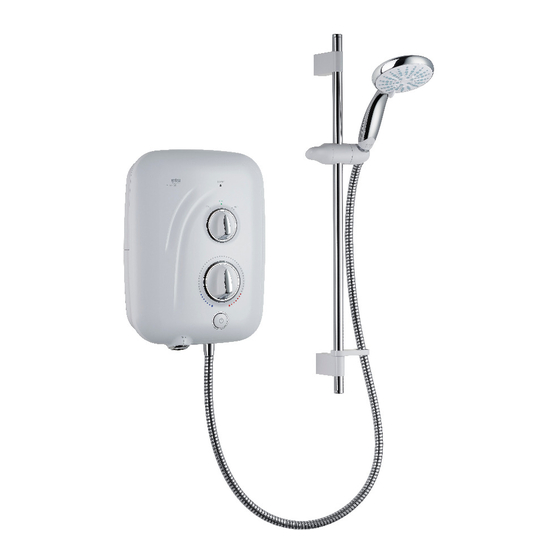
- Page 1 Mira Elite QT 9.8kW / 10.8kW These instructions must be left with the user Installation & User Guide 1265606-W2-A...
-
Page 2: Important Safety Information
DO NOT connect the outlet of the shower to any tap, control valve, trigger handset or showerhead other than those specified for use with this shower. Only Kohler Mira recommended accessories must be used. DO NOT perform any unspecified modifications, drill or cut holes in the shower or fittings other than instructed by this guide. - Page 3 DO NOT connect the outlet of the shower to any tap, control valve, trigger handset or showerhead other than those specified for use with this shower. Only Kohler Mira recommended accessories must be used. The showerhead must be descaled regularly. Any blockage of the showerhead or hose can cause damage to the shower.
-
Page 4: Recommended Usage
Introduction Thank you for choosing a Mira shower. To enjoy the full potential of your new shower, please take time to read this guide thoroughly, and keep it handy for future reference. Products manufactured by Kohler Mira Ltd are designed to be safe, provided that they are installed, used and maintained in good working order, in accordance with our instructions and recommendations. -
Page 5: Pack Contents
Pack Contents 1 x Shower Unit 1 x Component Pack (shower unit) 2 x Caps 2 x Slide Bar Supports 1 x Clamp Bracket 1 x Showerhead 1 x Hose Retaining Ring 2 x Washers 1 x Hose 1 x Slide Bar 1 x Installation &... -
Page 6: Specifications
2006/95/EC Low Voltage Directive, 2004/108/EC EMC Directive, 2011/65/EU RoHS Directive. The Mira Elite QT is a high power appliance and is subject to conditional connection. If the main electrical supply fuse is rated less than 80 Amps, the local electricity supply company must be contacted to confirm if the electrical supply is adequate. -
Page 7: Installation
Installation Plumbing The plumbing installation must comply with all national or local water regulations and all relevant building regulations, or any particular regulation or practice specified by the local water supply company. The shower is designed to operate with a gravity fed water supply providing a pressure from 0.8 kPa* (0.008 bar / 80 millimetres head) to 100 kPa (1 bar / 10 metres head, the vertical distance from the base of the cold water cistern to the top of the shower unit). - Page 8 showerhead and the spill over lever of any toilet, bidet or other appliance with a Fluid Category 5 backflow risk. Shower Note! There will be occasions Unit Zone of when the hose retaining ring Backflow will not provide a suitable Risk solution for Fluid Category 3 installations.
- Page 9 DO NOT use a valve with a loose washer plate (jumper) as this can lead to a build up of static pressure. 12. The shower is not designed to be plumbed directly from the rear. For rear-entry supply, add an elbow to the supply pipe and connect as a rising or falling supply. We recommend a falling supply to prevent air lock in the pipework.
- Page 10 The example below is based on the “Pipework Schematic Diagram” with 15 mm pipework, A = 1.5 m, B = 0.75 m. Size Quantity Head Loss (mm) 15 mm Pipe 1.5 + (B) 0.75 2.25 22 mm Pipe + (B) 15 mm Elbow Number of Elbows 22 mm Elbow...
-
Page 11: Electrical Schematic Diagram
Check all electrical connections are tight, to prevent overheating, before switching on the electrical supply. DO NOT apply excessive force to the terminal block. DO NOT supply any other electrical equipment including extractor fans or pumps via the shower unit. DO NOT switch on the electrical supply until the plumbing has been completed and checked for leaks. -
Page 12: Installation Of The Shower Unit
Installation of the Shower Unit Warning, isolate the electrical and water supplies before installing the shower! Decide on a suitable position for the shower unit and fittings. See “Installation - Plumbing” for further details. Remove the cover screws, cover and Hold the template against the wall and service tunnel. - Page 13 Drill the fixing holes. DO NOT drill through the shower unit into the wall. DO NOT drill into buried cables or pipes. Thinned Section Rear Case Feed the water pipe and electrical For a falling water supply pipe, carefully cable to the inlet of the shower unit. remove the thinned section of the rear For rear inlet, use an elbow fitting.
- Page 14 Thoroughly flush the water supply Fix the shower unit to the wall, 3 x No. 8 x pipe. Rotate the inlet connector to suit 1¼” screws and wall plugs are supplied. the direction of the water supply. See “Installation - Plumbing” for further details.
- Page 15 (Live) = Brown Wire (Protective Earth) = Green / Yellow Sleeved Wire (Neutral) = Blue Wire Turn the water supply back off. Feed Refit the service tunnel. Align the the electrical cable into the shower controls with the spindles and refit the unit.
- Page 16 Installation of the Shower Fittings New Installation 600 mm Retrofit Installation 635 mm Max. Mark and drill the fixing points for Fix the brackets to the wall, 2 x No. 8 x the wall screws. New installations 45 mm screws and wall plugs are at a distance of 600 mm.
- Page 17 Fit the slide bar supports over the Remove the assembly, without moving mounting brackets and adjust the slide the supports on the slide bar. bar vertically. The slide bar should extend equally at both ends. Tighten the two slide bar clamping Fix the slide bar at both ends with the screws no more than half a turn to M4 screws supplied.
- Page 18 Showerhead Assembly Clamp Bracket Assembly Feed the hose through the retaining ring and screw to both the showerhead and shower unit. Use the washers supplied to seal the connections. Place the showerhead assembly into the clamp bracket assembly and check the operation. Turn the water supply back on.
- Page 19 AIR IN SYSTEM ? Start shower running, water is cold and Turn shower off. at maximum flow. Remove filter from shower unit. Push rod up until water flows freely. Refit filter, turn until locked. Turn temperature control to mid- Turn power control to eco. Water temperature.
-
Page 20: Operation
Operation Please read “Important Safety Information” before using the shower for the first time. Switch electrical supply on and start Set power control to low / eco / high. shower. Adjust temperature control until desired showering temperature is reached. Allow a few seconds for any temperature Check water temperature... -
Page 21: Effect Of Seasonal Changes
Please note when altering the shower temperature... CAUTION! Altering the temperature control rapidly can cause the water temperature to become briefly hotter or colder than required. For best results, adjust the temperature control a small amount and allow the temperature to stabilise. Continue to adjust until a comfortable showering temperature is reached. -
Page 22: User Maintenance
User Maintenance WARNING! PLEASE OBSERVE THE FOLLOWING TO REDUCE THE RISK OF FIRE, ELECTRIC SHOCK, INJURY OR PRODUCT DAMAGE: ■ No user serviceable parts can be accessed by removing the cover. Mains connections are exposed when the cover is removed. Only qualified, competent personnel should remove the cover. -
Page 23: Fault Diagnosis
• If the shower shows signs of a distinct change in performance indicating a need for maintenance. Only use genuine Kohler Mira replacement parts. If you require a Mira trained service engineer or agent, please see “Customer Service” on the back cover of this guide. Symptom... - Page 24 Symptom Cause Recommended Action Low water flow. Pump overheated or Wait 30 minutes for pump to cool No water flow. faulty. and reset automatically. If fault persists, contact your installer to (continued...) replace. Water flow stops and Stored water is blocked Turn shower off immediately! motor tone increases.
-
Page 25: Spare Parts
Spare Parts 1845.159 1845.155 Motor Mount (x5) Pump (includes 1746.436 pump elbow & clips) Thermal Switch 872.01 Microswitch 1788.429 On / Off 1845.153 Switching Terminal Assembly Block 1845.191 1845.158 Heater Tank Service 9.8kW Tunnel 1788.428 Heater Tank 10.8kW 1788.434 (includes microswitches) Solenoid (x4) - Page 26 Notes 1265606-W2-A...
- Page 27 Notes 1265606-W2-A...
-
Page 28: Customer Service
• The guarantee applies solely to the original Spares and Accessories installation under normal use and to the original We hold the largest stocks of genuine Mira purchaser only. The product must be installed and spares and accessories. Contact us for a price...
Need help?
Do you have a question about the Elite QT and is the answer not in the manual?
Questions and answers