Advertisement
PACKAGE CONTENTS
* 1x PoE switch
CONNECTION
C42-050-30-A
LAN LED
PoE LED
C42-050-30-B
24V LED
12V LED
LAN LED
PoE LED
LED DEFINITIONS
Power
Amber ON
Green ON
LAN
Grren Blinking
Amber ON
PoE
Amber Off
12V (C42-050-30-B only)
Amber ON
24V (C42-050-30-B only)
Amber ON
Application
C42-050-30-A / C42-050-30-B
C42-044-91-380
90W bt PoE Switch
C42-050-30-A / C42-050-30-B
Installed on the system ceiling
1. Attach the ceiling mount bracket to plasterboard, etc.
● It is recommended to add the fastening screw to the hole size of the ceiling, turn it with a screwdriver to install it.
The ceiling thickness that can be connected with the clamping bracket is from 5 to 45 mm.
● The recommended screw torque is 7kgf-cm±3.
● Install on the ceiling with sufficient strength.
● If you have to install it on rock wool ceiling and other weak ceiling panels, please provide enough reinforcement.
● The recommended ceiling opening size is φ150mm.
● The recommended minimum space (height) for ceiling switch installation is 140mm (For Installation and CAT5/6 cable routing.)
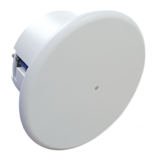
C42-050-30-A bt Ceiling PoE Switch
C42-050-30-B bt Ceiling PoE Switch
Quick Installation Guide
* 1x Quick Installation Guide
PWR LED
PD Port
Reset
PWR LED
PD Port
Reset
The Power LED lights up when the switch is connected to a power source.
Port is enabled and link established.
Port is transmitting and receiving data.
Indicates the PoE powered device (PD) is connected and the port supplies power successfully.
Indicates no powered device (PD) connected.
Have output 12VDC power.
Have output 24VDC power.
Wifi AP
Sensor
C42-050-30-B
bt PoE Input
GND
bt PoE Input
GND
Camera
Wifi AP
Network
Sensor
Speaker
P/N: 5019032602
at PoE Output
bt PoE Output
24VDC Output
12VDC Output
at PoE Output
bt PoE Output
Camera
Network
Speaker
C42-050-30-A
PoE (Data + Power)
Advertisement
Table of Contents

Related Manuals for AETEK C42-050-30-A


Summary of Contents for AETEK C42-050-30-A
- Page 1 C42-050-30-A bt Ceiling PoE Switch P/N: 5019032602 C42-050-30-B bt Ceiling PoE Switch Quick Installation Guide PACKAGE CONTENTS * 1x PoE switch * 1x Quick Installation Guide CONNECTION C42-050-30-A PWR LED PD Port LAN LED at PoE Output PoE LED bt PoE Output...
- Page 2 ●Remove the panel with a flat-head screwdriver. AETEK INC. 6F, No.192-1, Lien-Cheng Rd., Chung-Ho, New Taipei City, 235, Taiwan, R.O.C. Copyright © 2023 AETEK INC. All rights reserved. | T : +886- 2-82452822 | W : www.aetektec.com | E : sales@aetektec.com...
Need help?
Do you have a question about the C42-050-30-A and is the answer not in the manual?
Questions and answers