Table of Contents
Advertisement
Quick Links
Advertisement
Table of Contents
Troubleshooting

Related Manuals for SMC Networks HRR050-A 20 Series


Summary of Contents for SMC Networks HRR050-A 20 Series
- Page 1 HRX-OM-X071-B Operation Manual Installation ・ Operation Original Instructions Thermo-chiller HRR050-A -20- HRR050-W -20- HRR050-A -40- HRR050-W -40- Keep this manual available whenever necessary © 2021 SMC CORPORATION All Rights Reserved...
- Page 2 To the users Thank you for purchasing SMC’s Thermo chiller (hereinafter referred to as the “product”). For safety and long life of the product, be sure to read this operation manual (hereinafter referred to as the “manual”) and clearly understand the contents. ●...
-
Page 3: Table Of Contents
HRX-OM-X071 Contents Contents Chapter 1 Safety Instructions ............1-1 Before using the product ..................1-1 Reading the Manual ....................1-1 Hazards ........................1-2 1.3.1 Level of hazards ........................1-2 Definition of “Serious injury” and “Minor injury” ..............1-2 1.3.2 Product Label ......................1-3 Safety Measures ...................... - Page 4 HRX-OM-X071 Contents Chapter 4 Starting the Product ............4-1 Before Starting ......................4-1 Starting and Stopping ....................4-2 Operation ..........................4-2 4.2.1 4.2.2 Operation restart when alarm is generated ................. 4-3 4.2.3 Stopping the product ......................4-5 Adjustment of bypass valve ..................4-6 Check items after starting ..................
- Page 5 HRX-OM-X071 Contents 6.3.1 Option T1, T2【Inverter pump】 ..................... 6-2 Option Y【With feet / Without rack mounting brackets】 ........6-3 6.4.1 Option Y【With feet / Without rack mounting brackets】 ............6-3 6.4.2 Anti-quake bracket (Optional Accessories) ................6-4 Option Z ........................6-5 6.5.1 Option Z..........................
- Page 6 HRX-OM-X071 Contents 9.3.2 HRR050-W-20/40- ......................9-10 Cooling capacity ....................9-11 9.4.1 HRR050-A-20- ....................... 9-11 9.4.2 HRR050-W-20- ......................9-11 9.4.3 HRR050-A-40- ....................... 9-12 9.4.4 HRR050-W-40- ......................9-12 Heating capacity ....................9-13 9.5.1 HRR050-A/W-20- ......................9-13 9.5.2 HRR050-A/W-40- ......................9-13 Pump capacity......................9-14 9.6.1 HRR050-A/W-20-...
-
Page 7: Chapter 1 Safety Instructions
HRX-OM-X071 Chapter 1 Safety Instructions Chapter 1 Safety Instructions Before using the product, be sure to read and understand all the important actions highlighted in this manual. 1.1 Before using the product This chapter is intended to specifically describe the safety related issues for handling the product. -
Page 8: Hazards
HRX-OM-X071 Chapter 1 Safety Instructions 1.3 Hazards 1.3.1 Level of hazards The instructions given in this manual aim to assure the safe and correct operation of the product, and to prevent injury of operators or damage to the product. These instructions are grouped into three categories, Danger, Warning and Caution, which indicate the level of hazard, damage and also the degree of emergency. -
Page 9: Product Label
HRX-OM-X071 Chapter 1 Safety Instructions 1.4 Product Label Information about the product, such as Serial No. and Model No. can be found on the product label. This information is needed when contacting an SMC sales distributor. Model number Serial number Type and quantity of refrigerant... -
Page 10: Safety Measures
HRX-OM-X071 Chapter 1 Safety Instructions 1.5 Safety Measures 1.5.1 Safety instructions for use Follow the instructions below when using the product. Failure to follow the instructions may cause an accident and injury. Read and understand this manual carefully before using the product. ... -
Page 11: Emergency Measures
HRX-OM-X071 Chapter 1 Safety Instructions 1.6 Emergency Measures When emergency conditions such as natural disaster, fire and earthquake, or injury occurs, turn off the power supply switch. After that, be sure to shut off the breaker of the original power supply (customer's power supply equipment). -
Page 12: Waste Disposal
HRX-OM-X071 Chapter 1 Safety Instructions 1.7 Waste Disposal 1.7.1 Disposal of refrigerant and compressor oil The product uses hydro fluorocarbon type refrigerant (HFC) and compressor oil. Comply with the laws and regulations in each country for the disposal of refrigerant and compressor oil. The type and quantity of refrigerant is described on the “1.4 Product Label”. -
Page 13: Material Safety Data Sheet (Msds)
HRX-OM-X071 Chapter 1 Safety Instructions 1.8 Material Safety Data Sheet (MSDS) If the material safety data sheets of chemicals used in this product are needed, contact an SMC's sales distributor. Any chemicals used by the user must be accompanied by an MSDS. HRR Series 1.8 Material Safety Data Sheet (MSDS) - Page 14 HRX-OM-X071 Chapter 1 Safety Instructions 1.8 Material Safety Data Sheet (MSDS) HRR Series...
-
Page 15: Chapter 2 Name And Function Of Parts
HRX-OM-X071 Chapter 2 Name and Function of Parts Chapter 2 Name and Function of Parts 2.1 Model Number of Product The product can be ordered with the model number configured as shown below. The product needs to be handled in different ways depending on the part number. - Page 16 HRX-OM-X071 Chapter 2 Name and Function of Parts 2.1.2 HRR050-A/W-40- ①Cooling method,Cooling capacity ⑥Option3 Air-cooled refrigeration 4800W/5800W (50/60Hz) Null None 5500W/5900W (50/60Hz) Water-cooled refrigeration With feet / ②Pipe thread type Without rack mounting brackets Null no flow sensor, G (With Rc-G conversion fitting set) Z 1 no bypass valve,no particle filter, NPT (With Rc-NPTconversion fitting set...
-
Page 17: Hrr050-A-20/40- (Air Cooled Type)
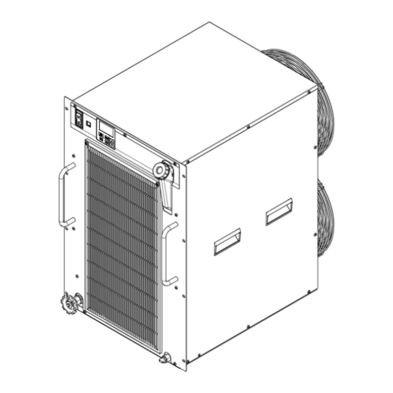
HRX-OM-X071 Chapter 2 Name and Function of Parts 2.2 Name and Function of Parts 2.2.1 HRR050-A-20/40- (Air cooled type) In the case of option Z, without bypass valve Fig 2-3 Names of the parts Table 2-1 Accessory list 2 copies ①... -
Page 18: Hrr050-W-20/40- (Water Cooled Type)
HRX-OM-X071 Chapter 2 Name and Function of Parts 2.2.2 HRR050-W-20/40- (Water cooled type) In the case of option Z, without bypass valve Fig 2-4 Names of the parts Table 2-2 Accessory list 2 copies ① Operation manual (English 1 copy/ Japanese 1 copy) Power supply connector ②... -
Page 19: Function Of Parts
HRX-OM-X071 Chapter 2 Name and Function of Parts 2.3 Function of Parts The function of parts is as follows Table 2-3 Function of parts Name Name Runs and stops the product and performs settings such as the circulating fluid temperature. Operation display panel For details, refer to ’’2.4 ’’. -
Page 20: Operation Display Panel
HRX-OM-X071 Chapter 2 Name and Function of Parts 2.4 Operation display panel The operation panel on the front of the product controls the basic operation of the product ℃ 図 2-5 操作表示パネル RUN/ ▲ MENU STOP ▼ RESET Table 2-4 Operation display panel Reference Function Name... -
Page 21: Chapter 3 Transport And Setting Up
HRX-OM-X071 Chapter 3 Transport and Setting Up Chapter 3 Transport and Setting Up Only persons who have sufficient knowledge and experience about the product and system are allowed to transport and set up the product. Especially pay attention to personal safety. 3.1 Transport The product is heavy and has potential danger at transport. -
Page 22: Installation
HRX-OM-X071 Chapter 3 Transport and Setting Up 3.2 Installation Do not set up the product in places possibly exposed to leakage of flammable gas. Should any flammable gas stay around the product, the product may cause a fire. Do not use the product outdoors. If the product subjected to rain or water splash it may cause electrical shock, fire or failure. - Page 23 HRX-OM-X071 Chapter 3 Transport and Setting Up Thermo-chiller installation in high altitude of 1000 meters or more Because of lower air density, the heat radiation efficiencies of the devices in the product will be lower in the location at altitude of 1000m or higher. For this reason, the maximum ambient temperature for the thermo-chiller operation and the cooling capacity will be reduced.
-
Page 24: Location
HRX-OM-X071 Chapter 3 Transport and Setting Up 3.2.2 Location Do not install in a location which can be subjected to any of the conditions in “3.2.1 Environment”. The air cooled product radiates heat from the air vent of the cooling fan. If the product is operated with insufficient air ventilation the internal temperature can exceed 40 C, which can cause and affect the... - Page 25 HRX-OM-X071 Chapter 3 Transport and Setting Up The water cooled product radiates heat to the facility water. It is necessary to supply the facility water. Please prepare the facility water system that satisfies the heat radiation and the facility water specifications below.
-
Page 26: Installation And Maintenance Space
HRX-OM-X071 Chapter 3 Transport and Setting Up 3.2.3 Installation and Maintenance Space It is recommended to keep the space around the product shown in Fig 3-1 Have an enough space for the ventilation for the product. Otherwise it may cause a lack of cooling capacity or/and stoppage of the product. Ensure there is enough space for maintenance. -
Page 27: Installation
HRX-OM-X071 Chapter 3 Transport and Setting Up 3.3 Installation 3.3.1 Mounting How to mount the product When mounting the prouduct to a cabinet, use a design which shall hold the weight at the bottom. Ensure safety with transportation test if the product is to be installed on a transportation device such as atrailer. -
Page 28: Electrical Wiring
HRX-OM-X071 Chapter 3 Transport and Setting Up 3.3.2 Electrical wiring Do not modify the internal electrical wiring of the product. Incorrect wiring may cause electric shock or fire. Also, modifying the internal wiring will void the product’s warranty. NEVER connect the ground to water line, gas pipe or lightning conductor. - Page 29 HRX-OM-X071 Chapter 3 Transport and Setting Up Power supply specifications, power supply cable and earth leakage breaker Prepare the power supply shown in the following table. For the connection between the product and power supply, use the power supply cable and earth leakage breaker shown below. An earth leakage breaker must be mounted to a position where the breaker is easily accessible and close to the thermo-chiller.
-
Page 30: Preparation And Wiring Of Power Supply Cable
HRX-OM-X071 Chapter 3 Transport and Setting Up 3.3.3 Preparation and wiring of power supply cable The electrical facilities should be installed and wired in accordance with local laws and regulations of each country and by a person who has knowledge and experience. ... - Page 31 HRX-OM-X071 Chapter 3 Transport and Setting Up Preparation Prepare the cable and individual socket or earth leakagebreaker shown in the table below. Cable Power supply Strip the sheath from both ends of the cable. Qty. x size voltage 3cores×12AWG 1-phase (3cores×3.5mm2)...
- Page 32 HRX-OM-X071 Chapter 3 Transport and Setting Up Assemble the power connector shell, gasket, ring and cable nut. Ring Cable nut Gasket Female Shell Recommended tightening torque: 1 to 2 N・m connector 200V type Cable nut2 Shell1 Female 1 Recommended tightening torque: 1 to 2 N・m connector 2 Recommended tightening torque: 5 N・m 400V type...
- Page 33 HRX-OM-X071 Chapter 3 Transport and Setting Up Connect the crimped terminals to the secondary side of the earth leakage breaker and grounding on the power supply facility Power supply connector connection Fig 3-7 HRR Series 3.3 Installation 3-13...
-
Page 34: Contact Input/Output Communication Wiring
HRX-OM-X071 Chapter 3 Transport and Setting Up 3.3.4 Contact input/output communication wiring Be sure to lock out and tag out the breaker of the facility power supply (the user’s machine power supply) before wiring. Use a connector that is specified. The capacity of the output contact of the product is limited. - Page 35 HRX-OM-X071 Chapter 3 Transport and Setting Up Table 3-6 Contact input/output pin number Initial value Application Division (Default setting) DC 24V output Output DC 24V output Output DC 24V output Output Contact input signal 1 Input None COM of contact output signal 1 Output COM of contact output signal 2 Output...
-
Page 36: Wiring Of Run/Stop Signal Input And Remote Signal Input
HRX-OM-X071 Chapter 3 Transport and Setting Up 3.3.5 Wiring of run/stop signal input and remote signal input Run/Stop signal input and remote signal input enable the product to run/stop remotely by applying a contact signal input. This chapter illustrates examples of wiring. -
Page 37: Wiring Of Contact Output Signal
HRX-OM-X071 Chapter 3 Transport and Setting Up 3.3.6 Wiring of contact output signal Contact output signals are the signals that output the status of this product. Be sure to turn OFF the breaker of the facility power supply (the user's machine power supply) before wiring. -
Page 38: Communication Wiring
HRX-OM-X071 Chapter 3 Transport and Setting Up 3.3.7 RS-485 communication wiring Serial communication RS-485, operation Start/Stop, setting and reading of circulating fluid temperature, and reading of alarm condition can be performed by remote control. Refer to Operation Manual “Communication Function” for more details. ... - Page 39 HRX-OM-X071 Chapter 3 Transport and Setting Up Wiring of interface communication cable Be sure to turn OFF the breaker of the facility power supply (the user's machine power supply) before wiring. Connecting to PC RS-485 cannot be directly connected to a normal PC. Use an RS-232C/RS485 converter which is available on the market.
-
Page 40: Rs-232C Communication Wiring
HRX-OM-X071 Chapter 3 Transport and Setting Up 3.3.8 RS-232C communication wiring Serial communication RS-232C, operation start/stop, setting and reading of circulating fluid temperature, and reading of alarm condition can be performed by remote control. Refer to Operation Manual “Communication Function” for more details. ... -
Page 41: Piping
HRX-OM-X071 Chapter 3 Transport and Setting Up 3.4 Piping Connect piping firmly. Incorrect piping might cause leakage of supplied or drained fluid and wet surrounding area and facility. Use caution not to allow dust and foreign matter to enter the water circuit, etc. - Page 42 HRX-OM-X071 Chapter 3 Transport and Setting Up How to connect piping Ensure that the power source and the power supply of the Product is turned off (or the power plug is disconnected). This product generates an alarm and stops running when the circulating fluid flow rate becomes 5 L/min or less.
- Page 43 HRX-OM-X071 Chapter 3 Transport and Setting Up In case of water-cooled type, please also connect the piping of the facility water inlet and outlet of the customer’s water source equipment. Facility water outlet Rc3/8 To the user’s water source inlet From the outlet Facility water inlet From the user’s...
-
Page 44: Fill Of Circulating Fluid
HRX-OM-X071 Chapter 3 Transport and Setting Up 3.5 Fill of circulating fluid Ensure that the power source and the power supply of the product is turned off. Check the drain port is plugged to prevent the supplied circulating fluid from draining out. Open the circulating fluid inlet cap by turning it counterclockwise, and fill the circulating fluid within the range from LOW to HIGH shown on the level gauge. -
Page 45: Chapter 4 Starting The Product
HRX-OM-X071 Chapter 4 Starting the Product Chapter 4 Starting the Product Only people who have sufficient knowledge and experience about the product and its accessories are allowed to start and stop the product. 4.1 Before Starting Check the following points before starting the product. ... -
Page 46: Starting And Stopping
HRX-OM-X071 Chapter 4 Starting the Product 4.2 Starting and Stopping 4.2.1 Operation Please supply power to this product Turn on the power switch. The operation display panel lights up. At this point, this product is in the "Stopped" state (Please note that operation is started after the power is turned on when the operation signal is sent in the remote setting state.) 200V type 400V type... -
Page 47: Operation Restart When Alarm Is Generated
HRX-OM-X071 Chapter 4 Starting the Product [Tips] In the first operation after water supply, be sure to start the operation with the bypass valve open. The pump may not be susupply the fluid, which reduces the life of the pump. After confirming that the circulating fluid has flowed, adjust the pressure on flow rate with the bypass valve. - Page 48 HRX-OM-X071 Chapter 4 Starting the Product To stop the product when only the pump is running, press and hold the [RUN/STOP] key for approximately 5 seconds. (When this operation is performed, an alarm "AL27: forced a stop " occurs.) ℃ °...
-
Page 49: Stopping The Product
HRX-OM-X071 Chapter 4 Starting the Product 4.2.3 Stopping the product Press and hold the [RUN / STOP] key for 1 second. [RUN] lamp goes out and operation stops. *It takes about 10 seconds of operation to prepare to stop before it stops. During the stopping preparation the [RUN] lamp flashes. -
Page 50: Adjustment Of Bypass Valve
HRX-OM-X071 Chapter 4 Starting the Product 4.3 Adjustment of bypass valve This product has a circulating fluid bypass valve installed(Not installed for option Z). The bypass valve is opened when delivered. Adjust valve opening according to customer's usage situation. Also, if circulating fluid temperature is not stabilized, shortage of circulating fluid flow may be considered. -
Page 51: Chapter 5 Display And Setting Of Various Functions
HRX-OM-X071 Chapter 5 Display and Setting of Various Functions Chapter 5 Display and Setting of Various Functions Read and understand this manual carefully before changing the settings. 5.1 List of Functions The product can have the displays and settings shown in Table 5-1. Table 5-1 List of functions Reference... -
Page 52: Function
HRX-OM-X071 Chapter 5 Display and Setting of Various Functions 5.2 Function 5.2.1 Key operations The key operation of this product is shown in Fig 5 -1 Key operation list (1/4) to Fig 5-4 Key operation list (4/4). Basic setting mode Main menu Alarm display menu Maintenance notif... - Page 53 HRX-OM-X071 Chapter 5 Display and Setting of Various Functions y menu Maintenance notification menu Advanced mANT setting MENU MENU Press and hold MENU MENU mode for approximately 5 second. ▲/▼ Maintenance mT01 Alarm number MENU notification number (Alarm number minimum) (Notification number minimum)...
- Page 54 HRX-OM-X071 Chapter 5 Display and Setting of Various Functions Basic Advance setting mode setting Alarm setting menu Monitor menu Standard setting menu mode ALST MENU MENU MENU MENU MENU MENU ▲/▼ ▲/▼ Changing of circulating fluid Setting of ambient temperature ▲/▼...
- Page 55 HRX-OM-X071 Chapter 5 Display and Setting of Various Functions Communication setting menu Reset menu Information moniter menu Alarm history menu COmm INFO ALmh MENU MENU MENU MENU MENU MENU MENU Example ▲/▼ ▲/▼ ▲/▼ ▲/▼ ▲/▼ Contact output signal 2 Serialprotocol Model Setting date reset...
-
Page 56: List Of Parameters
HRX-OM-X071 Chapter 5 Display and Setting of Various Functions 5.3 List of parameters The parameter list of this product is shown below. 5.3.1 Main Menu Table 5.3-1 Main menu parameter list Display unit Initial value Reference ScreenNo. Unit display (Default setting) page Upper stage(White)... -
Page 57: Monitor Menu
HRX-OM-X071 Chapter 5 Display and Setting of Various Functions 5.3.4 Monitor Menu Table 5.3-4 Monitor menu parameter list Display unit Reference ScreenNo. Unit display page Upper stage(White) Lower stage(Green) MENU - screen No.1 Temperature of the compressor inlet REF⇒TEMP ℃ screen No.2 5.5.2... -
Page 58: Standard Setting Menu
HRX-OM-X071 Chapter 5 Display and Setting of Various Functions 5.3.5 Standard setting menu Table 5.3-5 Standard setting menu parameter list Display unit Unit Reference Upper stage(White) ScreenNo. Item Lower stage display page (Green) Initial value Select/setting range - - - MENU screen No.1... -
Page 59: Alarm Setting Menu
HRX-OM-X071 Chapter 5 Display and Setting of Various Functions 5.3.6 Alarm Setting Menu Table Alarm setting menu Parameter list 5.3-6 Display unit Screen Unit Reference Item Upper stage(White) Lower stage display page (Green) Initial value S elect/setting range - AL.ST -... -
Page 60: Communication Setting Menu
HRX-OM-X071 Chapter 5 Display and Setting of Various Functions Not displayed for option Z. 5.3.7 Communication setting menu Table Communication setting menu Parameter list 5.3-7 Display unit Screen Reference Item Upper stage(White) Lower stage page (Green) Initial value Select/setting range -... -
Page 61: Reset Menu
HRX-OM-X071 Chapter 5 Display and Setting of Various Functions SW2 / A.SEL / M.SEL 5.3.8 Reset menu Table Reset menu parameter list 5.3-8 Display unit Reference ScreenNo. Item Upper stage(White) Lower stage page (Green) Initial value Select/setting range - - MENU screen No.1... -
Page 62: Basic Setting Mode
HRX-OM-X071 Chapter 5 Display and Setting of Various Functions 5.4 Basic setting mode 5.4.1 Screen configuration The screen of this product shows "basic setting mode" and " advanced setting mode". In "basic setting mode", only temperature can be set. Other settings are done in " advanced setting mode". "Basic setting mode"... - Page 63 HRX-OM-X071 Chapter 5 Display and Setting of Various Functions Circulating fluid flow display Press the [▼] key. The circulating fluid flow rate is displayed on the digital display. ( Not displayed for options Z and Z1. ) Circulating fluid flow The display flow rate does not include the circulating fluid flow rate flowing in the bypass of this product.
-
Page 64: Alarm Display Menu
HRX-OM-X071 Chapter 5 Display and Setting of Various Functions 5.4.3 Alarm display menu The alarm display menu appears when an alarm is generated. If an alarm has not occurred, this menu will not be displayed. For alarm contents, refer to Chapter 7 "Alarm notification and troubleshooting"... -
Page 65: Notice For Maintenance Menu
HRX-OM-X071 Chapter 5 Display and Setting of Various Functions 5.4.4 Notice for maintenance Menu A notice for maintenance will occur when it is time to replace components such as pumps and fans. In addition, if the usable time of the dust filter and the DI filter is set beforehand, a notice for maintenance will be generated when the usage time is reached. - Page 66 HRX-OM-X071 Chapter 5 Display and Setting of Various Functions Notice for maintenance menu TOP screen This is the TOP screen of the notice for maintenance menu. Press the [▼] key. Displays the notice for maintenance number currently occurring in order of maintenance notification number.
-
Page 67: Advanced Setting Mode
HRX-OM-X071 Chapter 5 Display and Setting of Various Functions 5.5 Advanced setting mode 5.5.1 Switch to advanced setting mode Settings other than circulating fluid temperature setting are performed in " Advanced setting mode". While displaying the main menu TOP screen of "Basic setting mode" Press and hold the [MENU] key for 5 seconds to switch to "Advanced setting mode". - Page 68 HRX-OM-X071 Chapter 5 Display and Setting of Various Functions Temperature at the compressor inlet. Press the [▼] key. Displays temperature at the compressor inlet. ℃ Temperature at the compressor inlet. REF ⇒ TEMP ( Alternately displayed ) Ambient temperature Press the [▼] key. Displays the ambient temperature (ventilated air temperature of this product).
-
Page 69: Display Contents Of The Standard Setting Menu
HRX-OM-X071 Chapter 5 Display and Setting of Various Functions 5.5.3 Display contents of the standard setting menu Perform settings other than temperature setting. Standard menu TOP screen When the [MENU] key is pressed while the monitor menu TOP screen is displayed the screen switches to the "Standard setting menu TOP screen". - Page 70 HRX-OM-X071 Chapter 5 Display and Setting of Various Functions When EASY mode set to OFF, a short press of the [MENU] key selects " Advanced setting mode" . To disable EASY mode, press the [ENT] key. "ON" flashes. Pressing the [▼] key while flashing will switch to the "OFF" . When the [ENT] key is pressed, the flashing ends and the EASY mode is disabled.
- Page 71 HRX-OM-X071 Chapter 5 Display and Setting of Various Functions Offset mode Press the [▼] key. Displays setting screen. offset mode OFF: Offset mode disabled / mD1: Offset mode 1 / mD2: Offset mode 2 / mD3: Offset mode 3 MD OFSET ⇒...
- Page 72 HRX-OM-X071 Chapter 5 Display and Setting of Various Functions MODE Explanation Control the temperature so that the discharge temperature of the circulating fluid is circulating fluid set temperature + offset MODE1 temperature. Circulating fluid temperature indicates the circulating fluid discharge temperature. Control the temperature so that the discharge temperature of the circulating fluid is circulating fluid set temperature.
- Page 73 HRX-OM-X071 Chapter 5 Display and Setting of Various Functions This produuct Your system Circulating fluid temperature 29℃ Serial communication Discharge temperature 30℃ Circulating fluid display temperature 29℃ Heat radiation Circulating fluid set 1℃ temperature 30℃ Offset temperature 29℃ -1℃ ■ Example of MODE 3 When the offset temperature is 1 C, the thermo-chiller controls the temperature at 31...
- Page 74 HRX-OM-X071 Chapter 5 Display and Setting of Various Functions This function controls the offset temperature to the circulating fluid discharge temperature Control range of the circulating fluid temperature is 5.0 C to 35.0 When the circulating fluid temperature is set to 5.0 C and the offset temperature to -20.0 C, the offset temperature is automatically...
- Page 75 HRX-OM-X071 Chapter 5 Display and Setting of Various Functions Electric conductivity setting value The set value of electric conductivity can be set within the range of "0.5 to 45.0 μS / cm".The initial value is "25.0 μS / cm". When the [ENT] key is pressed, the set value flashes.
- Page 76 HRX-OM-X071 Chapter 5 Display and Setting of Various Functions Press the [▼] key. Display as shown below. It is not used with this product ℃ Unused EXT ⇒ HITMP ⇒ LIMIT( Alternately displayed ) Press the [▼] key. Display as shown below. It is not used with this product ℃...
- Page 77 HRX-OM-X071 Chapter 5 Display and Setting of Various Functions [11] "Add output of temperature range upper limit alarm": Set to "OFF". "Temperature range lower limit alarm switching": Set to "OFF". [12] "Add output of temperature range lower limit alarm": Set to "OFF". [13] Operation Chiller...
- Page 78 HRX-OM-X071 Chapter 5 Display and Setting of Various Functions TEMP READY stability time Press the [▼] key. Displays TEMP READY stability time setting screen. TEMP READY stability time ( Setting range :10 to 9999 sec) READY ⇒ TIME( Alternately displayed ) TEMP READY alarm of monitoring start time Press the [▼] key.
- Page 79 HRX-OM-X071 Chapter 5 Display and Setting of Various Functions 【Temperature range monitoring function setting example 1】 Circulating fluid temperature at start of operation: about °C °C [2] Circulating fluid set temperature:15 Temperature range monitoring function (upper limit) 」 : set to 「20.0 °C 」...
- Page 80 HRX-OM-X071 Chapter 5 Display and Setting of Various Functions State ⑨: Manual reset of alarm, "AL.14", "AL.15" cancellation as monitoring condition is not included. 【Temperature range monitoring function setting example 2】 [1] Circulating fluid temperature at start of operation: about 25℃ [2] Circulating fluid set temperature:15℃...
- Page 81 HRX-OM-X071 Chapter 5 Display and Setting of Various Functions State ⑤: Temperature monitoring enters the upper and lower limit range, "TEMP OUT" output OFF. State ⑥: Since the temperature range is again within the monitoring range, "AL.14" will not be reported and "TEMP OUT" Output OFF continues. State ⑦: AL.14 report since 45 sec has elapsed since the circulating fluid temperature deviated, because it is outside the upper temperature monitoring range.
- Page 82 HRX-OM-X071 Chapter 5 Display and Setting of Various Functions Press the [▼] key. Displays temperature range monitor start time setting screen After operation starts, monitoring of the temperature range starts after a set time (sec). Temperature range Monitor start time (setting range :0 to 9999 sec) TEMP ⇒...
-
Page 83: Alarm Setting Menu
HRX-OM-X071 Chapter 5 Display and Setting of Various Functions DI filter replacement time Press the [▼] key. Displays DI filter replacement time setting screen. DI filter replacement time DI ⇒ TIME( Alternately displayed ) DI filter replacement time The DI filter maintenance time can be set by the user as a reminder to replace the filter. - Page 84 HRX-OM-X071 Chapter 5 Display and Setting of Various Functions Changing of circulating fluid discharge pressure rise alarm behaviour Press the [▼] key. Displays screen for changing the chiller behaviour when the circulating fluid discharge pressure rise alarm occurs. Operation at occurrence of circulating fluid discharge pressure rise alarm HIPRS ⇒...
- Page 85 HRX-OM-X071 Chapter 5 Display and Setting of Various Functions Changing of low flow rate alarm behaviour Press the [▼] key. Displays screen for changing the chiller behaviour when the low flow rate alarm occurs.(In the case of option Z, Z1, this item will not be displayed.) Operation at occurrence of low flow rate alarm LOFL ⇒...
- Page 86 HRX-OM-X071 Chapter 5 Display and Setting of Various Functions Changing of electric conductivity rise alarm Press the [▼] key. Displays screen for setting value of electric conductivity rise alarm threshold. Displayed only when Option DM is selected [With electric conductivity control function, Applicable to DI water piping].
- Page 87 HRX-OM-X071 Chapter 5 Display and Setting of Various Functions Output of NOT TEMP READY Press the [▼] key. Displays screen for setting the output of the NOT TEMP READY signal. Output of NOT TEMP READY signal TEMP ⇒READY ⇒ OUTP( Alternately displayed ) The user can select whether thre is an output signal when alarm "AL13 NOT TEMP READY"...
- Page 88 HRX-OM-X071 Chapter 5 Display and Setting of Various Functions Output of circulating fluid temperature rise signal Press the [▼] key. Displays screen for setting the output of circulating fluid temperature rise signal. Output of circulating fluid temperature rise signal TEMP ⇒OUTHI ⇒ OUTP( Alternately displayed) The user can select whether there is an output signal when alarm "AL14 circulating fluid temperature rise"...
- Page 89 HRX-OM-X071 Chapter 5 Display and Setting of Various Functions Output of the circulating fluid temperature drop alarm. Press the [▼] key. Displays screen for output setting of the circulating fluid temperature drop alarm. Output of the circulating fluid temperature drop alarm. TEMP ⇒OUTLO ⇒...
- Page 90 HRX-OM-X071 Chapter 5 Display and Setting of Various Functions Ambient temperature lower limit alarm Press the [▼] key. Displays screen for setting the lower limit of the ambient temperature alarm. Displayed for air-cooled type only. (This item is not displayed for water-cooled type) ℃...
- Page 91 HRX-OM-X071 Chapter 5 Display and Setting of Various Functions Contact input signal 1 delay timer for reading Press the [▼] key. Displays screen for setting the Contact input signal 1 Delay timer for reading. Setting of the contact input signal 1 delay timer for reading INP1 ⇒...
- Page 92 HRX-OM-X071 Chapter 5 Display and Setting of Various Functions Contact input signal 2 delay timer Press the [▼] key. Displays screen for setting the Contact input signal 2 detection delay timer for reading. Setting of the contact input signal 2 delay timer for reading INP2⇒...
- Page 93 HRX-OM-X071 Chapter 5 Display and Setting of Various Functions Communication error alarm detection time Press the [▼] key. Displays screen for setting the communication error alarm detection time. Communication error alarm detection time COMM ⇒ TIME( Alternately displayed ) Time (sec.) to generate alarm AL29: Communication error can be changed. ●...
- Page 94 HRX-OM-X071 Chapter 5 Display and Setting of Various Functions Table 5.5-1 List of alarms for which isolated pump operation is available Display Alarm Initial Alarms which allow to Alarm name Upper line Lower line value continue pump operation (White) (Green) AL01 Low level in tank AL01...
- Page 95 HRX-OM-X071 Chapter 5 Display and Setting of Various Functions Temperature for pump to continue operation when alarm is generated. Press the [▼] key. Displays screen for setting the upper limit of temperature for the pump to continue operation when an alarm is generated. ℃...
-
Page 96: Communication Setting Menu
HRX-OM-X071 Chapter 5 Display and Setting of Various Functions 5.5.5 Communication setting menu Contact input and serial communication can be performed. Refer to the Operation Manual Communication Function for more details. Communication setting menu TOP screen When “MENU” key is pressed while Alarm Setting Menu TOP screen is displayed, the display is changed to the top of “Communication setting menu”. - Page 97 HRX-OM-X071 Chapter 5 Display and Setting of Various Functions RS-485 terminal unit Press the [▼] key. Displays screen for setting RS-485 terminal unit. RS-485 terminal unit Select RS-485 terminal unit. Initial value Set value Contents ○ No terminal ― With terminal Slave addresses Press the [▼] key.
- Page 98 HRX-OM-X071 Chapter 5 Display and Setting of Various Functions Displays the function for the Contact input signal 1. Initial value Set value Contents ○ No input signal RNST ― Run / stop signal is input ― Run signal is input ―...
- Page 99 HRX-OM-X071 Chapter 5 Display and Setting of Various Functions Displays the function of the Contact input signal 2. Initial value Set value Contents ○ No input signal STOP ― Stop signal input ― External switch signal input Contact input signal 2 type Press the [▼] key.
- Page 100 HRX-OM-X071 Chapter 5 Display and Setting of Various Functions Initial value Set value Explanation (Default setting) ― No output signal ○ Operation status signal output Remote status signal output ― EXTC ― Unused ― Ready completion (TEMP READY) signal output TOUT ―...
- Page 101 HRX-OM-X071 Chapter 5 Display and Setting of Various Functions Contact output signal 1 Select maintenance Press the [▼] key. Displays screen for setting the selected maintenance for the Contact output signal 1. The alarm is valid when the “selected maintenance status signal output”...
- Page 102 HRX-OM-X071 Chapter 5 Display and Setting of Various Functions Contact output signal 2 Operation Press the [▼] key. Displays screen for setting the operation of the Contact output signal 2. Contact output signal 2 operation DOUT ⇒ SEL( Alternately displayed ) Select the Contact output signal 2 operation.
- Page 103 HRX-OM-X071 Chapter 5 Display and Setting of Various Functions Displays the function of the Contact output signal 3. Initial value Set value Explanation (Default setting) ― No output signal ― Operation status signal output ― Remote status signal output EXTC ―...
-
Page 104: Reset Menu
HRX-OM-X071 Chapter 5 Display and Setting of Various Functions Contact output signal 3 Select maintenance Press the [▼] key. Displays screen for setting the selected maintenance of Contact output signal 3. The alarm is valid when the “selected maintenance status signal output” is active. - Page 105 HRX-OM-X071 Chapter 5 Display and Setting of Various Functions This function resets all the set values. Use caution when operating this function.It is recommended to record the set data before resetting. Reset of operation time of the pump Press the [▼] key. Displays screen for resetting the operation time of the pump. Reset of pump operation time PUMPT ⇒...
- Page 106 HRX-OM-X071 Chapter 5 Display and Setting of Various Functions Reset of operation time of the fan Press the [▼] key. Displays screen for resetting the operation time of the fan. Displayed for air-cooled type only. Reset of fan operation time FANT ⇒...
- Page 107 HRX-OM-X071 Chapter 5 Display and Setting of Various Functions Reset the operation time of the DI filter Press the [▼] key. Displays screen for resetting the operation time of the DI filter. Displayed for the option DM (With electric conductivity control function, Applicable to DI water piping) only.
-
Page 108: Information Monitor Menu
HRX-OM-X071 Chapter 5 Display and Setting of Various Functions 5.5.7 Information Monitor Menu Displays the product No, programme version, and operation times. Information Monitor Menu TOP screen When “MENU” key is pressed while Reset Menu TOP screen is displayed, the display is changed to the “Information Monitor Menu TOP screen”. - Page 109 HRX-OM-X071 Chapter 5 Display and Setting of Various Functions Program version Press the [▼] key. Displays program version of the product. Program version Operating time Press the [▼] key. Displays accumulated operating time of the thermo-chiller. Accumulated operating time of the thermo-chiller Operation time is accumulated up to 1,000,000 hour.
- Page 110 HRX-OM-X071 Chapter 5 Display and Setting of Various Functions Operation time of the fan Press the [▼] key. Displays accumulated operation time of the fan. Displayed for air-cooled type only. Accumulated operation time of the fan Operation time is accumulated up to 1,000,000 hour. Values are displayed alternately when exceeding 9999 hours.
- Page 111 HRX-OM-X071 Chapter 5 Display and Setting of Various Functions Press the [▼] key. Displays serial communication status. Status code COMM ⇒ STUS (Alternately displayed) Refer to the table below for the status code. Communication Contents status code 8001 Normal message 4801 Number of data is different 4401...
-
Page 112: Alarm History Menu
HRX-OM-X071 Chapter 5 Display and Setting of Various Functions 5.5.8 Alarm History menu Displays the number of alarms and the accumulated time of energization when each alarm occurred. A maximum of 150 alarms are displayed. When “MENU” key is pressed while Information Monitor Menu TOP screen is displayed, the display is changed to the “Alarm History menu TOP screen”. -
Page 113: Chapter 6 Option
HRX-OM-X071 Chapter 6 Option Chapter 6 Option 6.1 Option DM【With electric conductivity control function, Applicable to DI water piping】 6.1.1 Option DM【With electric conductivity control function, Applicable to DI water piping】 This function is available for customers who selected option DM (With electric conductivity control function, Applicable to DI water piping). -
Page 114: Option M【Applicable To Di Water Piping
HRX-OM-X071 Chapter 6 Option 6.2 Option M【Applicable to DI water piping】 6.2.1 Option M【DI water (Applicable to DI water piping】 This option is for customers who use DI water (pure water) as circulating fluid. Stainless (include heat exchanger brazing), Circulating fluid wetted materials Aluminum oxide ceramic, SiC, Carbon, PP, PE, POM, FKM, EPDM, PVC (No. -
Page 115: Option Y【With Feet / Without Rack Mounting Brackets
HRX-OM-X071 Chapter 6 Option 6.4 Option Y【With feet / Without rack mounting brackets】 6.4.1 Option Y【With feet / Without rack mounting brackets】 Rack mounting brackets are removed as they are not necessary when the product is not mounted in a rack. This option has rubber feet for installing the product on the floor. -
Page 116: Anti-Quake Bracket (Optional Accessories)
HRX-OM-X071 Chapter 6 Option 6.4.2 Anti-quake bracket (Optional Accessories) Bracket for earthquakes. Only when option Y is selected, this brackets can be mounting. This brackets can not be mounting to products other than option Y. Anchor bolt (M8) suitable for the flooring material should be prepared separately by user. -
Page 117: Option Z
HRX-OM-X071 Chapter 6 Option 6.5 Option Z 6.5.1 Option Z It is a specification with the following parts removed. Bypass valve Flow sensor Particle filter Water leakage sensor When this option is selected, the following functions cannot be used. Flow rate display ... - Page 118 HRX-OM-X071 Chapter 6 Option 6.5 Option Z HRR Series...
-
Page 119: Chapter 7 Alarm Notification And Troubleshooting
HRX-OM-X071 Chapter 7 Alarm Notification and Troubleshooting Chapter 7 Alarm Notification and Troubleshooting 7.1 Alarm Notification When any alarm occurs,the product responds with the following conditions. The [ALARM] (“ALM”, “WRN”) light blinks. The alarm buzzer sounds. The alarm number is displayed in the upper level window on the digital display. - Page 120 HRX-OM-X071 Chapter 7 Alarm Notification and Troubleshooting When multiple alarms are generated, the alarm codes are displayed one by one by pressing the [▲ / ▼] key. Press the [MENU] key to display the TOP screen of the alarm menu.
-
Page 121: Alarm Buzzer Stop
HRX-OM-X071 Chapter 7 Alarm Notification and Troubleshooting 7.2 Alarm Buzzer Stop The alarm buzzer sounds to notify when the alarm signal is output. How to stop the alarm buzzer. Press the [RESET] key. The alarm buzzer is stopped. 【Tips】... -
Page 122: Troubleshooting
HRX-OM-X071 Chapter 7 Alarm Notification and Troubleshooting 7.3 Troubleshooting 7.3.1 Alarm contents, causes, and troubleshooting The troubleshooting method depends which alarm has been generated. Refer to ’’Table 7-1 Alarm code list and Troubleshooting” This page explains how to reset the alarm signal condition after eliminating the cause of the alarm. - Page 123 HRX-OM-X071 Chapter 7 Alarm Notification and Troubleshooting Table 7-1 Alarm code list and Troubleshooting Display unit Alarm Cause / Remedy Description Initial value Upper stage Lower stage (Press the reset key after eliminating the cause.) (White) (Green) AL01 Low level in tank AL01 LOW⇒LEVEL⇒FLT Fluid level shown by the fluid level meter has fallen.
-
Page 124: Other Errors
HRX-OM-X071 Chapter 7 Alarm Notification and Troubleshooting 7.4 Other Errors How to check other errors The causes and remedies for failures that are not indicated by alarm numbers are shown in “Table 7-2” Table 7-2 Causes and remedies for failures without alarm number Content of Cause Remedy... -
Page 125: Chapter 8 Control, Inspection, Exchange And Cleaning
HRX-OM-X071 Chapter 8 Control, Inspection, Exchange and Cleaning Chapter 8 Control, Inspection, Exchange and Cleaning 8.1 Quality Control of Circulating Fluid and Facility Water Use specified fluids only. If other fluids are used, they may damage the product, causing fluid leakage, or result in hazards such as electric shock or leakage of electricity. -
Page 126: Inspection, Exchange, Cleaning
HRX-OM-X071 Chapter 8 Control, Inspection, Exchange and Cleaning 8.2 Inspection, exchange, cleaning Do not perform key operation or setting of this equipment with wet hands. Do not touch the electrical parts such as the power supply plug. It may cause an electric shock. ... -
Page 127: Daily Check
HRX-OM-X071 Chapter 8 Control, Inspection, Exchange and Cleaning 8.2.1 Daily check Check the items listed below. If any abnormality is found, stop the operation of the product and turn the power supply OFF, and ask for service. Table 8-1 Daily check items Item Contents of check ・... -
Page 128: Monthly Check
HRX-OM-X071 Chapter 8 Control, Inspection, Exchange and Cleaning 8.2.2 Monthly check Table 8-2 Contents of monthly check Item Contents of check Ventilating condition Clean the ventilating Make sure the ventilating grilles are not clogged (air cooled type) grilles. with dust, etc. Facility water Make sure the facility water is clean and contains Check the facility water. -
Page 129: Inspection Every 3 Months
HRX-OM-X071 Chapter 8 Control, Inspection, Exchange and Cleaning Cleaning filter Clean the filter with a long bristled brush or by air blow. Fig. 8-3 Cleaning of the dust-proof filter Mounting of the dust-proof filter Reassemble the filters in the reverse order to the removing procedure. (Recommended tighten torque of filter panel holding screws: 1.5 N ·... - Page 130 HRX-OM-X071 Chapter 8 Control, Inspection, Exchange and Cleaning Replacement of circulating fluid Replace the circulating fluid with new clean fluid periodically, or it may get algae or decompose. Circulating fluid to be supplied in the tank should satisfy the water quality specified in “...
- Page 131 HRX-OM-X071 Chapter 8 Control, Inspection, Exchange and Cleaning Discharge the facility water. Please refer to "8.3.2 Discharge of the facility Water". The strainer is installed on the back of the product. Remove the strainer using a tool such as a spanner. When removing the strainer, product should be fixed to do not move.
-
Page 132: Inspection Every 6 Months
HRX-OM-X071 Chapter 8 Control, Inspection, Exchange and Cleaning 8.2.4 Inspection every 6 months Check for water leakage from pump(200V type only) Remove the filter panel and check the pump for excessive leakage. If the leakage is found, replace the mechanical seal. ... -
Page 133: Stop For A Long Time
HRX-OM-X071 Chapter 8 Control, Inspection, Exchange and Cleaning 8.3 Stop for a Long Time If there is a concern that the product will not be operated for a long period of time or there is a risk of freezing, conduct the following operations. Turn off the user’s power supply (breaker). - Page 134 HRX-OM-X071 Chapter 8 Control, Inspection, Exchange and Cleaning Blow out circulating fluid inside of piping of this product by air blow.Blow air (pressere: 0.05 MPa or less, about one minite) from circulating fluid returen port.The fluid will come out from drain port and circulating fluid outlet.When executing this operation, tank cap should be closed and bypass valve should be opened.
- Page 135 HRX-OM-X071 Chapter 8 Control, Inspection, Exchange and Cleaning Remove the filter case by using maintenance handle which is supplied with product. Please note that circulating fluid may flow out from the case when removing filter case. Discharge circulating fluid inside of filter case.Do not drop out filter element from inside of filter case during this operation.
-
Page 136: Discharge Of The Facility Water (Water-Cooled Type)
HRX-OM-X071 Chapter 8 Control, Inspection, Exchange and Cleaning 8.3.2 Discharge of the facility water (Water-cooled type) Before discharding the facility water, stop operation of the user’s equipment and release the residual pressure. Wear protective equipments like gloves to avoid getting injure like a cutting hand by sharp edge of panel Shut off the user’s power supply (breaker) .Turn off the power switch of this product. - Page 137 HRX-OM-X071 Chapter 8 Control, Inspection, Exchange and Cleaning Loosen air releasing plug.Facility water will come out from facility water inlet port. Air release plug Facility water inlet port Facility water outlet port Fig. 8-4 Discharge of the facility water After draining the facility water, securely tighten the air release plug. Install the cover panel by reverse procedure.
-
Page 138: Replacement Of Consumables
HRX-OM-X071 Chapter 8 Control, Inspection, Exchange and Cleaning 8.4 Replacement of consumables 8.4.1 Replacing Particle Filters To replacing the element of the particle filter, it is necessary to discharge the circulating fluid. Refer to "8.3.1. Discharge of the facility water " and remove the filter case and replace the element. - Page 139 HRX-OM-X071 Chapter 8 Control, Inspection, Exchange and Cleaning The connection fitting of the DI filter and the tube is connected by a fastener. O ring is used for the connection fitting. After removing the fastener, remove the connection fitting. Be careful not to apply force to the tube at this time.
-
Page 140: Electrical Schematic Diagram
HRX-OM-X071 Chapter 8 Control, Inspection, Exchange and Cleaning 8.5 Electrical schematic diagram 8.5.1 HRR050-A/W*-20-* Fig. 8-5 Electrical schematic diagram (1/2) 8.5 Electrical schematic diagram HRR Series 8-16... - Page 141 HRX-OM-X071 Chapter 8 Control, Inspection, Exchange and Cleaning Fig. 8-6 Electrical schematic diagram (2/2) HRR Series 8.5 Electrical schematic diagram 8-17...
- Page 142 HRX-OM-X071 Chapter 8 Control, Inspection, Exchange and Cleaning 8.5.2 HRR050-A*-40-* Fig. 8-7 Electrical schematic diagram 8.5 Electrical schematic diagram HRR Series 8-18...
- Page 143 HRX-OM-X071 Chapter 8 Control, Inspection, Exchange and Cleaning 8.5.3 HRR050-W*-40-* Fig. 8-8 Electrical schematic diagram HRR Series 8.5 Electrical schematic diagram 8-19...
- Page 144 HRX-OM-X071 Chapter 8 Control, Inspection, Exchange and Cleaning 8.5 Electrical schematic diagram HRR Series 8-20...
-
Page 145: Chapter 9 Documents
HRX-OM-X071 Chapter 9 Documents Chapter 9 Documents 9.1 Specifications 9.1.1 HRR050-A-- Table 9-1 Specifications [HRR050-A-20/40-] HRR050-A -20- HRR050-A -40- Model Cooling method Air-Cooled refrigerated type Refrigerant R410A(HFC) Quantity of refrigerant 0.72 0.74 Control method PID control Ambient temperature andhumidity Temperature:5 to 40℃,Humidity:30 to 70%,Altitude: Less than 3000m ... - Page 146 HRX-OM-X071 Chapter 9 Documents 2: If the product is used at an altitude of 1000 m or higher, refer to " Thermo-chiller installation in high altitude of 1000 meters or more" on page 3-3. 3: If tap water is used, use water that is compliant with the Water Quality Standards of the Japan Refrigeration and Air Conditioning Industry Association (JRA GL-02-1994 cooling water system - circulating type - make-up water).
-
Page 147: Hrr050-W
HRX-OM-X071 Chapter 9 Documents 9.1.2 HRR050-W-- Table 9-2 Specifications [HRR050-W-20/40-] Model HRR050-W-20- HRR050-W-40- Cooling method Water-Cooled refrigerated type Refrigerant R410A(HFC) Quantity of refrigerant 0.59 0.62 Control method PID control Ambient temperature andhumidity Temperature:5 to 40℃,Humidity:30 to 70%,Altitude: Less than 3000m ... - Page 148 HRX-OM-X071 Chapter 9 Documents 1: No condensation should be present. During seasons or in locations where the ambient temperature is likely to fall below freezing point, please contact SMC. 2: If the product is used at an altitude of 1000 m or higher, refer to " Thermo-chiller installation in high altitude of 1000 meters or more"...
-
Page 149: Refrigerant With Gwp Reference
HRX-OM-X071 Chapter 9 Documents 9.1.3 Refrigerant with GWP reference Table 9-3 Refrigerant with GWP reference Global Warming Potential (GWP) Revised Fluorocarbons Refrigerant Regulation (EU) No 517/2014 Recovery and Destruction Law (Based on the IPCC AR4) (Japanese law) R134a 1,430 1,430 R404A 3,922 3,920... -
Page 150: Outline Dimensions
HRX-OM-X071 Chapter 9 Documents Outline dimensions 9.2.1 HRR050-A-20- For Option Y(With feet and no Rack Mounting bracket), refer to [6.4 Option Y(With feet and no Rack Mounting bracket). Fig. 9-1 Outline dimensions (HRR050-A-20-) 9.2 Outline dimensions HRR Series... - Page 151 HRX-OM-X071 Chapter 9 Documents 9.2.2 HRR050-W-20- For Option Y(With feet and no Rack Mounting bracket), refer to [6.4 Option Y(With feet and no Rack Mounting bracket). Fig. 9-2 Outline dimensions (HRR050-W-20-) HRR Series 9.2 Outline dimensions...
- Page 152 HRX-OM-X071 Chapter 9 Documents 9.2.3 HRR050-A-40- Fig. 9-3 Outline dimensions (HRR050-A-40-) 9.2 Outline dimensions HRR Series...
- Page 153 HRX-OM-X071 Chapter 9 Documents 9.2.4 HRR050-W-40- Fig. 9-4 Outline dimensions (HRR050-W-40-) HRR Series 9.2 Outline dimensions...
-
Page 154: Flow Chart
HRX-OM-X071 Chapter 9 Documents 9.3 Flow Chart 9.3.1 HRR050-A-20/40- Circulating fluid circuit Refrigerant circuit Electric conductivity circuit 1 Excluded for options Z and Z1. (For option -DM 【Electric conductivity control+DI water (Pure water)piping】) 2 Excluded for option Z. Temp.sensor Solenoid valve for option-DM Press. -
Page 155: Cooling Capacity
HRX-OM-X071 Chapter 9 Documents 9.4 Cooling capacity 9.4.1 HRR050-A-20- 7000 Ambient temp. 7000 Ambient temp. 6000 25℃ 25℃ 6000 32℃ 32℃ 5000 5000 40℃ 40℃ 4000 4000 3000 3000 2000 2000 1000 1000 Circulating fluid temperature[℃] Circulating fluid temperature[℃] 50Hz 60Hz Fig 9-7 Cooling capacity (HRR050-A-20-) 9.4.2 HRR050-W-20-... - Page 156 HRX-OM-X071 Chapter 9 Documents 9.4.3 HRR050-A-40- 8000 8000 Ambient temp Ambient temp 7000 7000 25℃ 25℃ 6000 6000 32℃ 32℃ 5000 40℃ 5000 40℃ 4000 4000 3000 3000 2000 2000 1000 1000 Circulating fluid temperature[℃] Circulating fluid temperature[℃] 50Hz 60Hz Fig 9-9 Cooling capacity (HRR050-A-40-) 9.4.4 HRR050-W-40-...
-
Page 157: Hrr050-A-20
HRX-OM-X071 Chapter 9 Documents 9.5 Heating capacity 9.5.1 HRR050-A/W-20- 1500 2000 Ambient temp Ambient temp 1500 40℃ 40℃ 1000 32℃ 32℃ 25℃ 25℃ 1000 5℃ 5℃ Circullating fluid temperature [℃] Circulating fluid temperature [℃] 50Hz 60Hz Fig 9-11 Heating capacity (HRR050-A/W-20-) 9.5.2 HRR050-A/W-40-... -
Page 158: Pump Capacity
HRX-OM-X071 Chapter 9 Documents 9.6 Pump capacity 9.6.1 HRR050-A/W-20- Outlet: 60Hz Outlet: 50Hz Return port Allowable operating range Return port for option Z Circulating fluid flow rate [L/min] Fig 9-13 Pump capacity(HRR050-A/W-20-) 9.6.2 HRR050-A/W-40- Allowable operating range Outlet (Option-T1) Outlet (Option-T2) Allowable operating Return port... -
Page 159: Required Facility Water Flow (For Water-Cooled Type)
HRX-OM-X071 Chapter 9 Documents 9.7 Required facility water flow (for water-cooled type) 9.7.1 HRR050-W-20- Facility water inlet temperature [℃] The amount of the facilitywater for the opution with rated circulating fluid, cooling capacity which is described in fig.9-8. Fig 9-15 Required facility water flow (HRR050-W-20-) 9.7.2 HRR050-W-40-... -
Page 160: Types Of Hazard Labels
HRX-OM-X071 Chapter 9 Documents 9.8 Types of Hazard Labels To ensure the safety of the operators, potential hazards are classified and marked with warning labels. Read this section before starting any work on the product. Electric shock warning This symbol stands for a possible risk of electric shock. The product is operated at high voltage and contains uncovered live terminals inside. -
Page 161: Daily Check
HRX-OM-X071 Chapter 9 Documents Daily Check HRR Series 9.9 Daily Check 9-17... - Page 162 HRX-OM-X071 Chapter 9 Documents 9.9 Daily Check HRR Series 9-18...
-
Page 163: Chapter 10 Product Warranty
HRX-OM-X071 Chapter 10 Product Warranty Chapter 10 Product Warranty Period The warranty period of the product is 1 year in service or 1.5 years after the product is delivered, whichever is first. The warranty period of the product is 1 year in service or 1.5 years after the product is delivered, whichever is first. - Page 164 HRX-OM-X071 Chapter 10 Product Warranty Request to customers Proper use and maintenance are essential to assure safe use of this product. Be sure to satisfy the following preconditions. Please note that we may refuse to carry out warranted repair if these preconditions have been disregarded.
- Page 166 Revision Revision B [July. 2021] Note: Specifications are subject to change without prior notice and any obligation on the part of the manufacturer. © 2021 SMC Corporation All Rights Reserved...
Need help?
Do you have a question about the HRR050-A 20 Series and is the answer not in the manual?
Questions and answers