Table of Contents
Advertisement
Quick Links
Operation Manual
Installation・Operation
HRS100-A
-20-
HRS150-A
-20-
HRS100-A
-40-
HRS150-A
-40-
HRS100-A
-46-
HRS150-A
-46-
Keep this manual available whenever necessary
Original Instructions
Thermo chiller
HRS100-W
-20-
HRS150-W
-20-
HRS100-W
-40-
HRS150-W
-40-
HRS100-W
-46-
HRS150-W
-46-
© 2021 SMC CORPORATION All Rights Reserved
HRX-OM-S004-K
Advertisement
Chapters
Table of Contents
Troubleshooting

Subscribe to Our Youtube Channel
Related Manuals for SMC Networks HRS100-A 46 Series


Summary of Contents for SMC Networks HRS100-A 46 Series
- Page 1 HRX-OM-S004-K Operation Manual Installation・Operation Original Instructions Thermo chiller HRS100-A -20- HRS100-W -20- HRS150-A -20- HRS150-W -20- HRS100-A -40- HRS100-W -40- HRS150-A -40- HRS150-W -40- ...
- Page 2 To the users Thank you for purchasing SMC’s Thermo chiller (hereinafter referred to as the “product”). For safety and long life of the product, be sure to read this operation manual (hereinafter referred to as the “manual”) and clearly understand the contents. ...
-
Page 3: Table Of Contents
HRX-OM-S004 Contents Contents Chapter 1 Safety Instructions ............1-1 Before using the product ..................1-1 Reading the Manual ....................1-1 Hazards ........................1-2 1.3.1 Level of hazards ........................1-2 Definition of “Serious injury” and “Minor injury” ..............1-2 1.3.2 Product Label ......................1-3 Safety Measures ...................... - Page 4 HRX-OM-S004 Contents 3.3.9 RS-232C communication wiring ..................3-26 Piping ........................3-27 Circulating Fluid Supply ..................3-31 3.5.1 Automatic fluid-fill function ....................3-31 3.5.2 Fill of fluid without using auto fluid-fill function ..............3-33 For option K “Fluid-fill port” ....................3-35 3.5.3 Chapter 4 Starting the Product ............
- Page 5 HRX-OM-S004 Contents 5.8.1 Ready completion (TEMP READY) signal ................ 5-19 5.8.2 Ready completion (TEMP READY) signal setting / checking ........... 5-20 Offset function ....................... 5-22 5.9.1 Offset function ........................5-22 5.9.2 Usage example of offset function ..................5-23 5.9.3 Setting/checking of offset function..................5-25 5.10 Operation Restoration after Power Failure ............
- Page 6 HRX-OM-S004 Contents 5.21 Communication function ..................5-70 5.21.1 Communication function ....................5-70 5.21.2 Setting/checking of communication function ..............5-70 Chapter 6 Alarm Notification and Troubleshooting ......6-1 Alarm Notification ....................6-1 Alarm buzzer stop ....................6-3 Troubleshooting ....................... 6-4 6.3.1 Alarm contents, causes, and troubleshooting..............
- Page 7 HRX-OM-S004 Contents 8.4.1 HRS100-A-20/40/46- ..................... 8-12 8.4.2 HRS150-A-20/40/46- ..................... 8-12 8.4.3 HRS100-W-20/40/46- ....................8-13 8.4.4 HRS150-W-20/40/46- ....................8-13 Pump capacity ....................... 8-14 8.5.1 HRS100/150-A/W-20/40/46- ..................8-14 Types of Hazard Labels (HRS--40/46-) ............8-15 8.6.1 Positions of danger warning label ..................8-16 Standards .......................
- Page 8 HRX-OM-S004 Contents HRS Series...
-
Page 9: Chapter 1 Safety Instructions
HRX-OM-S004 Chapter 1 Safety Instructions Chapter 1 Safety Instructions Before using the product be sure to read and understand all the important actions highlighted in this manual. 1.1 Before using the product This chapter is intended to specifically describe the safety related issues for handling the product. -
Page 10: Hazards
HRX-OM-S004 Chapter 1 Safety Instructions 1.3 Hazards 1.3.1 Level of hazards The instructions given in this manual aim to assure the safe and correct operation of the product, and to prevent injury of operators or damage to the product. These instructions are grouped into three categories, Danger, Warning and Caution, which indicate the level of hazard, damage and also the degree of emergency. -
Page 11: Product Label
HRX-OM-S004 Chapter 1 Safety Instructions 1.4 Product Label Information about the product, such as Serial No. and Model No. can be found on the product label. This information is needed when contacting an SMC sales distributor. An example of HRS150-A-20 "3~"... -
Page 12: Safety Measures
HRX-OM-S004 Chapter 1 Safety Instructions 1.5 Safety Measures 1.5.1 Safety Instructions for Use Follow the instructions below when using the product. Failure to follow the instructions may cause an accident and injury. Read and understand this manual carefully before using the product. ... -
Page 13: Emergency Measures
HRX-OM-S004 Chapter 1 Safety Instructions Emergency Measures When emergency conditions such as natural disaster, fire, earthquake and injury occur, shut off the breaker of the user’s power supply that supplies power to the product. Even when the power supply switch is turned off, some of the internal circuits are still energized, unless the user’s power supply is shut off. -
Page 14: Material Safety Data Sheet (Msds)
HRX-OM-S004 Chapter 1 Safety Instructions 1.8 Material Safety Data Sheet (MSDS) If the material safety data sheets of chemicals used in this product are needed, contact an SMC's sales distributor. Any chemicals used by the user must be accompanied by an MSDS. 1.8 Material Safety Data Sheet (MSDS) HRS Series... -
Page 15: Chapter 2 Name And Function Of Parts
HRX-OM-S004 Chapter 2 Name and Function of Parts Chapter 2 Name and Function of Parts 2.1 Model number of product The product can be ordered with the model number configured as shown below. The product needs to be handled in different ways depending on the part number. -
Page 16: Name And Function Of Parts
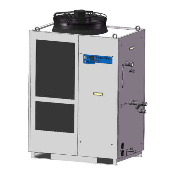
HRX-OM-S004 Chapter 2 Name and Function of Parts 2.2 Name and Function of Parts 2.2.1 HRS100/150-A-20/40/46 (In case of air cooled type) Fig. 2-2 Names of the parts (This drawing shows “HRS150-A-20”.) Table 2-1 Accessory list 2pcs. ① Alarm code list label (English 1pc. -
Page 17: Hrs100/150-W-20/40/46 (In Case Of Water Cooled Type)
HRX-OM-S004 Chapter 2 Name and Function of Parts 2.2.2 HRS100/150-W-20/40/46 (In case of water cooled type) Fig. 2-3 Names of the parts (This drawing shows “HRS150-W-20”.) Table 2-2 Accessory list 2pcs. ① Alarm code list label (English 1pc. /Japanese 1pc.) 2 Copies ②... -
Page 18: Function Of Parts
HRX-OM-S004 Chapter 2 Name and Function of Parts 2.3 Function of Parts The function of parts is as follows. Table 2-3 Function of parts Name Function Runs and stops the product and performs settings such as the circulating Operation display panel fluid temperature. -
Page 19: Operation Display Panel
HRX-OM-S004 Chapter 2 Name and Function of Parts 2.4 Operation display panel The operation panel on the front of the product controls the basic operation of the product. Fig. 2-4 Operation display panel Table 2-4 Operation display panel Reference Description Function page Displays the temperature and pressure of the circulating... - Page 20 HRX-OM-S004 Chapter 2 Name and Function of Parts 2.4 Operation display panel HRS Series...
-
Page 21: Chapter 3 Transport And Setting Up
HRX-OM-S004 Chapter 3 Transport and Setting Up Chapter 3 Transport and Setting Up Only persons who have sufficient knowledge and experience about the product and system are allowed to transport and set up the product. Especially pay attention to personal safety. 3.1 Transport The product is heavy and has potential danger at transport. -
Page 22: Transportation Using Forklift And Hanging
HRX-OM-S004 Chapter 3 Transport and Setting Up 3.1.1 Transportation using forklift and hanging The product are heavy object. (Refer to Table 3-1 Weight of the product) Moving by forklift and slinging should be done by persons who have the licenses. Fig 3-1 Fork inserting and hanging position (This drawing is [HRS150-A-20].) Table 3-1 Weight of the product Model... -
Page 23: Transportation Using Casters
HRX-OM-S004 Chapter 3 Transport and Setting Up 3.1.2 Transportation using casters <In case of purchasing the optional accessories, “Caster Adjuster-foot kit” (HRS-KS001 KS002) separately and after fastening it to the product.> This is a heavy object. (Refer to Table 3-1 Weight of the product). ... -
Page 24: Installation
HRX-OM-S004 Chapter 3 Transport and Setting Up 3.2 Installation Do not set up the product in places possibly exposed to leakage of flammable gas. Should any flammable gas stay around the product, the product may cause a fire. Keep the product uplight on a rigid and flat floor which can resist the weight of the product, and take measures to prevent the product from tipping over. - Page 25 HRX-OM-S004 Chapter 3 Transport and Setting Up Location that is subjected to static electricity, or conditions where static electricity can discharge to the product. Location that is subjected to strong high frequencies raditation (microwaves). Location that is subjected to potential lightening srtike. ...
-
Page 26: Location
HRX-OM-S004 Chapter 3 Transport and Setting Up 3.2.2 Location Do not install in a location which can be subjected to any of the conditions in 3.2.1 Environment. The air cooled product radiates heat from the air vent of the cooling fan. If the product is operated with insufficient air ventilation the internal ... - Page 27 HRX-OM-S004 Chapter 3 Transport and Setting Up The water cooled product radiates heat to the facility water. It is necessary to supply the facility water. Please prepare the facility water system that satisfies the heat radiation and the facility water specifications below.
-
Page 28: Installation And Maintenance Space
HRX-OM-S004 Chapter 3 Transport and Setting Up 3.2.3 Installation and Maintenance Space It is recommended to keep the space around the product shown in 3-3. Fig. Have an enough space for the ventilation for the product. Otherwise it may cause a lack of cooling capacity or/and stoppage of the product. Have an enough space for maintenance. -
Page 29: Installation
HRX-OM-S004 Chapter 3 Transport and Setting Up 3.3 Installation 3.3.1 Installation Install the product on the horizontal floor. Prepare the M10 anchor bolts that are appropriate to the material of the floor that the product will be installed. Drive the anchor bolts at least at two places of the left and right side of the product (four places in total). - Page 30 HRX-OM-S004 Chapter 3 Transport and Setting Up 〈In case of purchasing option A or [Caster Adjuster-foot kit] (HRS-KS002/KS003)〉 In case of using [Caster Adjuster-foot kit], be sure to use the adjuster foot to install on the floor. The adjuster foot is not earthquake-proof. Make an earthquake-resistant measure by the customer side.
-
Page 31: Electrical Wiring
HRX-OM-S004 Chapter 3 Transport and Setting Up 3.3.2 Electrical wiring Do not modify the intenal electrical wiring of the product. Incorrect wiring may cause electrical shock or fire. Also, modifing the internal wiring will void the product’s warranty. NEVER connect the ground to water line, gas pipe or lightening conductor. - Page 32 HRX-OM-S004 Chapter 3 Transport and Setting Up Power supply specifications, power supply cable and earth leakage breaker Prepare the power supply shown in the following table. For the connection between the product and power supply, use the power supply cable and earth leakage breaker shown below.
-
Page 33: Preparation And Wiring Of Power Supply Cable
HRX-OM-S004 Chapter 3 Transport and Setting Up 3.3.3 Preparation and wiring of power supply cable The electrical facilities should be installed and wired in accordance with local laws and regulations of each country and by a person who has knowledge and experience. ... - Page 34 HRX-OM-S004 Chapter 3 Transport and Setting Up In case of option B [Earth leakage breaker], option B [Earth leakage breaker with handle],HRS--40/46- A breaker that has the operating characteristic below is installed. Please use a breaker that has the same or longer operating time as/than this for the user’s side (primary side).
- Page 35 HRX-OM-S004 Chapter 3 Transport and Setting Up Preparation for operation Remove four screws to remove the front panel for the electrical unit. Fig. 3-6 Remove the front panel for the electrical unit (This drawing shows air cooled type.) Fig. 3-7 Remove the front panel for the electrical unit (This drawing shows water cooled type.) HRS Series 3.3Installation 3-15...
- Page 36 HRX-OM-S004 Chapter 3 Transport and Setting Up Hold the handle and put up the front panel of the electrical unit, and remove it. Fig. 3-8 Remove the front panel of the electrical unit (This drawing shows air cooled type.) Fig. 3-9 Remove the front panel of the electrical unit (This drawing shows water cooled type.) 3.3 Installation HRS Series 3-16...
- Page 37 HRX-OM-S004 Chapter 3 Transport and Setting Up Connect the power supply and the ground cable as shown in the figure below. Fig. 3-10 Wiring of power supply cable Connect over current protection to the user’s side (primary side) to avoid hazard. HRS Series 3.3Installation 3-17...
-
Page 38: Contact Input/Output Communicatin Wiring
HRX-OM-S004 Chapter 3 Transport and Setting Up 3.3.4 Contact input/output communicatin wiring Be sure to lock out and tag out the breaker of the facility power supply (customer power supply facility) before wiring. Use the cable and terminal that are specified. The capacity of the output contact of the product is limited. -
Page 39: Wiring Of Run/Stop Signal Input・Remote Signal Input
HRX-OM-S004 Chapter 3 Transport and Setting Up 3.3.5 Wiring of run/stop signal input・Remote signal input Run/Stop signal input and remote signal input enable the product to operate/stop or switched DIO REMOTE and DIO LOCAL remotely by applying a contact signal input. This chapter illustrates examples of wiring. Select DIO mode as the communication mode to activate the run/stop signal input and remote signal input after wiring referring to Operation Manual Communication Function. - Page 40 HRX-OM-S004 Chapter 3 Transport and Setting Up Connect the signal cable and switch to the terminal as follows. (This wiring is an example.) Terminal No. 5 Terminal No.13 Terminal No. 3 Terminal No.11 Fig. 3-11 Wiring of Run/stop signal input・Remote signal input (Example) inal No.
-
Page 41: Wiring Of External Switch Signal Input
HRX-OM-S004 Chapter 3 Transport and Setting Up 3.3.6 Wiring of external switch signal input This product can be monitored by sampling the signal of the external switch prepared by the customer. Table 3-7 Power supply, contact specifications Name Terminal NO. Specification 5, 6, 7 (24VDC) ... - Page 42 HRX-OM-S004 Chapter 3 Transport and Setting Up Prepare the flow switch described in the table purchasing separately. Depending on the external switch output type, connect the wire the switch to the terminals for contact input signal as shown below. (This is an example of wiring. Refer to the Operation Manual Communication Function for further details.) Flow switch Blue(DC COM)
- Page 43 HRX-OM-S004 Chapter 3 Transport and Setting Up Setting items Table 3-10 shows the setting items of the external switch. For details, refer to 5.21 Communication function. Table 3-10 Setting list of the external switch Initial value Reference Display Item Category Example...
-
Page 44: Wiring Of Contact Output Signal
HRX-OM-S004 Chapter 3 Transport and Setting Up 3.3.7 Wiring of contact output signal Contact output signals are the signals that output the status of this product. Contact specification of each signal output is shown below Be sure to turn OFF the breaker of the facility power supply (the user's machine power supply) before wiring. -
Page 45: Communication Wiring
HRX-OM-S004 Chapter 3 Transport and Setting Up 3.3.8 RS-485 communication wiring Serial communication RS-485, operation start/stop, setting and reading of circulating fluid temperature, and reading of alarm condition can be done by remote control. Refer to the Operation Manual Communication Function for more details. ... -
Page 46: Rs-232C Communication Wiring
HRX-OM-S004 Chapter 3 Transport and Setting Up 3.3.9 RS-232C communication wiring Serial communication RS-232C, operation start/stop, setting and reading of circulating fluid temperature, and reading of alarm condition can be performed by remote control. Refer to the Communications Operation Manual for more details. ... -
Page 47: Piping
HRX-OM-S004 Chapter 3 Transport and Setting Up 3.4 Piping Connect piping firmly. Incorrect piping might cause leakage of supplied or drained fluid and wet surrounding area and facility. Use caution not to allow dust and foreign matter to enter the water circuit, etc. - Page 48 HRX-OM-S004 Chapter 3 Transport and Setting Up How to connect piping Tighten the piping to each connection as follows below. Fig. 3-16 Tightening of piping How to connect to the drain port When piping the pump drain port, hold the ball valve of the pump drain port with a wrench not to rotate it.
- Page 49 HRX-OM-S004 Chapter 3 Transport and Setting Up Recommended piping circuit Fig. 3-18 Recommended piping circuit HRS Series 3.4Piping 3-29...
- Page 50 HRX-OM-S004 Chapter 3 Transport and Setting Up Install the drain pan for the pump This product uses the pump that uses mechanical seal. Install the of accessory under the pump. If the leakage is found, replace the mechanical seal. Order the mechanical seal described in “7.3 Consumables”...
-
Page 51: Circulating Fluid Supply
HRX-OM-S004 Chapter 3 Transport and Setting Up 3.5 Circulating Fluid Supply 3.5.1 Automatic fluid-fill function When tap water is used, refer to “7.1Quality Control of Circulating Fluid and Facility Water”. When 15% ethylene glycol aqueous solution is used, dilute pure ethylene glycol with water. - Page 52 HRX-OM-S004 Chapter 3 Transport and Setting Up 15% aqueous solution of ethylene glycol When a 15% aqueous solution of ethylene glycol is used, prepare the ethylene glycol aqueous solution separately. To control the density of the ethylene glycol aqueous solution, a densitometer is available (sold separately) from SMC.
-
Page 53: Fill Of Fluid Without Using Auto Fluid-Fill Function
HRX-OM-S004 Chapter 3 Transport and Setting Up 3.5.2 Fill of fluid without using auto fluid-fill function To supply the circulating fluid without using automatic fluid-fill function, remove the upper panel on the right side, and supply the fluid to the fluid-fill port on top of the tank. Remove the screws (7 pcs.) to remove upper panel on the right side. - Page 54 HRX-OM-S004 Chapter 3 Transport and Setting Up Supply the circulating fluid to the water fill port. Confirm that the fluid level is between “HIGH” and “LOW” levels of the fluid level gauge. If it exceeds the specified level, the circulating fluid will overflow.
-
Page 55: For Option K "Fluid-Fill Port
HRX-OM-S004 Chapter 3 Transport and Setting Up For option K “Fluid-fill port” 3.5.3 Confirm that the fluid level is between “HIGH” and “LOW” levels of the fluid level gauge. If it exceeds the specified level, the circulating fluid will overflow. ... - Page 56 HRX-OM-S004 Chapter 3 Transport and Setting Up 3.5 Circulating Fluid Supply HRS Series 3-36...
-
Page 57: Chapter 4 Starting The Product
HRX-OM-S004 Chapter 4 Starting the Product Chapter 4 Starting the Product Only people who have sufficient knowledge and experience about the product and its accessories are allowed to start and stop the product. 4.1 Before Starting Check the following points before starting the product. ... -
Page 58: Preparation For Start
HRX-OM-S004 Chapter 4 Starting the Product 4.2 Preparation for Start 4.2.1 Power supply Turn ON the breaker of the user’s power supply. When the product is switched ON, the operation panel display operates as shown below: The initial screen (HELLO screen) is displayed for 8 seconds on the operation display panel. -
Page 59: For Hrs100/150-**-20-B1,Hrs100/150-**-40/46
HRX-OM-S004 Chapter 4 Starting the Product 4.2.3 For HRS100/150-**-20-B1,HRS100/150-**-40/46 Turn on the breaker handle. The status will become the clause 4.2.1 Power supply. Fig. 4-2 Position of the breaker handle (This drawing shows “HRS150-A-40”.) 4.2.4 Setting of circulating fluid temperature Press the [▼] or [▲] button on the operation panel to change the SV to the required value. -
Page 60: Preparation Of Circulating Fluid
HRX-OM-S004 Chapter 4 Starting the Product 4.3 Preparation of circulating fluid Circulating fluid is supplied only inside of the product at the time of installation of the thermo-chiller. When the product starts operation in this condition, circulating fluid level will be reduced as the fluid in the level gauge goes down due to the fluid supply to the user's equipment from the thermo-chiller, and the additional fluid needs to be supplied to the thermo-chiller. - Page 61 HRX-OM-S004 Chapter 4 Starting the Product Press the [RESET] button (press the [▼] and [▲] buttons simultaneously) to stop the alarm buzzer. Flash Press together Fig. 4-6 Alarm receipt Reset alarms on the ”Alarm menu” screen. Alarm reset is not accepted from any screen except the "Alarm menu"...
- Page 62 HRX-OM-S004 Chapter 4 Starting the Product Press the [RESET] button (press the [▼] and [▲] buttons simultaneously) to reset the alarm. Pressing these buttons at the same time resets the alarm (low level in tank) and turns OFF the [ALARM] LED (red) and the [ ] LED.
-
Page 63: Operation Start And Stop
HRX-OM-S004 Chapter 4 Starting the Product 4.4 Operation Start and Stop 4.4.1 Starting the product Allow at least five minutes before restarting the product. Before starting, check the items specified in “4.1 Before Starting” If any alarm light remains ON, refer to Chapter 6 Alarm Notification and Troubleshooting”... -
Page 64: Stopping The Product
HRX-OM-S004 Chapter 4 Starting the Product 4.4.2 Stopping the product Press the [RUN/STOP] button on the operation panel. The [RUN] light on the operation panel blinks green at 1 second intervals, and continues operation to prepare to stop. After approximately 20 seconds, the [RUN] light turns OFF and the operation stops completely. -
Page 65: Check Items During Startup
HRX-OM-S004 Chapter 4 Starting the Product 4.5 Check items during startup Check the following items after starting the product. When any abnormality is found, press the [STOP] button to stop the product operation, and then turn OFF the breaker of the user’s power supply. - Page 66 HRX-OM-S004 Chapter 4 Starting the Product 4.6 Adjustment of Circulating Fluid flow rate HRS Series 4-10...
-
Page 67: Chapter 5 Display And Setting Of Various Functions
HRX-OM-S004 Chapter 5 Display and setting of various functions Chapter 5 Display and setting of various functions Read and understand this manual carefully before changing the settings. 5.1 List of function The product can have the displays and settings shown in Table 5-1. Table 5-1 List of function Reference Function... -
Page 68: Function
HRX-OM-S004 Chapter 5 Display and setting of various functions 5.2 Function 5.2.1 Key operations Fig. “Key operation (1/2)” and “Key operation (2/2)” shows the operation of keys of the thermo-chiller. By pressing the “SEL” key for 2 seconds, the PV display blinks and function of “SEL”... - Page 69 HRX-OM-S004 Chapter 5 Display and setting of various functions MENU MENU MENU Alarm setting Communication menu setting menu Contact input Unused Alarm Communicati signal 1 Delay buzzer on mode MENU MENU timer (time sound Press the Press the delay) of 2 sec.
-
Page 70: List Of Parameters
HRX-OM-S004 Chapter 5 Display and setting of various functions 5.2.2 List of parameters “Table 5.2-1 List of parameters (1/3)” to “ ” Table 5.2-3 List of parameter (3/3) show the parameters of the thermo-chiller. Table 5.2-1 List of parameters (1/3) Reference Display Content... - Page 71 HRX-OM-S004 Chapter 5 Display and setting of various functions Table 5.2-2 List of parameter (2/3) Reference Display Content Category Default setting4 page Warming up function 5.17 ---- Setting Warming up temperature setting C (68.0 ゚ F)6 (20.0 menu Anti-snow coverage function 5.18 Dust-proof filter accumulated time reset 5.16...
- Page 72 HRX-OM-S004 Chapter 5 Display and setting of various functions Table 5.2-3 List of parameter (3/3) Reference Display Content Default setting Category page Changing of circulating fluid pressure A.STP sensor error Changing of the pump maintenance A.STP Changing of the fan maintenance Alarm setting Changing compressor...
-
Page 73: Main Display
HRX-OM-S004 Chapter 5 Display and setting of various functions 5.3 Main Display 5.3.1 Main Display The current temperature and the set temperature of the circulating fluid are shown on the main display, and the main display allows the set temperature to be changed. -
Page 74: Alarm Menu
HRX-OM-S004 Chapter 5 Display and setting of various functions Alarm Menu 5.4.1 Alarm menu The alarm display appears when an alarm is generated. The alarm menu is not be accessible when no alarm has been generated. Refer to “Chapter 6 Alarm Notification and Troubleshooting” for details of alarms. -
Page 75: Check Monitor Menu
HRX-OM-S004 Chapter 5 Display and setting of various functions 5.5 Check monitor menu 5.5.1 Check monitor menu As a part of the daily inspection, the temperature, pressure and accumulated operating time can be checked. Please use this for confirmation of your daily inspection. 5.5.2 Checking with the Inspection monitor menu The table below explains the check items of the inspection monitor menu. - Page 76 HRX-OM-S004 Chapter 5 Display and setting of various functions Checking: Circulating fluid temperature at the heat exchanger inlet Press the [SEL] key once. Display of the circulating fluid temperature returned to the return port appears on the digital display. Displays the circulating fluid temperature returning from the user’s equipment. Check of the temperature of the inlet of the compressor.
- Page 77 HRX-OM-S004 Chapter 5 Display and setting of various functions Checking: Refrigerant circuit pressure on the low pressure side Press the [SEL] key once. Display of the refrigerant circuit pressure on the low pressure side appears on the digital display. Checking: Accumulated operating time of the pump Press the [SEL] key once.
- Page 78 HRX-OM-S004 Chapter 5 Display and setting of various functions Checking: Accumulated operating time of the compressor Press the [SEL] key once. Display of the accumulated operating time of the compressor appears on the digital display. Refer to “ Table 5.5-2 ” for the display. AL30 Compressor maintenance alarm is generated when the accumulated operating ) (when set to “A.RUN”).
-
Page 79: Key-Lock
HRX-OM-S004 Chapter 5 Display and setting of various functions 5.6 Key-lock 5.6.1 Key-lock The buttons can be locked to prevent the settings being changed by an operator error. Operation can be started/stopped by operating the “RUN/STOP” key even when the button-lock is being activated. If you try to change the set value with the “▲”... -
Page 80: Key-Lock
HRX-OM-S004 Chapter 5 Display and setting of various functions 5.6.2 Key-lock setting / checking The table below explains the setting items of the key-lock function and the initial values. Table 5.6-1 Set items for key -lock Display Item Contents Default Sets the -lock function ON. -
Page 81: Run Timer, Stop Timer Function
HRX-OM-S004 Chapter 5 Display and setting of various functions 5.7 Run timer, stop timer function 5.7.1 Run timer and stop timer function This function starts or stops operation of the product automatically when the set time has passed. The time can be set according to the user’s working hours. - Page 82 HRX-OM-S004 Chapter 5 Display and setting of various functions Timer setting example Run timer Set to start after 3hours ・・・ Stopped Operating ↑Operating Stop timer Set to stop after 3 hours ・・・ Operating Stopped ↑Stopped Run timer Stop timer Set to start after 2 hours ・・・...
-
Page 83: Setting And Checking Of Run Timer And Stop Timer Function
HRX-OM-S004 Chapter 5 Display and setting of various functions 5.7.2 Setting and checking of Run timer and stop timer function The table below explains the setting items of the run/stop timer and the initial values. Table 5.7-1 Setting of run timer and stop timer Display Item Contents... - Page 84 HRX-OM-S004 Chapter 5 Display and setting of various functions Setting/checking: Stop timer Press the [SEL] key once. Setting screen of the stop timer appears on the digital display. Select stop timer with the [▲] key or the [▼] key, and press [SEL] key to enter. Table 5.7-3 Setting of the stop timer Set value Explanation...
-
Page 85: Ready Completion (Temp Ready) Signal
HRX-OM-S004 Chapter 5 Display and setting of various functions 5.8 Ready completion (TEMP READY) signal 5.8.1 Ready completion (TEMP READY) signal This function sets a bandwidth for the set circulating fluid temperature (range between the upper and lower limit temperatures) to notify the user by communication that the circulating fluid temperature has reached the band range. -
Page 86: Ready Completion (Temp Ready) Signal Setting / Checking
HRX-OM-S004 Chapter 5 Display and setting of various functions 5.8.2 Ready completion (TEMP READY) signal setting / checking The table below shows explanation and default of the set items for ready completion (TEMP READY) signal. Table 5.8-1 Set items for ready completion (TEMP READY) signal Display Item Content... - Page 87 HRX-OM-S004 Chapter 5 Display and setting of various functions Select READY bandwidth with [▲] key or [▼] key, and enter by pressing the [SEL] key. Table 5.8-3 Set value for READY mode Set value Explanation Default Sets READY bandwidth (range between the upper and lower limit temperatures) for the set circulating fluid temperature.
-
Page 88: Offset Function
HRX-OM-S004 Chapter 5 Display and setting of various functions 5.9 Offset function 5.9.1 Offset function This is a function that controls the "circulating fluid display temperature" and the "target temperature for chiller temperature control" by shifting the temperature for the set offset value. This product has three different modes of offset functions (MODE 1 to 3). -
Page 89: Usage Example Of Offset Function
HRX-OM-S004 Chapter 5 Display and setting of various functions 5.9.2 Usage example of offset function Suppose that the circulating fluid discharge temperature of this thermo-chiller is 30 C and the circulating fluid temperature that enters the user's equipment is 29 C due to temperature drop while it is transferred to the user's equipment in the piping: This product... -
Page 90: Offset Temperature
HRX-OM-S004 Chapter 5 Display and setting of various functions ■ When only the "displayed circulating fluid temperature" needs to be the same as the circulating temperature supplied to the user's equipment: Use "MODE 2" of the offset function, and set the offset temperature to "-1.0" 1. -
Page 91: Setting/Checking Of Offset Function
HRX-OM-S004 Chapter 5 Display and setting of various functions 5.9.3 Setting/checking of offset function The table below shows the set items of the offset function and the default values. Table 5.9-2 Set items for offset function Display Item Contents Default Offset mode Offset mode is set ON/OFF. - Page 92 HRX-OM-S004 Chapter 5 Display and setting of various functions Setting/Checking: Offset temperature Press the [SEL] key once. Setting screen of offset temperature appears on the digital display. Set offset temperature with [▲] key or [▼] key, and press [SEL] key to enter. Table 5.9-4 Offset temperature setting Set value Explanation...
-
Page 93: Operation Restoration After Power Failure
HRX-OM-S004 Chapter 5 Display and setting of various functions 5.10 Operation Restoration after Power Failure 5.10.1 Operation restoration function after power failure When the power supply is cut due to power failure, etc., this function restarts the operation when the power supply restores, retaining the conditions before the power cut. -
Page 94: Setting/Checking Of The Operation Restoration Function
HRX-OM-S004 Chapter 5 Display and setting of various functions 5.10.2 Setting/checking of the operation restoration function The table below shows the setting items of the operation restoration after power failure function and the default setting. Table 5.10-1 Set item for operation restoration after power failure function Display Item Contents... -
Page 95: Anti-Freezing Function
HRX-OM-S004 Chapter 5 Display and setting of various functions 5.11 Anti-freezing function 5.11.1 Anti-freezing function Keep the power supply ON for this function. This function does not start when the power is OFF. This function prevents freezing of the circulating fluid while the product stops operation in the winter season with heat generated by automatically operating the pump. - Page 96 HRX-OM-S004 Chapter 5 Display and setting of various functions This function can be activated only when the power supply is ON and the thermo-chiller is not operating. Fully open the valve or manual bypass valve that is arranged by the user to make it possible for the circulating fluid to circulate when the pump starts automatic operation.
-
Page 97: Anti-Freezing Function
HRX-OM-S004 Chapter 5 Display and setting of various functions 5.11.2 Setting/checking of anti-freezing function The table below shows the set item of the anti-freezing function and the default setting. Table 5.11-1 Set item for anti-freezing function Display Item Contents Default Anti-freezing Sets anti-freezing function ON/OFF. -
Page 98: Key Operation Sound Setting
HRX-OM-S004 Chapter 5 Display and setting of various functions 5.12 Key Operation Sound Setting 5.12.1 Key operation sound setting Operation sound (click sound) of the buttons on the operation panel can be set ON/OFF. Default setting is button operation sound “ON”. 5.12.2 Setting/checking of the button operation sound The table below shows the set item for button operation sound and the default setting. -
Page 99: Temperature Unit Change
HRX-OM-S004 Chapter 5 Display and setting of various functions 5.13 Temperature unit Change 5.13.1 Temperature unit change The temperature unit used for the thermo-chiller can be selected Celsius C) or Fahrenheit ( F). This setting determines the temperature unit which is displayed/output. -
Page 100: Pressure Unit Change
HRX-OM-S004 Chapter 5 Display and setting of various functions 5.14 Pressure unit Change 5.14.1 Pressure unit change Pressure unit used for the thermo-chiller can be selected MPa or PSI. This setting determines the pressure unit which is displayed/output. The default setting is MPa. -
Page 101: Data Reset Function
HRX-OM-S004 Chapter 5 Display and setting of various functions 5.15 Data reset function 5.15.1 Data reset function Resets the values set by user to the default values. Note that the accumulated operating time will not be reset. This function resets all the set values. Use caution when operating this function. -
Page 102: Accumulated Operating Time Reset Function
HRX-OM-S004 Chapter 5 Display and setting of various functions 5.16 Accumulated Operating Time Reset Function 5.16.1 Accumulated operating time reset function The alarms shown below will be generated to notify the maintenance timing. The thermo-chiller does not stop operation for these alarms. ... - Page 103 HRX-OM-S004 Chapter 5 Display and setting of various functions Press the [SEL] key 14 times. Resetting screen of the pump accumulated operating time appears on the digital display. Select with [▲] key or [▼] key, and press [SEL] key to enter. Select and press [SEL] key to enter, and the accumulated operating time of the pump will be reset.
- Page 104 HRX-OM-S004 Chapter 5 Display and setting of various functions Reset of accumulated operating time Press and hold the [MENU] key for approximately 2 seconds. Repeat pressing the key until the button-lock setting screen [ ] appears on the digital display. Press and Press and hold [MENU]...
- Page 105 HRX-OM-S004 Chapter 5 Display and setting of various functions Reset of the accumulated operating time of the dust-proof filter Press and hold the [MENU] key for approximately 2 seconds. Repeat pressing the key until the button-lock setting screen [ ] appears on the digital display.
-
Page 106: Warming Up Function
HRX-OM-S004 Chapter 5 Display and setting of various functions 5.17 Warming up function 5.17.1 Warming up function Keep the power supply ON for this function. This function does not operate when the power is OFF. This function maintains the circulating fluid temperature to the set warming-up temperature with heat generated by automatically operating the pump in the winter season or at night. -
Page 107: Warming Up Function
HRX-OM-S004 Chapter 5 Display and setting of various functions 5.17.2 Setting/checking of warming up function The table below shows the setting items of the warming up function and the default setting. Table 5.17-1 Set item for warming up function Initial value Display Item Content... - Page 108 HRX-OM-S004 Chapter 5 Display and setting of various functions Set the warming up temperature with [▲] key or [▼] key, and press [SEL] key to enter. Table 5.17-3 Setting of warming up temperature Initial value Set value Explanation (Default setting) Setting and checking are not available when the warming up function is set OFF.
-
Page 109: Anti-Snow Coverage Function
HRX-OM-S004 Chapter 5 Display and setting of various functions 5.18 Anti-snow coverage function 5.18.1 Anti-snow coverage function Keep the power supply ON for this function. This function does not operate when the power is OFF. This function does not operate for water-cooled type. This function prevents snow coverage on the exhaust port on top of the product during the winter time by automatically operating the fan periodically. -
Page 110: Anti-Snow Coverage Function
HRX-OM-S004 Chapter 5 Display and setting of various functions 5.18.2 Setting/checking of anti-snow coverage function The table below shows the set item of the anti-snow coverage function and the default setting. Table 5.18-1 Set item for anti-snow coverage function Initial value Display Item Content... -
Page 111: Alarm Buzzer Sound Setting
HRX-OM-S004 Chapter 5 Display and setting of various functions 5.19 Alarm buzzer sound setting 5.19.1 Alarm buzzer sound setting This sets whether a warning sound is made or not when alarm signal is output. The default setting is buzzer sound ON. 5.19.2 Setting/checking of alarm buzzer sound The table below shows the set item of the alarm buzzer sound and the default setting. -
Page 112: Alarm Customizing Function
HRX-OM-S004 Chapter 5 Display and setting of various functions 5.20 Alarm customizing function 5.20.1 Alarm customizing function Operation and trigger level when an alarm signal is output can be customized. Perform settings depending on the application of the user. Refer to “Table 5.16-1 Accumulated operating time to be reset” and “Table 5.16-2 Resetting of accumulated operating time of the fan”... -
Page 113: Alarm Customizing Function
HRX-OM-S004 Chapter 5 Display and setting of various functions Table 5.20-2 Alarm setting and customizing (2/4) ①Alarm operations ②Alarm threshold and others Code Alarm name Default Display Display Settable range setting Set temperature 1.0~34.0 (33.8 (33.8~93.2 5 (----) Monitoring method Circulating fluid 0~3... - Page 114 HRX-OM-S004 Chapter 5 Display and setting of various functions Table 5.20-3 Alarm setting and customizing (2/4) ①Alarm operations ②Alarm threshold and others Code Alarm name Default Settable Display Display setting range Refrigerant circuit ● ○ pressure (low AL17 pressure side) drop Compressor running ●...
- Page 115 HRX-OM-S004 Chapter 5 Display and setting of various functions Table 5.20-4 Alarm setting and customizing (2/4) ①Alarm operations ②Alarm threshold and others Code Alarm name Default Settable Display Display setting range Dust-proof filter ○ ● AL40 maintenance ○ ● AL41 Power stoppage ○...
-
Page 116: Setting And Checking Of The Alarm Customizing Function
HRX-OM-S004 Chapter 5 Display and setting of various functions 5.20.2 Setting and checking of the alarm customizing function The table below shows the set items of the alarm customizing function and the default settings. Table 5.20-5 Default settings of the alarm customizing function (1/3) Default Object alarm Display... - Page 117 HRX-OM-S004 Chapter 5 Display and setting of various functions Table 5.20-6 Default settings of the alarm customizing function (2/3) Object alarm Default Display Content Change content setting Code Alarm name Product operation Operation setting when AL21 while the alarm is A.STP "DC line fuse cut"...
- Page 118 HRX-OM-S004 Chapter 5 Display and setting of various functions Table 5.20-7 Default settings of the alarm customizing function (3/3) Object alarm Initial Display Content Change content setting Code Alarm name Operation setting when Circulating fluid "Circulating fluid Product operation discharge pressure discharge pressure AL25 while the alarm is...
- Page 119 HRX-OM-S004 Chapter 5 Display and setting of various functions Press and hold the [MENU] key for approximately 2 seconds. Repeat pressing the key until the alarm buzzer sound setting screen [ ] appears on the digital display. Press and Press and Press and hold hold...
- Page 120 HRX-OM-S004 Chapter 5 Display and setting of various functions Operation continues when this alarm signal is ✓ generated. Operation is stopped when this alarm signal is generated. 5.20 Alarm customizing function HRS Series 5-54...
- Page 121 HRX-OM-S004 Chapter 5 Display and setting of various functions Setting/Checking: Threshold temperature setting for "Detection temp. for the circulating fluid discharge temp. increase" alarm Press the [SEL] key once. Threshold detecting temperature setting screen for "Circulating fluid discharge temp. rise" alarm generation appears on the digital display. Set the threshold detection temperature for "Circulating fluid discharge temp.
- Page 122 HRX-OM-S004 Chapter 5 Display and setting of various functions Setting/Checking: Threshold detecting temperature setting for "Circulating fluid discharge temp. drop" alarm generation Press the [SEL] key once. Threshold detecting temperature setting screen for "Circulating fluid discharge temp. drop" alarm generation appears on the digital display. Set the threshold detecting temperature for "Circulating fluid discharge temp.
- Page 123 HRX-OM-S004 Chapter 5 Display and setting of various functions Setting/Checking: Threshold pressure setting for "Circulating fluid discharge pressure rise" alarm Press the [SEL] key once. Threshold detecting pressure setting screen for "Circulating fluid discharge pressure rise" alarm generation appears on the digital display. Set the threshold detection pressure for "Circulating fluid discharge pressure rise"...
- Page 124 HRX-OM-S004 Chapter 5 Display and setting of various functions Set the product operation when "Circulating fluid discharge pressure drop" alarm is generated with [▲] key or [▼] key, and press [SEL] key to enter. Table 5.20-15 Operation setting when "Circulating fluid discharge pressure drop" alarm is generated Initial value Set value Explanation...
- Page 125 HRX-OM-S004 Chapter 5 Display and setting of various functions Setting/Checking: Operation setting when "Communication error" alarm is generated Press the [SEL] key once. Operation setting screen when "Communication error" alarm is generated appears on the digital display. Set operation when "Communication error" alarm is generated with [▲] key or [▼] key, and press [SEL] key to enter.
- Page 126 HRX-OM-S004 Chapter 5 Display and setting of various functions Set the product operation when "Contact input 1 signal detection" alarm is generated with [▲] key or [▼] key, and press [SEL] key to enter. Table 5.20-19 Operation setting when "Contact input 1 signal detection" alarm is generated Initial value Set value Explanation...
- Page 127 HRX-OM-S004 Chapter 5 Display and setting of various functions Set the product operation when "DC line fuse cut" alarm is generated with [▲] key or [▼] key, and press [SEL] key to enter. Table 5.20-21 Operation setting when "DC line fuse cut" alarm is generated Initial value Set value Explanation...
- Page 128 HRX-OM-S004 Chapter 5 Display and setting of various functions Setting/Checking: Monitoring start timer Press the [SEL] key once. Setting screen of the monitoring start timer is displayed on the digital display. Set monitoring start timer with the [▲] key or the [▼] key, and press [SEL] key to enter. Table 5.20-23 Setting of the monitoring start timer Initial value Set value...
-
Page 129: Setting Of Temperature Alarm Monitoring Method And Alarm Generation Timing
HRX-OM-S004 Chapter 5 Display and setting of various functions 5.20.3 Setting of temperature alarm monitoring method and alarm generation timing Examples of temperature alarm monitoring method setting and alarm generation timing are shown below. When "Automatic monitoring" is selected [1] Circulating fluid temperature when starting operation: Approximately 20 Circulating fluid set temperature : 15... - Page 130 HRX-OM-S004 Chapter 5 Display and setting of various functions When "Automatic monitoring + Monitoring start timer" is selected [1] Circulating fluid temperature when starting operation: Approximately 20 Circulating fluid set temperature : 15 [3] "AS.21: Temperature alarm monitoring method": Select "Automatic monitoring + Monitoring start timer".
- Page 131 HRX-OM-S004 Chapter 5 Display and setting of various functions Setting/Checking: Operation when compressor related alarms are generated Press the [SEL] key once. Setting screen of the product operation when compressor related alarms are generated appears on the digital display. Set the product operation when the compressor related errors are generated with the [▲] key or [▼] key.
- Page 132 HRX-OM-S004 Chapter 5 Display and setting of various functions Setting/Checking: Operation setting when "Circulating fluid discharge pressure sensor error" alarm is generated Press the [SEL] key once. Operation setting screen when "Circulating fluid discharge pressure sensor failure" alarm is generated appears on the digital display. Set the product operation when "Circulating fluid discharge pressure sensor failure"...
- Page 133 HRX-OM-S004 Chapter 5 Display and setting of various functions Setting/Checking: Operation setting when "Fan maintenance" alarm is generated Press the [SEL] key once. Operation setting screen when "Fan maintenance" alarm is generated appears on the digital display. Set the product operation when "Fan maintenance" alarm is generated with [▲] key or [▼] key, and press [SEL] key to enter.
- Page 134 HRX-OM-S004 Chapter 5 Display and setting of various functions Setting/Checking: Operation setting when "Dust-proof filter maintenance" alarm is generated Press the [SEL] key once. Operation setting screen when "Dust-proof filter maintenance" alarm is generated appears on the digital display. Set the product operation when "Dust-proof filter maintenance" alarm is generated with [▲] key or [▼] key, and press [SEL] key to enter.
- Page 135 HRX-OM-S004 Chapter 5 Display and setting of various functions Setting/Checking: Monitoring time for maintenance of dustproof filter Press the [SEL] key once. Setting screen of the monitoring time before "Dust-proof filter maintenance" alarm is generated is displayed on the digital display. Set the monitoring time before the "Dust-proof filter maintenance"...
-
Page 136: Setting/Checking Of Communication Function
HRX-OM-S004 Chapter 5 Display and setting of various functions 5.21 Communication function 5.21.1 Communication function Contact input/output and serial communication can be performed. Refer to the Operation Manual Communication Function for more details 5.21.2 Setting/checking of communication function The table below shows the set items of the communication function and default settings. - Page 137 HRX-OM-S004 Chapter 5 Display and setting of various functions Setting/Checking: Communication mode Press and hold the [MENU] key for approximately 2 seconds. Repeat pressing the button until the communication mode setting screen [ appears on the digital display. Press and Press and Press and hold [MENU]...
- Page 138 HRX-OM-S004 Chapter 5 Display and setting of various functions Select a serial communication protocol with [▲] key or [▼] key, and press [SEL] key to enter. Table 5.21-3 Setting of serial communication protocol Initial value Set value Explanation (Default setting) ✓...
- Page 139 HRX-OM-S004 Chapter 5 Display and setting of various functions Setting/Checking: Slave addresses (MODBUS) Press the [SEL] key once. Setting screen of slave addresses (MODBUS) is displayed on the digital display. Set slave addresses (MODBUS) with [▲] key or [▼] key, and press [SEL] key to enter. Table 5.21-6 Slave address settings Initial value Set value...
- Page 140 HRX-OM-S004 Chapter 5 Display and setting of various functions S Set slave addresses (simple communication protocol) with [▲] key or [▼] key, and press [SEL] key to enter. Table 5.21-8 Setting of slave addresses Initial value Set value Explanation (Default setting) Setting/checking is possible only when the serial protocol setting is simple communication protocol.
- Page 141 HRX-OM-S004 Chapter 5 Display and setting of various functions Set BCC (simple communication protocol) with [▲] key or [▼] key, and press [SEL] key to enter. Table 5.21-10 BCC setting Initial value Set value Explanation (Default setting) Setting/checking is possible only when the serial protocol setting is simple communication protocol.
- Page 142 HRX-OM-S004 Chapter 5 Display and setting of various functions Perform setting for parity check (simple communication protocol) with [▲] key or [▼] key, and press [SEL] key to enter. Table 5.21-12 Parity check setting Initial value Set value Explanation (Default setting) Setting/checking is possible only when the serial protocol...
- Page 143 HRX-OM-S004 Chapter 5 Display and setting of various functions Set responce delay time (simple communication protocol) with [▲] key or [▼] key, and press [SEL] key to enter. Table 5.21-14 Setting of response delay time Initial value Set value Explanation (Default setting) Setting/checking is possible only when the serial...
- Page 144 HRX-OM-S004 Chapter 5 Display and setting of various functions Perform setting for the contact input signal 1 with [▲] key or [▼] key, and press [SEL] key to enter. Table 5.21-16 Setting for contact input signal 1 Initial value Set value Explanation (Default setting) No signal input...
- Page 145 HRX-OM-S004 Chapter 5 Display and setting of various functions Set time delay for the contact input signal 1 delay timer for reading with [▲] key or [▼] key, and press [SEL] key to enter. Table 5.21-18 Setting of time delay for contact input signal delay timer for reading Initial value Set value Explanation...
- Page 146 HRX-OM-S004 Chapter 5 Display and setting of various functions Perform setting of the contact input signal 2 with [▲] key or [▼] key, and press [SEL] key to enter. Table 5.21-20 Setting of the contact input signal 2 Initial value Set value Explanation (Default setting)
- Page 147 HRX-OM-S004 Chapter 5 Display and setting of various functions Set time delay for the contact input signal 2 delay timer for reading with [▲] key or [▼] key, and press [SEL] key to enter. Table 5.21-22 Setting of time delay for the contact input signal 2 delay timer for reading Initial value Set value Explanation...
- Page 148 HRX-OM-S004 Chapter 5 Display and setting of various functions Select a function with [▲] key or [▼] key, and press [SEL] key to enter. Table 5.21-24 Setting for the contact output signal 1 Initial value Set value Explanation (Default setting) No signal output ✓...
- Page 149 HRX-OM-S004 Chapter 5 Display and setting of various functions Setting/Checking: Selected alarm for contact output signal 1 Press the [SEL] key once. Setting screen of selected alarm of the contact output signal 1 is displayed on the digital display. Set the alarm selected for the contact output signal 1 with [▲] key or [▼] key, and press [SEL] key to enter.
- Page 150 HRX-OM-S004 Chapter 5 Display and setting of various functions Select a function with [▲] key or [▼] key, and press [SEL] key to enter. Table 5.21-27 Setting for the contact output signal 2 Initial value Set value Explanation (Default setting) No signal output Operation status signal output ✓...
- Page 151 HRX-OM-S004 Chapter 5 Display and setting of various functions Setting/Checking: Selected alarm for contact output signal 2 Press the [SEL] key once. Setting screen of selected alarm of the contact output signal 2 is displayed on the digital display. Set the alarm selected for the contact output signal 2 with [▲] key or [▼] key, and press [SEL] key to enter.
- Page 152 HRX-OM-S004 Chapter 5 Display and setting of various functions Select a function for the contact output signal 3 with [▲] key or [▼] key, and press [SEL] key to enter. Table 5.21-30 Function setting for the contact output signal 3 Initial value Set value Explanation...
- Page 153 HRX-OM-S004 Chapter 5 Display and setting of various functions Setting/Checking: Selected alarm for contact output signal 3 Press the [SEL] key once. Setting screen of the selected alarm of the contact output signal 3 is displayed on the digital display. Set the alarm selected for the contact output signal 3 with [▲] key or [▼]key, and press [SEL] key to enter.
- Page 154 HRX-OM-S004 Chapter 5 Display and setting of various functions 5.21 Communication function HRS Series 5-88...
-
Page 155: Chapter 6 Alarm Notification And Troubleshooting
HRX-OM-S004 Chapter 6 Alarm Notification and Troubleshooting Chapter 6 Alarm Notification and Troubleshooting 6.1 Alarm Notification The product makes notification in the order shown below when any alarm is generated. The [ALARM] light blinks. The alarm buzzer sounds. ... - Page 156 HRX-OM-S004 Chapter 6 Alarm Notification and Troubleshooting When multiple alarms are generated, the alarm codes are displayed one by one by pressing the [SEL] button Alarm with the number ”1” in the SV window on the digital display is the latest alarm.
-
Page 157: Alarm Buzzer Stop
HRX-OM-S004 Chapter 6 Alarm Notification and Troubleshooting 6.2 Alarm buzzer stop An alarm buzzer sounds to notify when any alarms are generated. How to stop the alarm buzzer is explained below. Confirm that the alarm display is shown. The alarm buzzer can be stopped only on this screen. -
Page 158: Troubleshooting
HRX-OM-S004 Chapter 6 Alarm Notification and Troubleshooting 6.3 Troubleshooting 6.3.1 Alarm contents, causes, and troubleshooting Troubleshooting method varies depending on which alarm has been generated. Refer to ’’ ’’. Table 6 Table 6 Instructions to reset the alarms after eliminating the causes of the alarms explained below. - Page 159 HRX-OM-S004 Chapter 6 Alarm Notification and Troubleshooting Table 6-1 Alarm codes and troubleshooting (1/3) Alarm Cause / Remedy operation Code Alarm name (Press the reset key after eliminating the (default cause.) setting) Fluid level shown by the fluid level meter has fallen. AL01 A.RUN Low level in tank...
- Page 160 HRX-OM-S004 Chapter 6 Alarm Notification and Troubleshooting Table 6-2 Alarm codes and troubleshooting (2/3) Alarm Cause / Remedy operation*1 Code Alarm name (Press the reset key after eliminating the (Default cause.) setting) Fuse for the power supply output of the contact input/output connector has blown.
- Page 161 HRX-OM-S004 Chapter 6 Alarm Notification and Troubleshooting Table 6-3 Alarm codes and troubleshooting (3/3) Alarm Cause / Remedy operation*1 Code Alarm name (Press the reset key after eliminating the (Default cause.) setting) Power supply has been stopped during the AL41 Power stoppage A.STP product operation.
-
Page 162: How To Release The Thermal Relay Trip And Circuit Protector
HRX-OM-S004 Chapter 6 Alarm Notification and Troubleshooting 6.3.2 How to release the thermal relay trip and circuit protector Be sure to lock out and tag out the breaker of the facility power supply (customer power supply facility) before wiring. Shut of the breaker of the customer’s power supply facility. Remove four screws to remove the front panel for the electrical unit. - Page 163 HRX-OM-S004 Chapter 6 Alarm Notification and Troubleshooting Confirm if the thermal relay or the circuit protector are tripped. If the thermal relay tripped, push the reset buttan. If the circuit protector tripped, make it ON by pushing up the lever. Fig.
-
Page 164: How To Release The Pump Thermal Trip
HRX-OM-S004 Chapter 6 Alarm Notification and Troubleshooting 6.3.3 How to release the pump thermal trip Be sure to lock out and tag out the breaker of the facility power supply (customer power supply facility) before wiring. Shut of the breaker of the customer’s power supply facility. Remove four screws to remove the front panel and side panel(lower). -
Page 165: Other Errors
HRX-OM-S004 Chapter 6 Alarm Notification and Troubleshooting 6.4 Other Errors How to check other errors The causes and remedies for failures that are not indicated by alarm numbers are shown in ’’Table 6-5 ’’. Table 6-5 Possible causes and countermeasures for failures without alarm number Possible cause Countermeasure Content of failure... - Page 166 HRX-OM-S004 Chapter 6 Alarm Notification and Troubleshooting 6.4 Other Errors HRS Series 6-12...
-
Page 167: Chapter 7 Control, Inspection And Cleaning
HRX-OM-S004 Chapter 7 Control, Inspection and Cleaning Chapter 7 Control, Inspection and Cleaning 7.1 Quality Control of Circulating Fluid and Facility Water Use specified fluids only. If other fluids are used, they may damage the product, causing fluid leakage, or result in hazards such as electric shock or leakage of electricity. -
Page 168: Inspection And Cleaning
HRX-OM-S004 Chapter 7 Control, Inspection and Cleaning 7.2 Inspection and Cleaning Do not perform button operation or setting of this equipment with wet hands. Do not touch the electrical parts such as the power supply plug. It may cause an electric shock. ... -
Page 169: Monthly Check
HRX-OM-S004 Chapter 7 Control, Inspection and Cleaning 7.2.2 Monthly check Table 7-3 Contents of monthly check Item Contents of check Ventilating condition Clean the ventilating Make sure the ventilating grilles are not clogged (air cooled type) grilles. with dust, etc. Facility water Make sure the facility water is clean and contains Check the facility water. -
Page 170: Inspection Every 3 Months
HRX-OM-S004 Chapter 7 Control, Inspection and Cleaning Cleaning of dust-proof filter Clean the dust-proof filters with a long bristled brush or by air blow. Cleaning with brush Cleaning by air blow Fig. 7-2 Cleaning of the dust-proof filter Mounting of dust-proof filters Reassemble the filters in the reverse order to the removing procedure. - Page 171 HRX-OM-S004 Chapter 7 Control, Inspection and Cleaning Replacement of circulating fluid Replace the circulating fluid with new clean fluid periodically, or it may get algae or decompose. Circulating fluid to be supplied in the tank should satisfy the water quality specified in “...
-
Page 172: Inspection Every 6 Months
HRX-OM-S004 Chapter 7 Control, Inspection and Cleaning 7.2.4 Inspection every 6 months Check for water leakage from pump Remove the panel and check the pump for excessive leakage. If the leakage is found, replace the mechanical seal. Order the mechanical seal described in “7.3 Consumables”... -
Page 173: Inspection During Winter Season
HRX-OM-S004 Chapter 7 Control, Inspection and Cleaning 7.2.5 Inspection during winter season Keep the power supply ON for these functions. These functions do not start when the power is OFF. Anti-freezing function This function prevents freezing of the circulating fluid while the product stops operation in the winter season with heat generated by automatically operating the pump. -
Page 174: Operation Stop For An Extended Period Of Time
HRX-OM-S004 Chapter 7 Control, Inspection and Cleaning 7.4 Operation Stop for an Extended Period of Time If there is a concern that the product will not be operated for an extended period of time or there is a possibility of freezing in the winter time, take the measures according to the instructions shown below. -
Page 175: Discharge Of The Facility Water (Water-Cooled Type)
HRX-OM-S004 Chapter 7 Control, Inspection and Cleaning 7.4.2 Discharge of the facility water (Water-cooled type) Before discharding the facility water, stop operation of the user’s equipment and release the residual pressure. For relocation or long-term storage, drain the residual liquid in the piping as much as possible. - Page 176 HRX-OM-S004 Chapter 7 Control, Inspection and Cleaning 7.4 Operation Stop for an Extended Period of Time HRS Series 7-10...
-
Page 177: Chapter 8 Documents
HRX-OM-S004 Chapter 8 Documents Chapter 8 Documents 8.1 Specifications 8.1.1 HRS100/150-A-20- Table 8-1 Specifications [HRS100/150-A-20-] Model HRS100-A-20- HRS150-A-20- Cooling method Air-cooled refrigerated type Refrigerant R410A (HFC) Quantity of refrigerant 1.65 Control method PIDcontrol 1 Ambient temperature -5 to 45 ... - Page 178 HRX-OM-S004 Chapter 8 Documents 8.1.2 HRS100/150-A-40- Table 8-2 Specifications [HRS100/150-A-40-] Model HRS100-A-40- HRS150-A-40- Cooling method Air-cooled refrigerated type Refrigerant R410A (HFC) Quantity of refrigerant 1.65 Control method PIDcontrol 1 Ambient temperature -5 to 45 2 Circulating fluid Tap water, Ethylene glycol aqueous solution 15%, Deionized water ...
- Page 179 HRX-OM-S004 Chapter 8 Documents 8.1.3 HRS100/150-A-46- Table 8-3 Specifications [HRS100/150-A-46-] Model HRS100-A-46- HRS150-A-46- Cooling method Air-cooled refrigerated type Refrigerant R410A (HFC) Quantity of refrigerant 1.65 Control method PIDcontrol 1 -5 to 45 Ambient temperature 2 Circulating fluid Tap water, Ethylene glycol aqueous solution 15%, Deionized water ...
- Page 180 HRX-OM-S004 Chapter 8 Documents 8.1.4 HRS100/150-W-20- 4 Specifications[HRS100/150-W-20- Table Model HRS100-W-20- HRS150-W-20- Cooling method Water-cooled refrigerated type Refrigerant R410A (HFC) Quantity of refrigerant 1.23 1.33 Control method PIDcontrol 1 Ambient temperature 2 to 45 2 Circulating fluid Tap water, Ethylene glycol aqueous solution 15%, Deionized water ...
- Page 181 HRX-OM-S004 Chapter 8 Documents 8.1.5 HRS100/150-W-40- Table 8-5 Specifications[HRS100/150-W-40-] Model HRS100-W-40- HRS150-W-40- Cooling method Water-cooled refrigerated type Refrigerant R410A (HFC) Quantity of refrigerant 1.23 1.33 Control method PIDcontrol 1 Ambient temperature 2 to 45 2 Circulating fluid Tap water, Ethylene glycol aqueous solution 15%, Deionized water ...
- Page 182 HRX-OM-S004 Chapter 8 Documents 8.1.6 HRS100/150-W-46- Table 8-6 Specifications[HRS100/150-W-46-] Model HRS100-W-46- HRS150-W-46- Cooling method Water-cooled refrigerated type Refrigerant R410A (HFC) Quantity of refrigerant 1.23 1.33 Control method PIDcontrol 1 Ambient temperature 2 to 45 2 Circulating fluid Tap water, Ethylene glycol aqueous solution 15%, Deionized water ...
-
Page 183: Refrigerant With Gwp Reference
HRX-OM-S004 Chapter 8 Documents 8.1.7 Refrigerant with GWP reference Table8-5 Refrigerant with GWP reference Global Warming Potential (GWP) Revised Fluorocarbons Recovery and Refrigerant Regulation (EU) No 517/2014 Destruction Law (Based on the IPCC AR4) (Japanese law) R134a 1,430 1,430 R404A 3,922 3,920 R407C... -
Page 184: Outline Dimensions
HRX-OM-S004 Chapter 8 Documents 8.2 Outline dimensions 8.2.1 HRS100/150-A-20/40/46- In case of HRS-A-20-B1 616mm(24.3in) 954mm(37.6in) HRS-A-40/46 In case of HRS150-A-20 Fig. 8-1 Outline dimensions 954mm(37.6in) 4xφ12mm(0.5in) 670mm(26.4in) 142mm(5.6in) Dimensions for the positions of the anchor bolts (View a-a) 8.2 Outline dimensions HRS Series... - Page 185 HRX-OM-S004 Chapter 8 Documents 8.2.2 HRS100/150-W-20/40/46- 715mm(28.1in) 715mm(28.1in) 687mm(27in) 687mm(27in) In case of HRS***-W*-20-B1, HRS-W-40/46 Fig. 8-2 Outline dimensions 687mm(27in) 4xφ12mm(0.5in) 410mm(16.1in) 138mm(5.4in) Dimensions for the positions of the anchor bolts (View a-a) HRS Series 8.2 Outline dimensions...
-
Page 186: Flow Diagram
HRX-OM-S004 Chapter 8 Documents 8.3 Flow diagram 8.3.1 HRS100/150-A-20/40/46- Ventilation Air-cooled Over flow port Dryer condenser Press. sensor Temp. sensor Automatic fluid-fill port (Ref. high press.) Ventilation (H/X inlet) Ball tap Expansion Circulating fluid return port valve A Level switch Expansion Fluid level valve B... - Page 187 HRX-OM-S004 Chapter 8 Documents 8.3.2 HRS100/150-W-20/40/46- Facility water outlet port Over flow port Dryer Press. sensor Temp. sensor Automatic fluid-fill port Water-cooled (Ref. high press.) (H/X inlet) Ball tap condenser Expansion Circulating fluid return port valve A Level switch Expansion Facility water Fluid level valve B...
-
Page 188: Cooling Capacity
HRX-OM-S004 Chapter 8 Documents 8.4 Cooling capacity 8.4.1 HRS100-A-20/40/46- : Ambient temperature: 32 : Ambient temperature: 40 : Ambient temperature: 45 Circulating fluid temperature [ Circulating fluid temperature [ 50Hz 60Hz Fig. 8-5 Cooling capacity(HRS100-A-20/40/46-) 8.4.2 HRS150-A-20/40/46- : Ambient temperature: 32 : Ambient temperature: 40 : Ambient temperature: 45 Circulating fluid temperature [... - Page 189 HRX-OM-S004 Chapter 8 Documents : Facility water temperature 32 8.4.3 HRS100-W-20/40/46- : Facility water temperature 40 Circulating fluid temperature [ Circulating fluid temperature [ 50Hz 60Hz Fig. 8-7 Cooling capacity(HRS100-W-20/40/46-) : Facility water temperature 32 8.4.4 HRS150-W-20/40/46- : Facility water temperature 40 Circulating fluid temperature [ Circulating fluid temperature [ 50Hz...
-
Page 190: Pump Capacity
HRX-OM-S004 Chapter 8 Documents 8.5 Pump capacity 8.5.1 HRS100/150-A/W-20/40/46- Circulating fluid Circulating fluid outlet port(60Hz) outlet port(50Hz) Usable range (50Hz) Usable range (60Hz) Circulating fluid Circulating fluid flow [L/min] return port Fig. 8-9 Pump capacity (HRS100/150-A/W-20/40/46-) 8.5 Pump capacity HRS Series 8-14... -
Page 191: Types Of Hazard Labels (Hrs--40/46-)
HRX-OM-S004 Chapter 8 Documents 8.6 Types of Hazard Labels (HRS--40/46-) To ensure the safety of the operators, potential hazards are classified and marked with warning labels. Read this section before starting any work on the product. Electric shock warning This symbol stands for danger of electric shock. -
Page 192: Positions Of Danger Warning Label
HRX-OM-S004 Chapter 8 Documents 8.6.1 Positions of danger warning label Confirm the positions of the danger warning labels on the product to show the potential danger before starting operation. Air cooled type only Fig. 8-10 Positions of danger warning label Fig. -
Page 193: Standards
HRX-OM-S004 Chapter 8 Documents 8.7 Standards This product complies with the standards shown below: Table 8-7 Standards Standard Model EMC Directive 2014/30/EU HRS--40- CE Mark Machinery Directive 2006/42/EC HRS--46- HRS Series 8.7 Standards 8-17... -
Page 194: Sample Doc
HRX-OM-S004 Chapter 8 Documents 8.8 Sample DoC. 8.8 Sample DoC. HRS Series 8-18... -
Page 195: Daily Check Sheet
HRX-OM-S004 Chapter 8 Documents 8.9 Daily Check Sheet HRS Series 8.9 /Daily Check Sheet 8-19... - Page 196 HRX-OM-S004 Chapter 8 Documents 8.9 /Daily Check Sheet HRS Series 8-20...
-
Page 197: Chapter 9 Product Warranty
HRX-OM-S004 Chapter 9 Product Warranty Chapter 9 Product Warranty 1. Period The warranty period of the product is 1 year in service or 1.5 years after the product is delivered whichever comes first. 2. Scope For any failure reported within the warranty period which is clearly our responsibility, replacement parts will be provided. - Page 198 HRX-OM-S004 Chapter 9 Product Warranty 6. Request to customers Proper use and maintenance are essential to assure safe use of this product. Be sure to satisfy the following preconditions. Please note that we may refuse to carry out warranted repair if these preconditions have been disregarded.
- Page 200 Revision Rev.K:Jan.2021 4-14-1, Sotokanda, Chiyoda-ku, Tokyo 101-0021 JAPAN Tel: + 81 3 5207 8249 Fax: +81 3 5298 5362 https://www.smcworld.com Note: Specifications are subject to change without prior notice and any obligation on the part of the manufacturer. © 2021 SMC Corporation All Rights Reserved...
Need help?
Do you have a question about the HRS100-A 46 Series and is the answer not in the manual?
Questions and answers